Modifications of mounting blocks and fuses of the VAZ 2112 have changed more than once during the production of the model. Radical innovations were introduced only in 2002 after the appearance of a 16-valve injector.
In 2006, there was only one unit in the cabin, and in 2007 a console unit was added to it. This happened thanks to changes in the shield and gearbox, and the addition of a Europanel. The cover of the main unit became hinged, which simplified access to the fusible elements. Separate inserts outside the mounting blocks, for example, under the brake pad, have been preserved.
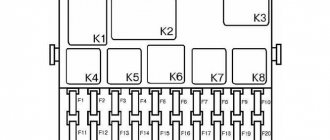
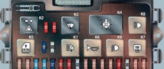
VAZ 2112 fuse diagram
With an 8-valve and 16-valve engine, it is equipped with a main mounting block, and since 2008 an additional console has been added. A diagram with element markings is printed on the left side of the main block cover and placed below.
The designations of all elements are presented below. You can find the transcript in the table.
| Circuit breakers | Power, A | What protects |
| F1 | 5 | Lamps for turning on the license plate lighting, instruments, side lights, trunk, left side. |
| F2 | 7,5 | Low beam |
| F3 | 10 | Further |
| F4 | 10 | PTF |
| F5 | 30 | Door windows |
| F6 | 15 | Portable lamp (socket) |
| F7 | 20 | Engine cooling fan. Sound signal. |
| F8 | 20 | Rear window heating element. Relay for turning on the heated rear window. |
| F9 | 20 | Recirculation valve. Cleaners, windshield and headlight washers (wiper fuse). Relay for turning on the heated rear window. |
| F10 | 20 | Spare |
| F11 | 5 | Starboard side marker lamps |
| F12 | 7,5 | Middle left |
| F13 | 10 | Far left. Power indicator lamp |
| F14 | 10 | Left PTF |
| F15 | 20 | Electrically heated seats. Trunk lock lock |
| F16 | 10 | Turn signals and emergency lights. |
| F17 | 7,5 | Interior lighting. Ignition switch. Stop signal. Watch. |
| F18 | 25 | Glove compartment lighting. Heater controller. Cigarette lighter fuse. |
| F19 | 10 | Locking door locks. Relay for monitoring the serviceability of brake light lamps and dimensions. Direction indicators. Reversing light. Generator excitation winding. On-board control system display unit. Instrument cluster. Watch. |
| F20 | 7,5 | Rear fog lamps. |
Relay
- K1 - lamp health monitoring;
- K2 - windshield wiper;
- KZ - direction indicators and emergency lights;
- K4 - switch on low beam;
- K5 - high beam;
- K6 - additional relay;
- K7 — heated rear window;
- K8 - rear PTF.
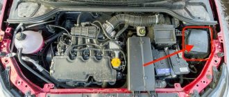
Starter fuse and relay
Installed on the device itself between the engine and the fan radiator. If signs of a malfunction appear, it is better not to delay replacing the element and install a new relay.
Fuel pump fuse and relay
Located in the additional interior installer - No. 3. Responsible for the fuel pump relay No. 5.
Relay and fuse for cigarette lighter
No. F18 is rated at 25 Amps.
Stove
The 25 A element F18 is responsible for protecting the operation of the electrical circuit of the heater motor.
Turn signals
The elements are marked as F19 and are rated at 10 Amps.
Brake lights
Located in the main block - No. F17. Its power is 7.5 A.
Where is the alarm fuse located?
No. F16 and rated 10 A.
Cooling Fan
The F7 element with a power of 20 Amperes is responsible for its protection.
Which fuse goes to the radio?
This is an F4 rated at 20 A.
Window lifters
F5 at 30 A.
Fuse and relay for central locking VAZ 2112: where is it located
They can be found in a separate box behind the main mounting block.
Ignition
The main relay is located in the additional cabin unit, where it is number 6.
Reverse
F19 with a rating of 10 Amperes is responsible for the lamps.
Fogs
Protected by three inserts: right - F4, left - F14, and rear - F20. The power of all PTFs is 10 Amps. In case of tuning, you may need to replace them with new ones along with the fog lights. The connection occurs via switch K8.
Lamp health monitoring relay
Marked as K1 in the main block of the VAZ 2112.
Brake
Installed under the brake pedal.
Relay and fuse for injectors
The additional element F3 is rated at 15 Amps.
Fuse for interior light
The F17 element with a power of 7.5 A is responsible for the safe operation of the VAZ 2112 interior lighting lamp.
Number plate illumination
Corresponds to F1 with a rating of 5 Amps.
Generator
A three-level relay voltage regulator is located on the device. It is better to replace the factory element with a new one, since three-level voltage regulation often leads to a short circuit.
Heated rear window
Relay K7 is responsible for turning on. Protects the F8 electrical circuit with a rating of 20 Amps.
Seat heating
It is protected by a 20 Amp F15 insert.
Wiper relay
This is a K2 and without its stable operation there will be no washer supply to the windshield, and the wipers will not be able to do their job.
Charger
They placed it next to the device - one of the few elements of this kind under the hood of a car.
Low and high beam VAZ 2112
It is protected by fuses F2 and F12 (left and right headlights), and the high beam is protected by F3 and F13 (left and right). The first has a rating of 7.5 A, and the second has a rating of 10 A.
Fuse for the dashboard of VAZ 2112
Located in the wiring harness leading to the instrument panel from the battery.
Dimensions
There are 2 fusible elements - F1 and F11, left and right. The power of both is 5 Amperes. Factory fuses require replacement due to the fact that the dimensions often burn out due to their malfunctions.
Heated seats
It is protected by an element marked F15 for 20 Amperes.
VAZ 2112 speedometer fuse: where is it located?
He's gone.
Opening the trunk
This is an F1 and is rated at 5A.
Fuse F6
Responsible for protection against burnout of the car socket. Its rating is 15 Amperes.
VAZ 2112: fuse F17 blows
Most often, this element, which is responsible for interior lighting, fails due to a battery failure. Its power is 7.5 A.
Fuse F19
Responsible for protecting the brake light, reversing lights and dimensions.
Relay K1
An element of lamp serviceability, which in older versions is replaced by a jumper.
Relay K6
This is a reserve item.
Speed sensor
Located on the wiring harness leading to the device.
Additional mounting block Priora
- F1 (15 A) – main relay and starter interlock circuit fuse;
- F2 (7.5 A) – fuse for the power supply circuit of the ECU (controller);
- F3 (15 A) – Priora fuel pump fuse;
- K1 – main relay;
- K2 is the place where the Priora fuel pump relay is located.
Attention!
The relay and fuse diagram may differ depending on the configuration and production date of the vehicle. Current diagrams of the mounting block are presented in the operating manual for the date of manufacture of the vehicle ().
Let us remind you that on our website you can find detailed instructions for repairing the Lada Priora with your own hands.
Keywords: Lada Priora mounting block | Lada Priora torpedo
9 6 1 3 2 1
Share on social networks:
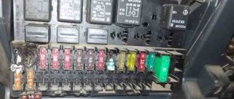
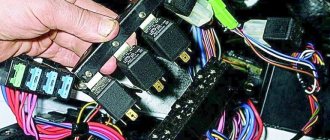
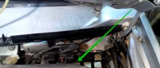
Starter, ignition, rear fog lamp relay
In order to carry out quick checks and repairs, the ignition system relay is installed under the front dashboard of the car, behind the hood release handle. It is located just below the central dashboard. The module is closed with a plastic plug, which must be opened slightly to test for functionality.
Starter, ignition, rear fog lamp relay
Next to the indicated relay, there is a similar one for the rear fog lights and the starter.
The main task of the relay when igniting is to reduce the applied load to the contacts. When the engine starts, the relay turns off some electrical circuits in the vehicle system. The system is used not only in injection, but also in carburetor engines.
In the event of a malfunction or malfunction in the ignition system, it is necessary to monitor the operation of the relay. For this purpose, open the box and carefully remove the desired element. It is attached using contacts to special grooves. The first thing to do is look at the oxidation of the contacts, if necessary, clean them with a soft cloth or treat them with a special liquid.
To check functionality, you need to use a regular multimeter. We connect to incoming connections and check the numbers. If there is no short circuit when current is applied, it means the element is not working. Replacement is carried out in a similar manner. It is necessary to use a standard element with the number of amperes indicated on the housing.
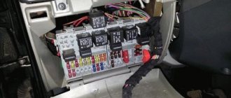
Location
The relay and fuse mounting block is located on the left side of the steering column in the instrument panel.
Types of mounting blocks
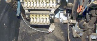
Block 2110-3722010
Block 2110-3722010-01
Block 2110-3722010-08
Cigarette lighter diagnostics and repair
If after replacing the protective element the element does not start working, then the reason must be looked for elsewhere. It is not always necessary to install a new device; you can repair the cigarette lighter. First of all, you need to check the wiring that goes from the network to the socket. You should test the wires with a multitester. If there is no power during diagnostics, this indicates a broken wire. Repairs will require new parts, rosin, tin and a soldering iron.
The second malfunction, which does not require a complete replacement of the cigarette lighter, is the breakdown of the mica fuse, which is located inside the device. To do this, you need to disassemble the socket of the socket and find a small mica semiconductor (it may melt). It is dismantled, replaced with a new one, after which everything is put back together and the functionality of the device is checked.
How to remove the cigarette lighter of a VAZ-2110
To remove the cigarette lighter on a VAZ, you need:
- Open the hood. Then remove the negative cable from the battery and take out fuse F18.
- Unscrew the fasteners and remove the 2 parts of the cladding.
- Pull out the three-pin plug.
- Remove the trim under the handbrake and the cover from the gearbox.
- Move the seats back, unscrew the tunnel fasteners and pull out the cartridge.
- Pry the cigarette lighter latch and remove the socket for repair.
Connecting a new
The cigarette lighter is connected in the reverse way:
- A working device is installed.
- The facing casing of the gearshift lever and handbrake is mounted in place.
- A three-pin plug is connected.
- Then you need to connect to power.
- Check the correct connection and functionality of the cigarette lighter.
Pinout
The layout of the elements is as follows:
- The red wire is responsible for the plus and is connected to the device through fuse No. 18. It is capable of passing a current of no more than 25 A. Exceeding it leads to burnout of the wire.
- The yellow cable in the pinout is also a plus and will be used to highlight the part.
- The black wire responsible for power is negative. One end goes to the device, and the other to the battery.