Vesta » Maintenance and repair
Knowledge of the features of the LADA Vesta fuse circuit (2180, 2181) will help the owner of this car eliminate the problem that has arisen with the operation of electrical equipment.
Below is a diagram and pinout of fuses and relays for LADA Vesta 2015, 2016, 2022, 2022, 2022, 2022, 2022 model years. Depending on the configuration (Luxe, Classic, Comfort, Exclusive), there is variability in decoding.
Power unit in the engine compartment
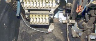
The mounting block itself is located near the battery (shown in the photo below). All electrical circuits in it are reliably protected from moisture and dust using a sealed cover equipped with special latches. This adds a little comfort when operating the car.
To open the specified cover, you need to press the two latches along the edges, which are shown by arrows in the photo below.
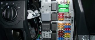
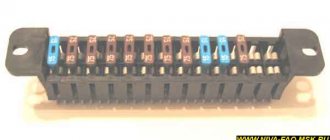
After the block is opened, many fuses and executive relays are revealed. To avoid confusion, we numbered them all in the photo below and added a description to each element in Table 1.
The circuits that the fuses protect are shown in Table 1.
Table 1. Circuits protected by fuses in the engine compartment block
In some car modifications, the horn is protected by fuse F78 instead of F73. And food is extra. equipment in the trunk is protected by fuse F55.
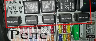
The relays that are located in this block are also summarized in Table 2:
Table 2. Relays located in the engine compartment block.
How to check the fuse?
At home, it is better to use a multimeter. When connecting the terminals to the module, the scale of the device should not gravitate towards infinity, since this is an open circuit.
In workshops and service stations, special portable scanners are used for diagnostics to read data from the electronic engine control unit via a diagnostic connector.
Related link:
Comparison of Lada Vesta and KIA Rio. Can a Russian-made car be a worthy competitor to popular foreign cars?
Block in the car interior
The passenger compartment fuse box is located below the left of the steering column.
Opening the lid on the old version before modification
To gain access to it, you need to remove the special clamps (before modification) that hold the cover diagonally from the bottom, and then pull it from the bottom. Don't forget about the upholstery holder lock. It must be carefully disconnected. In addition, in order for the cover to be removed completely, you will need to disconnect two connectors from the luggage compartment button and the electric headlight adjustment.
There is also a modified version of the cover. How to remove it - watch the video:
After removing the cover, you will see a mounting block with all low-current fuses and relays.
The main fuses are located in 2 rows. The counting goes from below from F1-F20 and from F21-F40 in the second row, respectively.
Slightly higher are the more powerful (20A-30A) F41-F46. The relays run along the left side of the block, also starting from the bottom.
Rice. 2. Schematic location of relays and fuses
In new modifications, the fuse box has been supplemented with:
Here is a list of all circuits with the numbers of the fuses by which they are protected. To check whether the fuse is working, it is enough to shine it into the light and a break in the fusible metal inside will be visible if it is faulty.
Attention! Before installing a new replacement fuse, make sure that the circuit being protected is actually working and there is no short circuit. After all, fuses don't just blow! This means there was some kind of overload, from which the fusible element saved the wiring and the car from fire.
Table 3. Description of fuses in the interior block (until 2022).
| Fuse no. | Rated current | Protected vehicle circuit |
| F1 | 15A | Right steering column switch power supply, windshield washer |
| F2 | 30A/5A | Left steering column switch |
| F3 | 10A | Left high beam headlight, non-luxury equipment |
| F4 | 30A/5A | Left steering column switch |
| F5 | 15A | Seat heating |
| F6 | 7.5A | Right side lights |
| F7 | 10A | Left side lights |
| F8 | 5A | Rear fog lights |
| F9 | BEHIND | Right turn signal in the mirror |
| F10 | 5A | AMT robotic gearbox selector |
| F11 | 10A | Left low beam headlight (not luxury) |
| F12 | 15A | BCM Controller (Turn Signals) |
| F13 | 10A | BCM controller (self-powered) |
| F14 | 10A | Turning off the brake pedal |
| F15 | 5A | Power supply for rain and light sensor, headlight range control |
| F16 | 5A | Turning off the brake pedal |
| F17 | 5A | Lighting for trunk, glove compartment, sills |
| F18 | 3A | Left turn signal in the mirror |
| F19 | 10A | Right low beam headlight (not luxury) |
| F20 | 5A | Heated exterior mirrors |
| F21 | 15A | BU SNPB |
| F22 | 5A | Instrument cluster |
| F23 | 5A | Instrument cluster |
| F24 | 5A | ERA GLONASS, radio |
| F25 | 5A | ESP9.1 controller |
| F26 | 15A | Power supply to fuel pump module |
| F27 | 5A | Power supply for parking sensors |
| F28 | 5A | EURU controller (electric power steering) |
| F29 | 10A | Power supply for trailer lighting |
| F30 | 5A | ERA GLONASS controller |
| F31 | 5A | ERA GLONASS controller |
| F32 | 10A | K15M Bus Power (Engine Compartment) |
| F33 | 5A | Window control |
| F34 | 5A | Power supply for steering angle sensor, steering wheel button block |
| F35 | 5A | Driver's door switch block |
| F36 | 15A | Radio, diagnostic connector |
| F37 | 7.5A | Stop lamps, right |
| F38 | 7.5A | Stop lamps left |
| F39 | 10A | DRL (not luxury) |
| F40 | 10A | Right high beam headlight not luxury equipment |
| F41 | 20A | 12V socket (power supply for additional devices), cigarette lighter fuse for Lada Vesta |
| F42 | 20A | BCM controller (VTR bus power supply) |
| F43 | 20A | BCM Controller (Door Locks) |
| F44 | 30A | Window lifters |
| F45 | 30A | Interior heater fan |
| F46 | 30A | Wiper (switch power) |
| F47 | 25A | EMM controller (PDS, lBS, lGO) |
| F48 | 30A | EMM controller (windshield wiper) |
| F49 | 25A | EMM controller (PTF, ZPTO, license plate lighting) |
| F50 | 25A | EMM controller (lDS, PBS, PGO) |
Fuse table as of February 2022:
All that remains is to figure out the relays used and the circuits that they switch in the block. The description is given in the table below.
Table 4. Description of the relays located in the interior unit.
| Relay | Relay rating | Switched circuit |
| K1 | 70/50A | Power supply for lighting and seat heating |
| K2 | 30A | Reserve |
| K3 | 30A | Heated rear window |
| K4 | 30A | Front windows |
| K5 | 40A | Interior heater fan |
| K6 | 30A | Rear window lifter |
| K7 | 20A | Fuel pump module |
| K8 | 20A | ACC accessories (+12V socket power supply) |
Review of Manufacturer Prices
| Name/article | Price in rubles |
| Housing cover Lada Vesta 8450007436 | From 300 |
| Jcase | From 180 / piece |
| Mini | From 140 / piece |
| EMM-T4 231A03142 (Renault) | From 170 / piece |
| PF895652A2 (Japan) | From 220 / piece |
*price indicated as of March 28, 2019.
Conclusion
Installing new power modules requires careful attention on the part of the technician. It is unacceptable to violate the current range. The exact data for each of the fuses is indicated in the operating instructions for the technical device. If difficulties arise, contact service station specialists for help.
Graphic cheat sheet
To make it easier for you to find a faulty fuse, we have prepared a graphical hint for you with markings and numbering of elements.
Fuses linked to external and internal equipment for 2022.
Fuses linked to external and internal equipment from 2022 onwards.
If you still have questions on the topic, we will be glad to see them in the comments to this post.
Reviews
| № | Positive |
| 1. | Georgy Nikolaevich , 42 years old (drive2.ru): the car has been three years old since purchase, I haven’t made any investments, only scheduled maintenance. The fuses are all standard, nothing has been changed. |
| 2. | Mikhail , 48 years old (prom.ua): in two years I replaced two power modules once. I didn’t contact the service, I limited myself to my experience and skills. |
| 3. | Sasha , 38 years old (autotoday.com): There are no complaints about the standard power modules yet, the car is only a year old, but I heard that you can install a unit from Renault Duster, Logan of the second generation. |
| 4. | Kirill , 45 years old (rozetka.ua): mileage 75,000 km, only recently replaced five power modules with new ones. I believe that a resource of 75,000 km is more than enough for domestic transport. Of course, there is still a long way to go to reach foreign brands, but this is progress. |
| 5. | Petrovich , 44 years old, (avtoflit.com): I bought the car second-hand, good condition, five years old. I didn’t do anything to the power system, the units are operating normally. |
| 6. | Nikolaevich , 45 years old, (autotoday.com): I am satisfied with the quality of manufacturing and assembly of the Lada Vesta, no comments. I fix minor damage myself. |
| 7. | Vasilievich , 41 years old, (drive2.ru): the car is four years old, only recently replaced three relays - breakers in the engine compartment. Good build quality Lada. |
| Negative | |
| 8. | Nikiforovich , 49 years old (prom.ua): problems with the power system began after buying the car. I repeatedly contacted the service station due to burnt-out power modules. The problem is still not resolved. |
| 9. | Nikolai Semenovich , 46 years old, (avtoflit.com): I do not recommend standard fuse blocks for the Lada Vesta. If possible, replace with new ones from Renault Duster, Logan of the second generation. |
| 10. | Vyacheslav Petrovich , 47 years old, (drive2.ru): the car is new, but the weak points are inherited from previous generations. |
| 11. | Stanislav Vasilyevich , 39 years old, (autotoday.com): after two years of operation, the car began to crumble in the literal sense of the word. The build quality is still raw and needs improvement. |
Related link:
Blizzak winter tires.
Replacing the fuse box for the Lada Vesta St. Cross
Necessary tools, materials:
- rags;
- additional lighting as needed;
- a set of new relays;
- plastic clips in the amount of 3 - 5 pieces, in case the standard ones are damaged.
Sequence of actions when replacing the power supply in the engine compartment:
- The car is installed within the perimeter of the repair area, the hood is open, and the parking brake is depressed.
- Behind the battery, closer to the air filter housing, a module with fuses is installed. We unclip the side latches and remove the relay with the serial number we need.
- We troubleshoot the power supply, clean the internal contents from dust and dirt.
- We install a new “relay” and assemble the structure in the reverse order.
Algorithm of actions when replacing inside the car:
- We turn off the engine and lock the parking brake.
- In the lower left part of the dashboard, behind the steering rack, we find the power supply cover, snap off the four plastic clips.
- We remove the cover, unscrew the three latches, and lift the power supply towards you.
- We inspect the module, replace non-working “relays” with new ones, and assemble the structure in the reverse order.
Schematic layout
In the interior mounting block you will see the following picture:
Interior mounting block
On a note!
In the lower right corner there are spare fuses for the Lada Vesta.
Schematically the block looks like this:
Schematic location of fuses Explanation of spare fuses Explanation of spare fuses Explanation of spare fuses
Relays that are present in the cabin:
Symbols for the snout in the cabin Body connector Layout of buttons on the steering wheel
Scheme
Fuse designation
| 60 | 40A Control unit for anti-lock brakes and directional stability systems (ABS/ESP) |
| 61 | 70A Electric power steering (EPS) |
| 62 | 60A '15-'17: Generator |
| 70A '18-'21: Robotic transmission control unit | |
| 63 | 60A '15-'17: Generator |
| 64 | 60A '15-'17: Terminal K30S |
| 65 | 60A '15-'17: Heated windshield |
| 66 | 70A '15-'17: Robotic transmission control unit |
| 67 | 40A Engine Cooling Fan Relay |
| 68 | 60A '18-'21: Terminal K30S |
| 69 | 30A '15-'17: Heated rear window |
| 60A '18-'21: Heated windshield | |
| 71 | Reserve |
| 72 | 15A Control unit for engine control system for CNG compressed natural gas (methane) |
| 70A '18-'21: Generator | |
| 73 | 5A Engine control system control unit for CNG compressed natural gas (methane) |
| 70A '18-'21: Generator | |
| 74 | 10A '15-'17: Anti-theft system horn relay (siren) |
| 15A '18-'21: Air conditioning compressor clutch | |
| 75 | 5A Robotic gearbox control unit |
| 76 | Reserve |
| 77 | 15A '15-'17: Air conditioning compressor clutch relay |
| 30A '18-'21: Heated rear window | |
| 78 | 15A Air conditioning compressor clutch, radiator fan control unit relay |
| 79 | Reserve |
| 80 | 10A '15-'17: Oxygen sensor, canister purge valve, timing valve |
| 7.5A '18-'21: Oxygen sensors (DK1, DK2), canister purge valve (KPA), intake module damper valve (IDM), gas distribution valve (GRM) | |
| 81 | 5A Reversing light switch |
| 82 | Reserve |
| 83 | Reserve |
| 84 | 25A Control unit for anti-lock brakes and directional stability systems (ABS/ESP) |
| 85 | 10A Horn, anti-theft horn ('18-'20) |
| 86 | 5A Heated windshield relay coil |
| 87 | Reserve |
Relay decoding
| R1 | Heated windshield No. 2 | |
| R2 | '15-'17: Heated windshield #1 | |
| '18-'21: Engine cooling fan | ||
| R3 | '18-'21: Heated windshield No. 1 | |
| R4 | Starter | |
| R5 | Engine control unit (ECU) | |
| R6 | A/C compressor clutch | |
| R7 | '15-'17: Engine Cooling Fan | |
| '18-'21: Starter | ||
| R8 | Sound signal | |
| R9 | Anti-theft alarm sound | |
LADA VESTA. DIAGNOSTIC CARDS OF THE M86 ENGINE CONTROLLER 21129 EURO-5
Map A-4
Checking the main relay and power circuit
Circuit Description
When the ignition is turned on, voltage from the ignition switch is supplied to contact “X1.1/A5” of the controller. The controller, through contact “X1.1/J3”, turns on the main relay, through which the supply voltage is supplied to contacts “X1.1/L3” and “X1.1/K3” of the controller, as well as to sensors and some controlled devices (canister purge valve , injectors, relays).
Description of checks
1 Voltage is supplied to contact “X1.1/A5” of the controller from the ignition switch.
2 The diagnostic device shows the voltage of the on-board network, determined by the controller from the voltage at contacts “X1.1/L3” and “X1.1/K3”. It should not differ by more than 1 V from the battery voltage.
3 There should be battery voltage present at the contacts of the harness block to terminals “85” and “30” of the relay. If power is present on both contacts, the light of the probe connected to ground should light up when you touch them.
4 The previous test determined the presence of voltage at the contact of the harness block to terminal “85” of the relay. This test monitors the main relay control circuit, which must be closed to ground by the controller.
5 The serviceability of the main relay is checked.
The reason for the incorrect value of the on-board voltage, determined by the controller from the voltage at contacts “X1.1/L3” and “X1.1/K3”, may be a short to ground in the power supply circuits to the relays and actuators, as well as incorrectly connected anti-theft devices.
Map A-5
Checking the electrical circuit of the fuel supply system.
Circuit Description
When the ignition is turned on, the controller turns on the electric fuel pump relay and the electric fuel pump starts working. If there are no reference pulses from the crankshaft position sensor (the engine is not running), the controller turns off the electric fuel pump through
2 s after turning on the ignition.
Description of checks
The sequence corresponds to the numbers on the card.
1 The electric fuel pump is forced on.
2 Check the presence of +12 V voltage at the contacts of the electric fuel pump relay.
3 When the ignition is turned on and the engine is cranked, the controller should turn on the electric fuel pump.
Injector ramp assembly for engine 21129:
1 — injector ramp; 2 — fitting for monitoring fuel pressure; 3 - nozzle; 4 - sealing ring; 5 — nozzle clip
Video on the topic “Checking the main relay and power circuit of the Lada Vesta”
ECU repair. No spark. VAZ car won't start. The fuse is on.
https://youtube.com/watch?v=eSW_JQyzuuc
Lada Granta - Mounting block (fuses and relays)
Lada Granta problems with relay
Causes and solutions
The first problem and the second problem can only be encountered by a beginner who has this first car and has not yet read the instructions for it. The fact is that the standard connection of the stereo system implies its operation only when the ignition is turned on. That is, I got into the car, started the engine (or simply turned the key in the lock), and turned on the music. This is done to save battery charge. But if you are not satisfied with this situation, then contact electricians who will quickly make the device “independent”.
The next problem is a barely noticeable indication on the display. This happens exclusively in cold weather, at sub-zero temperatures. The problem is easily solved by warming up the interior and within 15 minutes everything returns to normal. It’s hard to call this a malfunction; most likely, this is a feature of the displays.
It happens that when you briefly press the power button, the device does not respond. In such a situation, the advice is simple - hold the key for a few seconds. Perhaps these are isolated cases associated with a specific device, but this still happens sometimes.
In some situations, the car radio may have a software failure and not respond to attempts to turn it on. To do this, a reset is provided on the front panel. Next to the power button there is a hole in which the reset key is located. To activate it, you need to gently press it with something sharp and hold it for a few seconds. Sometimes this helps to “reanimate” the radio.