Share:
This article shows the fuse box of cars of various brands. The fuse box diagram is presented for various cars. The location of the fuse box is shown. The decoding of the fuse box is presented in tabular form. The pinout of the fuse box of some machines is described in detail. The fuse box of several VAZ models is described.
Name of the fuse and relay box for the following vehicles:
- Fuse box UAZ Simbir 3162, 31602 Fuse box decoding
- Fuse box diagram for UAZ Simbir 3162, 31602
- Electrical protection unit for the all-terrain vehicle UAZ Patriot 316300 since 2005
- Package of electrical fuses for cars UAZ-374195, UAZ-396295, UAZ-396255, UAZ-390995, UAZ-220695 Loaf and UAZ-330395, UAZ-330365, UAZ-390945 Tadpole 2011
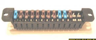
Fuse box UAZ Simbir 3162, 31602
Designation in the fuse box picture:
- K2 - windshield wiper relay;
- K3 — direction indicator stick;
- K4 — electric relay for low-beam headlights;
- K5 — switch for turning on high-beam headlamps;
- K6 - additional (unloading) switch;
- K7 - solenoid for turning on the rear window heating;
- K8 - electromagnet for turning on fog lamps;
- F1-F23 - fuses (see table)
Fuse block diagram:
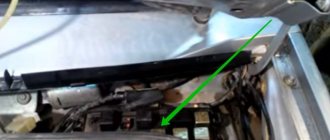
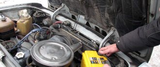
The power unit is installed in the car interior, on the left, under the instrument panel, opposite the driver’s seat.
Healthy ! Crankshaft sensor
Decoding the fuse box UAZ Simbir 31602:
| Designation | Current strength, A | Protected Circuits |
| Assembly electrical module | ||
| F1 | 5 | Instrument lighting, left side side lights |
| F2 | 7,5 | Low beam of the right electric headlight |
| F3 | 10 | Far illumination of the right lamp |
| F4 | 10 | Right fog light |
| F5 | 30 | Glass door lift system, electric sunroof drive |
| F6 | 15 | Portable lamp socket |
| F7 | 20 | Horn, electric mirrors |
| F8 | 20 | Rear window heating element |
| F9 | 20 | Glass cleaners and washers |
| F10 | 20 | Reel for headlamp cleaners |
| F11 | 5 | Side lights, right side, license plate light |
| F12 | 7,5 | Near left headlamp |
| F13 | 10 | Left high-beam light and high-beam indicator |
| F14 | 10 | Left fog light |
| F15 | 20 | Door lock system |
| F16 | 10 | Hazard warning and direction indicators |
| F17 | 7,5 | Courtesy lights, engine compartment lamp, brake light switch |
| F18 | 25 | Heater, cigarette lighter, rear window defroster switch |
| F19 | 10 | Instrument cluster, reverse light switch, on-board control system |
| F20 | 7,5 | Rear fog |
| F21 | 10 | Backup electrical fuse |
| F22 | 20 | Spare electrical plug |
| F23 | 30 | Emergency traffic jam |
The main relay 90.3747-10 (RF) is located on the front panel, above the engine, next to the fuel pump relay.
The fuel pump solenoid type 90.3747-10 (RF) is installed on the bulkhead, above the engine, next to the main electromagnet KMPSUD and the intermediate starter switch (retractor solenoid).
The intermediate starter relay is installed on the front panel, above the engine, next to the main relay KMPSUD and the fuel pump relay.
The main solenoid circuit coming from the battery is protected from short circuits to ground by a 20 A harness fuse type 688670-7 (AMP) or 354.3722 (RF). At the same time, the KMPSUD ignition circuit is protected from short circuits to ground by a 10 A harness fusible plug of type 688670-5 (AMP) or 352.3722 (RF). The plugs are placed in blocks that are attached:
- 20A - to the main relay;
- 10A - to the electric fuel pump relay.
Healthy ! Camshaft sensor
Relay functionality
A relay is an electrical unit that helps regulate electrical networks with the required network parameters. The types of relays are adjusted depending on the type of incoming signal. The relay helps distribute high load currents. That is, it switches electrical flows in connection with the specified parameters. The relay operates when the mechanism (horn, heated mirrors, air conditioning) uses a higher current (up to 40 A).
For example, to start the engine by turning the keys, the starter must be turned on. Consuming high current (up to 300 A). If you do not use a relay, the ignition switch contacts and wiring will burn out. Unable to withstand the load of such force. For this purpose, a connection is made via a relay (a relay is installed between the ignition switch and the starter). Which, when a low current is supplied, closes the necessary network. This way the starter starts without damaging the weak links in the chain.
Fuse box UAZ Patriot
Fuse box UAZ Patriot 316300 from 2005
- K2 — windshield wiper relay;
- K3 - turn signal interrupter relay;
- K4 - relay for low beam headlights;
- K5 - headlight high beam relay;
- K6 - additional (unloading) relay;
- K7 — relay for turning on the heated rear window;
- K8 - relay for turning on fog lights;
- F1-F23 - fuses (see table)
- K1 - starter relay;
- K2 — rear door windshield washer time relay;
- K3 - relay for the electric fan of the engine cooling system;
- K4 - sound signal relay;
- K5 - electric fuel pump relay;
- K6 - relay KMPSUD;
- F1-F5 - fuses (see table).
Decoding of the fuse box of UAZ Patriot 316300 from 2005:
Healthy ! temperature sensor
| Designation | Current strength, A | Protected Circuits |
| Mounting block | ||
| F1 | 5 | Instrument lighting, left side side lights |
| F2 | 7,5 | Low beam right headlight |
| F3 | 10 | High beam right headlight |
| F4 | 10 | Right fog lamp |
| F5 | 30 | Electric door window system, electric sunroof |
| F6 | 15 | Portable lamp socket |
| F7 | 20 | Horn, electric mirrors |
| F8 | 20 | Rear window heating element |
| F9 | 20 | Glass cleaners and washers |
| F10 | 20 | Reserve |
| F11 | 5 | Side lights, right side, license plate light |
| F12 | 7,5 | Low beam left headlight |
| F13 | 10 | Left high beam and high beam warning light |
| F14 | 10 | Left fog lamp |
| F15 | 20 | Electric door lock system |
| F16 | 10 | Hazard warning and direction indicators |
| F17 | 7,5 | Courtesy lights, engine compartment lamp, brake light switch |
| F18 | 25 | Heater, cigarette lighter, heated rear window switch |
| F19 | 10 | Instrument cluster, reverse light switch |
| F20 | 7,5 | Rear fog lights |
| F21 | 10 | Spare fuse |
| F22 | 20 | Spare fuse |
| F23 | 30 | Spare fuse |
| Relay and fuse box | ||
| F1 | 10 | Electric fuel pump relay power circuit |
| F2 | 20 | KMPSUD relay power circuit |
| F3 | 20 | Starter relay power circuit |
| F4 | 25 | Fan relay power circuit |
| F5 | 80 (90) | Mounting block power supply |
Fuse box UAZ Patriot 316300 from 2007
Fuse block diagram:
- K2 — windshield wiper relay;
- K3 - turn signal interrupter relay;
- K4 - relay for low beam headlights;
- K5 - headlight high beam relay;
- K6 - additional (unloading) relay;
- K7 — relay for turning on the heated rear window;
- K8 - relay for turning on fog lights;
- F1-F23 - fuses (see table)
- K1 - starter relay;
- K2 — rear door windshield washer time relay;
- K3 - sound signal relay;
- K4 - relay KMPSUD;
- K5 - electric fuel pump relay;
- K6 - electric fan relay;
- K7 - electric fan relay;
- F1-F10 - fuses (see table)
- K1 - relay for turning on the interior heater fan;
- K2 - recirculation damper relay 1;
- K3 - recirculation damper relay 2;
- K4 - compressor clutch relay;
- K5 - fan relay 1;
- K6 - fan relay 2;
- F1-F3 - fuses (see table)
Healthy ! Throttle sensor
Explanation of the fuse box:
| Designation | Current strength, A | Protected Circuits |
| Mounting block | ||
| F1 | 5 | Lighting of switches and controls, side lights of the left side |
| F2 | 7,5 | Low beam right headlight |
| F3 | 10 | High beam right headlight |
| F4 | 10 | Right fog lamp |
| F5 | 30 | Electric door window system, electric sunroof |
| F6 | 15 | Portable lamp socket |
| F7 | 20 | Sound signals, electric mirrors |
| F8 | Heated rear window, exterior mirrors MUS | |
| F9 | 20 | Window cleaners and washers, additional interior heater |
| F10 | 20 | Cigarette lighter |
| F11 | 5 | Side lights, right side, license plate light |
| F12 | 7,5 | Low beam left headlight |
| F13 | 10 | Left high beam and high beam warning light |
| F14 | 10 | Left fog lamp |
| F15 | 20 | Electric door lock system |
| F16 | 10 | Hazard warning and direction indicators |
| F17 | 7,5 | Courtesy lights, brake light switch |
| F18 | 25 | Heater, switch for heated rear window and exterior mirrors |
| F19 | 10 | Instrument cluster, reverse light switch |
| F20 | 7,5 | Rear fog lights |
| F21-23 | 10; 20; 30 | Spare fuses |
| Relay and fuse box | ||
| F1 | 30 | Fan relay power circuit |
| F2 | 25 | Anti-lock braking system (ABS) |
| F3 | 5 | Devices |
| F4 | 10 | Electric fuel pump relay power circuit |
| F5 | 20 | Starter relay power circuit |
| F6 | 30 | Fan relay power circuit |
| F7 | 20 | Power circuit of relay KMPSUD |
| F8 | 10 | Anti-lock braking system (ABS) |
| F9 | 80 (90) | Mounting block power supply |
| F10 | 40 | Anti-lock braking system (ABS) |
| Relays and fuses | ||
| F1 | 7,5 | A/C compressor clutch |
| F2, F3 | 30 | Fan 1, Fan 2 |
Common questions that most often arise among Lada Priora users
Safety section for the cigarette lighter of Lada Priora
In the Lada Priora, fuse F13 is responsible for the correct functioning of the cigarette lighter.
Safety section for windshield wipers Lada Priora
Fuse F11 (installation compartment) is responsible for the functionality of the wipers. And relay K6 regulates the functions of the washer and glass wipers.
Safety section for low beam headlights
In this option, you should look at fuse F6 and F7 (mounting compartment). They go to the headlights on both sides.
Safety section for the stove
The heater is supplied with fuse F9 (also the heater fan).
Safety section for power lifts
The glass lifting movement is controlled by fuse F31. It is secured in the mounting compartment.
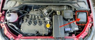
Priora under the hood photo
Mounting fuse block UAZ Patriot 2022
| On this model of the UAZ Patriot 2118 SUV there are two mounting blocks of fuses and relays. Their installation locations are presented here. Images and diagrams of the location of fuses and relays are posted. The explanations of all blade fuses and relays that are equipped with the mounting blocks are summarized in tables. They describe which electrical circuits a particular fuse protects and which device protects this or that relay. |
Operating principle of the fuse
Electronics are an important component of all modern cars. Like all automatic systems, electronics are subject to overheating, overvoltage and surge current. To protect the car's electrical appliances from unwanted influences, manufacturers install fuses on cars. The main purpose of this functionality is to protect the electrical network. When manufacturing Lada Priora cars, fuses with inserts that can melt in an emergency are installed.
When the electrical network is overloaded, such an element overheats, melts and breaks the network. To produce fusible links, one or several types of metal are created. The basis for fusible elements is made from glass filling. The fuse consists of fasteners, between which there is a fusible part. This fuse system is distinctive for Lada Priora cars. In Priora, the location of fuses is oriented towards the safe operation of the vehicle.
VAZ 2114 fuse box
| A view of the fuse box and its diagram are located here. The installation location of the VAZ 2114 fuse box is indicated. Its electrical circuit is located. The designation of each fuse and relay, as well as which electrical circuit they protect, is summarized in the table. Here the pinout of this block is laid out and each contact of the connecting sockets (Plugs) is described in detail. At the end there are detailed instructions for replacing the VAZ 2114 fuse mounting block. |
Electromagnetic relay
The electromagnetic relay closes the moving contacts. And fixed contacts when a low current is applied to it. Inside the relay there is a switch and an electromagnet. Representing the winding and core. When current enters the relay block, an electromagnetic field appears, pulling the armature with movable contacts towards itself. In this case, the contacts are connected and the current is redirected through them.
After the end of the low current, the spring returns the armature to its initial position. Thereby opening the contacts. The electrical circuits of the electromagnet and contacts are reliably isolated, that is, they are not interconnected. For more accurate operation of the relay and elimination of unwanted interference, additional electronic elements can be built into it. Like resistor, capacitor, diode, etc.
Relays are widely used in the automotive industry. And it is installed in the Lada Priora model according to the manufacturer’s diagrams.
VAZ 2107 fuse box
| Here is a complete description of the electrical wiring and the mounting block of fuses and relays of the VAZ 2107. The location is indicated. Images of the old and new mounting blocks have been posted. There is a pinout diagram of the connecting sockets and an electrical diagram of the connections inside the mounting block. A description of each fuse is provided. Information about the protected circuits by each fuse and relay is tabulated. The sequence of replacing the fuse box of a VAZ 2107 passenger car is described. |
Additional block
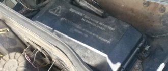
Location of the additional block with fuses and relays.
There is an additional block in the central panel, the location of which can be seen in the photo. It contains three fuses with the same power of 15A:
- The first is responsible for the controller and ignition module in the VAZ 2110.
- The second takes over the protection of the mass flow sensor (mass flow meter), purge valve, heating and speed sensor.
- The third is responsible for the injectors and fuel pump.
And three relays:
- The fourth number indicates an electric fan.
- Under the fifth is an electric fuel pump.
- The last relay relates to the ignition of the VAZ 2110.
Mounting block of fuses and relays VAZ 2109
| This page presents two types of fuse and relay blocks: with finger fuses (old mounting block), with blade fuses (new type mounting block). The location of the fuse box is shown. A table has been posted with a breakdown of each fuse and relay indicating the electrical circuits they protect. There are two electrical diagrams of the internal connections of the fuse mounting blocks. Two diagrams of pinout of connecting sockets of electrical wire blocks are presented. The sequence of dismantling the fuse mounting block of a VAZ 2109 passenger car is described. |
Finding and replacing broken fuses on Lada Priora
It is not enough to have knowledge about the location of fuses. In addition, it is necessary to understand the reason for turning off the fuse functionality, then replace the new part. To do this, you need to remove the protective cover by releasing the latches. First, you need to figure out whether one of the fuses present has burned out. It is better to use the necessary tools: a tester or a control lamp.
There are two contact outputs on the top of the fuse. Thus, on fuses located together, the functionality of the contacts can be checked from above. The multimeter is set to the “testing” mode and the probes of the device are brought to the fuse. The polarity of the probes does not matter; they can be brought to the fuse contacts in a random order.
If there is a contact in the fuse and it is good, an audible signal will sound. So we check all the fuses and identify the faulty one. We determine a blown fuse when there is no signal. In this case, the instrument display readings will remain unchanged. Testing with a multimeter is a quick and effective way to identify a non-functioning element.
Difference in fuses by color
There are different numbers of fuses. They differ not only in rated current, but also in color. Each fuse rating has its own color.
| Fuse color | Denomination (A) |
| Light brown | 5 |
| Dark brown | 7,5 |
| Red | 10 |
| Blue | 15 |
| Yellow | 20 |
| White | 25 |
| Green | 30 |
| Orange | 40 |
| Red | 50 |
We hope our article was useful to you.
How to check a fuse in a car
Half of car electrical faults are related to fuses. Their number in the car can be more than a hundred.
The driver must know the types of car fuses, their purpose, methods of checking functionality, replacement methods and determining the rating.
Purpose
Automotive fuses (aka fuse links) in electrical circuits are used for:
- protection against overloads of electrical circuits, fire in case of short circuit;
- protection of electronic components of the car in case of malfunction of electrical equipment and wiring;
- monitoring maximum currents in vehicle circuits;
- a kind of diagnostics of faulty electrical equipment of the car.
The last function refers to the fact that if any electronic device in the car malfunctions, the blowing of the fuse serving this unit will indicate problems in the unit.
Types and Types of Automotive Fuses
Automotive fuses are classified according to the material of the fusible insert into:
- lead;
- tin;
- alloy (tin + lead);
- aluminum.
Their important characteristic is the response time. The faster the insert melts, the more reliably the circuit will be protected during a short circuit against overheating of the conductors and possible ignition.
For this purpose, inserts are made of metals and alloys with a lower melting point (transition from solid to liquid state of aggregation). Some types use spring loading to speed up operation (FJ types).
The car uses fuses of various sizes.
The types of fuses that are most widely used in vehicle systems are:
- MAXI FX – power fuses in the engine compartment;
- FTX NORM – fuses in the engine compartment and cabin blocks;
- FNL VINI - in the engine compartment and interior fuse blocks;
- FJ10 - in the underhood power fuse block.
Depending on the fuse rating, usually indicated on its body, additional color marking is used, more precisely, the main color of its body.
Why do fuses melt in a car?
Let's look at why fuses burn in a car - the most common typical reasons.
Cigarette lighter
The cigarette lighter fuse often fails. In most cases, it is not related to smoking. The cigarette lighter often contains power connectors for additional equipment (radar detectors, navigators, other auto gadgets), a compressor, chargers for mobile equipment, splitters and tees of dubious quality.
In some cases, simultaneous connection of several gadgets can lead to exceeding the maximum current in the power circuit of the cigarette lighter connector.
There are car owners who artificially increase the fuse rating in the power circuit of the cigarette lighter connector. Doing this is extremely dangerous! The cross-section of the conductor leading to the connector may not be suitable for the increased current, it may overheat, causing a short circuit and fire.
Such situations often arise when using an advertised additional electric interior heater powered from the cigarette lighter connector.
Washer
The failure of this fuse is associated with possible freezing of water in the tank and washer system pipes at negative and slightly positive temperatures.
The mobility of the electric pump drive is impaired, as a result of which the current increases and the fuse blows.
To prevent such situations, it is necessary to promptly replace the water with non-freezing liquid and clean the entire system of water.
Dvornikov
It fails if the wipers freeze to the glass or the gearbox jams. Therefore, before starting to drive in the morning in the cold season, it is necessary to check the brushes for freezing to the glass.
Heated glass and mirrors
It may burn out due to a short circuit in the electrical wiring. The weakest wiring points are in the corrugated hoses of the front doors, the trunk door, and under the driver's sill trim.
Stoves
A fuse rated at 30 Amps is usually responsible for the stove. If the heater electric motor wears out, especially the bearings and bushings, the current in the electric drive circuit increases significantly. Timely maintenance of the stove fan helps to avoid such situations.
Lighting systems
They often burn out if the power is set, non-standard lamps are installed, especially xenon lamps with an ignition unit, the current consumption of which is much higher. When increasing the rating, you should simultaneously “strengthen” the electrical wiring of the lamps by laying wires of a larger cross-section.
Engine cooling systems
They fail when the radiator fan current consumption increases for the following reasons:
- foreign objects entering the area of rotation of the fan blades;
- wear of fan motors;
- production of engine lubrication.
Engine control unit
Their burnout leads to failure to start the engine. For this reason, the driver must know where the fuses serving the engine control unit are located. Almost half of all malfunctions associated with failure to start engines are determined by their burnout.
Electric power steering
Electric power steering systems are increasingly being used in automobiles. The electric drive of the electric amplifier consumes a large current; under increased loads, the fuses often fail.
Electric parking brakes
Electric parking brakes on some car models (for example, VW PASSAT B6) are a headache for many car owners. The electric parking brakes are located in an “uncomfortable” place near the wheels.
This contributes to mechanical destruction of the housing, moisture and dirt getting inside, as a result, jamming of the engine, and blown fuses along the power circuits.
ABS systems
As a result of pump wear, the current increases and the ABS fuse blows. This leads to the inoperability of the anti-lock brake system, which is especially necessary when the road surface is in poor condition.
Central locking, power windows
The central locking drives and power windows often jam, resulting in blown fuses. Also problematic is the short circuit of the wiring in the corrugated hose of the door wiring.
How to check the fuse for serviceability
The serviceability of the fuse must be checked by removing it from the socket. An initial check can be done at the installation site, but if there is the slightest suspicion of a malfunction, be sure to remove it.
Video - how to check the fuse in a car:
Before checking the fuse with a multimeter, it should be removed from the socket. The test itself is carried out in the position of measuring the resistance at the lowest limit, or the buzzer. The resistance of a working fuse should be zero.
You can also check it visually. The working element is usually visible through a special window, a transparent housing, or protrudes from the housing. Such a test is often deceiving, since there are microcracks in the current-carrying zone that are not visible to the naked eye.
Original ODB2 scanner Scan Tool Pro Black Edition
Once connected you will be able to:
- Read error codes and erase them from the ECU.
- Keep a log of your trips and fuel consumption.
- Display in real time:
- engine speed;
- vehicle speed;
- oil pressure;
- coolant temperature;
- readings from all available sensors;
- and much more!
The scanner is compatible with devices based on iOS, Android, Windows
Location
Since AvtoVAZ engineers tried to do everything so that car owners would not have problems replacing relays and fuses, it would be stupid to come up with a clever arrangement. Therefore, finding them is not difficult.
- The main unit is located to the left of the steering wheel;
- You will find the first additional block in the dashboard inside the niche, directly behind the main mounting block;
- The second additional block is located in the same place, only on the opposite side.
We will get acquainted with each block separately so that you do not have any confusion when searching for one or another fuse.
On injection engines with 16 and 8 valves, the location of the MB is identical, so the instructions are equally relevant for owners of both versions of the dozen.
Main MB
Relays and fuses are located here. Let's look at their descriptions in more detail and separately.
Found the main MB
Let's start with the relay.
| Designation | What is he responsible for? |
| K1 | Car lamp operation |
| K2 | Electric windshield wipers |
| K3 | Special relay that interrupts the turning lights when the hazard warning lights are activated |
| K4 | Turning on the low beam |
| K5 | Turning on the high beam |
| K6 | Area for installation of additional device |
| K7 | Rear window heating operation |
Fuse diagram
Next comes the fuses. They are located in the same place, but are designated by the letters F.
Each fuse is indicated with a current rating and designation. This allows you to use a new fuse with parameters that meet the requirements of the equipment connected to it.
| Designation | Rated current | What is he responsible for? |
| F1 | 5A | Lamps for license plate illumination, instrument panel illumination, indicator lights on the instrument panel, left side position lights, luggage compartment illumination |
| F2 | 7.5A | Low beam left headlight |
| F3 | 10A | Left high beam |
| F4 | 10A | Right front fog lamp |
| F5 | 30A | Electric door windows |
| F6 | 15A | Carrying lamp, cigarette lighter |
| F7 | 20A | Radiator fan, horn (horn) |
| F8 | 20A | Heated rear window |
| F9 | 20A | Windshield wipers and washer |
| F10 | 20A | Backup fuse |
| F11 | 5A | Right dimensions |
| F12 | 7.5A | Low beams in the right headlight |
| F13 | 10A | High beams in the right headlight |
| F14 | 10A | Left fog lamp |
| F15 | 20A | Heated seats in the cabin |
| F16 | 10A | Hazard signal, turn signals |
| F17 | 7.5A | Stop signal, ignition switch illumination, interior lighting |
| F18 | 25A | Interior heater, glove compartment light, cigarette lighter |
| F19 | 10A | Reversing light, brake light monitoring |
| F20 | 7.5A | Rear fog lights |
First additional block
Inside the central panel there is the first of two additional blocks provided for the VAZ 2110. You can find it at the bottom left on the front passenger side.
This block provides three fuses. Each of them has the same power rating - 15A.
- The first fuse is responsible for your vehicle's ignition and controller module.
- The second protects the mass air flow sensor, heating sensor, speed sensor and purge valve.
- The third is necessary to ensure protection of the injectors, as well as the fuel pump. So if problems arise with the fuel pump, the first thing we recommend is to check the condition of the fuse responsible for it.
Additional block location
Plus, the same block includes three relays:
- Relay number 4 is responsible for the electric fan;
- Relay number five is the electric fuel pump;
- The third relay is part of the ignition protection group on your VAZ 2110.
Second additional block
The second additional block should be looked for already in the driver’s feet, on the right. Behind the protective cover on the console you will find the required board.
There are three more components on it. They are responsible for:
- Immobilizer operation;
- Additional optics (mostly fog lights);
- For the operation of the car's central locking control.
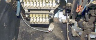
Relay box in the center console
Diagram of an additional relay block on the left side of the center console
Designation and numbering of relays and control units in the center console
Location of the relay box in the car
Designations
| Element no. | vendor code | Purpose |
| 1 | Central locking control unit | |
| 2 | Immobilizer block | |
| 3 | Rear fog lamp relay |