Share:
Here is the tightening torque for a VAZ 2108 car of different thread connections. It includes the tightening torque of the VAZ 2108 camshaft and the tightening torque of the VAZ 2108 car with an 8-valve engine. It includes the tightening torque of the bolts and the tightening torque of the VAZ 2108 hub. The tightening torque of the engine combines the tightening torque of the camshaft and the tightening torque of the cylinder head of the VAZ 2108 8 valves. And the tightening torques for threaded connections of the VAZ 2108 include the tightening torque of the rear hub and the tightening torque of the main VAZ 2108.
VAZ 2108 engine tightening torque
Tightening torque for the cylinder head of the VAZ 2108 engine:
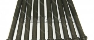
- The M12XI.25 bolts for securing the cylinder head must be tightened 4 times:
- torque - 20 N*m;
- times with force - 6 9.4-85.7 N*m;
- once - turn 90°;
- once - turn it 90°.
- M6 nuts for attaching the cylinder head cover with a force of 1.96-4.6 N*m
Tightening torque of the camshaft of the VAZ 2108 engine 8 valves:
- M8 nuts for studs securing the camshaft bearing housing with a force of 18.38-22.64 N*m;
- M10 bolts for attaching the camshaft pulley with a force of 67.42-83.3 N*m;
VAZ 2108 bolt tightening torque:
- M6 bolts for fastening the housing of assisting devices with a torque of -0.68-0.84 N*m;
- M6 bolts for fastening the oil sump with a force of 5.15-8.23 N*m;
- Hardware M6 for connecting the Tasol pump with a torque of 7.64-8.01 N*m;
- M6 bolts for fastening the supply tube of the antifreeze pump with a force of 4.17-5.15 N*m
Tightening torque for main car VAZ 2108:
- Bolts M10X1.25 for connecting the main bearing caps with a force of 68.31-84.38 N*m;
- M6 hardware for connecting the oil receiver to the main bearing tire with a force of 8.33-10.29 N*m
Tightening torque for VAZ 2108 engine connecting rods:
- Nut M9x1 of the connecting rod cap bolts with a torque of 43.32-53.51 N*m
Tightening torque of the VAZ 2108 flywheel bolts:
- Bolts M10x1.25 for fastening the flywheel with force - 60.96-87.42 N*m
Tightening torque of the crankshaft of the VAZ 2108 engine:
- Bolts M12x1.25 for connecting the crankshaft pulley with a force of 97.9-108.78 N*m
Tightening torque for VAZ 2108 nuts:
- Nuts M8x1.25 for attaching the exhaust pipe of the muffler with a torque of 20.87-25.77 N*m
- Nut M8x1.25 fastening the additional muffler flange with a force of 15.97-22.64 N*m
- Nut M12x1 for connecting the clutch cable to the motor bracket with force - N*m
- M10 nut for the bolt attaching the front propulsion suspension support with a torque of 41.65-51.45 N*m
| VAZ engine tightening torque table | ||
| Name of propulsion devices and parts | Thread | VAZ 2108 engine tightening torque, N*m |
| Stud nuts securing the intake pipe and exhaust manifold | M8 | 20,87-25,77 |
| Tension roller connection nut | M10x1.25 | 33,23-41,16 |
| Stud nuts for connecting the outlet pipe of the cooling jacket | M8 | 15,97-22,64 |
| Nut for connecting the exhaust pipe of the muffler | M8x1.25 | 2,13-2,63 |
| Bolts for connecting the engine front support bracket | M10×1.25 | 32,2-51,9 |
| Nuts of bolts connecting the left motor support | M10 | 41,65-51,45 |
| Nuts for attaching the left engine mount bracket | M10 | 31,85-51,45 |
| Bolt for fastening the rear propulsion suspension support | M10×1.25 | 27,44-34 |
| Nuts of bolts connecting the rear engine mount bracket | M12 | 60,7-98 |
| Bolts connecting the oil receiver to the pump | M6 | 6,86-8,23 |
| Oil pump attachment bolt | M6 | 8,33-10,29 |
| Bolts for attaching the oil pump housing | M6 | 7,2-9,2 |
| Oil pump bypass valve plug | M16×1.5 | 45,5-73,5 |
| Oil filter fitting | M20x1.5 | 37,48-87,47 |
| Oil pressure sensor | M14x1.5 | 24-27 |
| Carburetor attachment nut | M8 | 12,8-15,9 |
Note! 10 N*m = 1 kgf*m
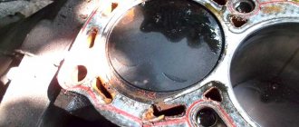
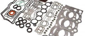
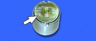
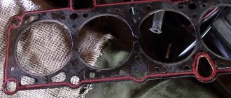
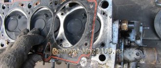
Changing the cylinder head gasket on a VAZ 2109
The cylinder head gasket should be changed if its integrity is visually compromised or its service life has come to an end. Also, the reason for changing the gasket may be leakage of oil or coolant in the areas of the engine block and cylinder head.
To replace the gasket, you need to open the block, remove the old gasket, attach a new one and reassemble the unit. The algorithm of actions will be as follows:
- Disconnect the wires from the cooling system fluid temperature indicator and the emergency oil pressure indicator.
- Pour out the coolant and remove the thermostat.
- Remove the air filter cover (there is no need to remove the carburetor).
- Disconnect the exhaust pipe from the manifold opening.
- Remove the timing shaft gear and place the first piston at TDC, then remove the camshaft boot and loosen the fasteners.
- Remove the drive belt and fasteners.
- Move the wire block lock.
- Turn off the main high voltage.
- Remove the fuel supply cable.
- Disconnect the damper actuators and the approach to the solenoid valve.
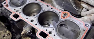
- Remove the vacuum tube and remove the cylinder head.
- Remove the used gasket. Reassembling the parts is done in reverse order.
The procedure for tightening the cylinder head on a nine is a simplified process that can be easily performed with a good theoretical study of this issue. It is very important to perform tightening efficiently and in a timely manner, according to all instructions prescribed by the manufacturer, otherwise you will encounter more serious problems for your machine.
Tightening torque for VAZ 2108 clutch threaded joints
Tightening torque of clutch bolts VAZ 2108:
- Bolts M12x1.25 fastening the clutch housing to the engine block with a force of 54.2-87.6 N*m;
- Bolt M8 attaching the clutch housing to the flywheel with a torque of 19.13-30.9 N*m;
- Bolt M6 fastening the bottom cover to the clutch housing with a force of 3.8-6.2 N*m
| List of devices and connections | Thread | Tightening torque of clutch parts VAZ 2108, N*m |
| Nut securing the clutch housing to the engine block | M12x1.25 | 54,2-87,6 |
| Bolts for connecting the flange of the clutch release bearing guide sleeve | M6 | 3,8-6,2 |
| Nut for attaching the clutch housing to the gearbox | M8 | 15,7-25,5 |
Healthy ! VAZ 2108 diagram
Afterword
Before reassembling the unit, it is necessary to check the condition of all the bolts. If there is the slightest discrepancy, it will be necessary to replace it. It is important to understand that otherwise a good result will be unattainable.
Also, you should not put off replacing the gasket, since such a minor problem will later result in the need to repair the entire power plant. In severe cases, the entire engine may need to be replaced. We also suggest watching the video tutorial:
Source
VAZ 2108 gearbox tightening torque
Tightening torques for threaded connections of the VAZ 2108 gearbox:
- Threaded connection of the drain plug M22x1.5 with a torque of 28.7-46.3 N*m
- Threaded connection M14x1.5 for reverse light switch with force - 28.4-45.3 N*m
| List of devices and parts | Thread | Tightening torque of VAZ 2108 gearbox parts, N*m |
| Conical screw fastening the drive rod joint | M8 | 16,3-20,1 |
| Gear selection mechanism connection bolt | M6 | 6,4-10,3 |
| Shift Lever Housing Fastening Bolts | M8 | 15,7-25,5 |
| Nuts for connecting the drive rod clamp and jet rod | M8 | 15,7-25,5 |
| Nuts of the rear ends of the primary and secondary shafts | M20x1.5 | 120,8-149,2 |
| Bolts securing the forks to the rod | M6 | 11,7-18,6 |
| Differential driven gear mounting pin | M10x1.25 | 63,5-82,5 |
| Speedometer drive housing connection nut | M6 | 4,5-7,2 |
| Metis fastening axis of the gear selector lever | M6 | 11,7-18,6 |
| Nuts connecting the rear tire to the gearbox housing | M8 | 15,7-25,5 |
| Reverse fork lock plug | Ml 6×1.5 | 28,4-45,3 |
| Conical screw for connecting the gear selector rod lever | M8 | 28,4-35 |
| Bolts for connecting the clutch housing and gearbox | M8 | 15,7-25,5 |
Installation of oil seals and oil pump
The 21083 engine lubrication system consists of an oil pump, oil receiver, filter and channels. After disassembling the engine, all channels must be washed with solvent and blown with compressed air. The oil pump should be installed together with the crankshaft seals, and the oil receiver should be installed after installing the ShPG and flywheel.
Installation procedure for seals and pump.
- Using a thick copper or brass spacer and a hammer, drive the rear oil seal into the holder all the way.
- Using lithol or other grease, glue the gasket to the other side of the holder.
- Lubricate the inner edge of the rear oil seal and the crankshaft flange with engine oil.
- We put the oil seal assembly with the holder on the flange; to do this, carefully tuck the inner edge of the oil seal onto the flange using a sharp and soft wooden stick.
Replacing the oil pump seal
- After this, we slowly move the holder along the flange all the way to the cylinder block, secure it with bolts and align it so that its edge completely coincides with the edge of the block. Only after this do we tighten all the bolts completely.
- Just like the rear one, we hammer the front crankshaft oil seal into the oil pump hole.
- Lubricate the inner edge of the oil seal and pump gears with oil. To ensure uniform lubrication, turn the gears with your finger.
- Use lithol or any other consistency to glue the gasket to the oil pump.
- We rotate the drive gear so that the protrusions on it coincide with the cuts on the front of the crankshaft.
- We put the oil pump on the shaft, use a sharp soft wooden stick to tuck the lip of the oil seal onto the crankshaft journal.
- Just like the holder, we move the oil pump all the way to the block, secure it with bolts, align the edges and tighten the bolts completely.
Tightening torque of threaded connections of the front suspension of VAZ 2108
Tightening torque for the VAZ 2108 hatchback hub:
- Nut M20xl.5 for rear wheel hub bearings with a force of 186.3-225.6 N*m;
- Nut M20xl.5 for front wheel hub bearings with a torque of 225.6-247 N*m.
| Name of devices and connections | Thread | Tightening torque of threaded connections VAZ 2108, N*m |
| Nut securing the upper support to the body | M8 | 19,6-24,2 |
| Wing for connecting the ball pin to the lever | M12XI.25 | 66,6-82,3 |
| Nut of the eccentric bolt for attaching the telescopic strut to the steering knuckle | М12Х1.25 | 77,5-96,1 |
| Hardware for attaching the telescopic strut to the steering knuckle | M!2xl,25 | 77,5-96,1 |
| Pins and nuts for connecting the suspension arm to the body | M12×1.25 | 77,5-96,1 |
| Nuts for connecting the brace | M16x 1.25 | 160-176,4 |
| Hardware for fastening the stabilizer bar to the control arm | M10xl,25 | 42,1-52,0 |
| Nuts for attaching the stabilizer bar to the body | M8 | 12,9-16,0 |
| Bolts for attaching the brace bracket to the body | M10x1.25 | 42,14-51,94 |
| Wing for connecting the telescopic rack rod to the upper support | M14x1.5 | 65,86-81,2 |
| Bolts for attaching the ball joint to the steering knuckle | M10x1.25 | 49-61,74 |
| Wheel bolts | M12xl,25 | 65,2-92,6 |
What are plain bearings
To better understand why engine bearings need to be tightened to a certain torque, let's take a look at the functions and purpose of these elements. Let's start with the fact that these sliding bearings interact with one of the most important parts of any internal combustion engine - the crankshaft. In short, the reciprocating motion of the piston in the cylinder is converted into rotational motion precisely thanks to the connecting rods and crankshaft. As a result, torque appears, which is ultimately transmitted to the wheels of the car.
The crankshaft rotates constantly, has a complex shape, experiences significant loads and is an expensive part. To maximize the service life of the element, connecting rod and main bearings are used in the crankshaft design. Taking into account the fact that the crankshaft rotates, as well as a number of other features, conditions are created for this part that minimize wear.
For the manufacture of liners, softer materials are used compared to those from which the crankshaft itself is made. The liners are also additionally coated with an anti-friction layer. Lubricant (motor oil) is supplied under pressure to the place where the liner is connected to the crankshaft journal. The specified pressure is provided by the oil pump of the engine lubrication system. In this case, it is especially important that there is the required clearance between the crankshaft journal and the plain bearing. The quality of lubrication of the rubbing pair, as well as the engine oil pressure in the engine lubrication system, will depend on the size of the gap. If the gap is increased, then the lubricant pressure decreases. As a result, rapid wear of the crankshaft journals occurs, and other loaded components in the internal combustion engine also suffer. In parallel with this, a knock appears in the engine.
Tightening torque for the rear suspension threads of the VAZ 2108
| Name of devices and parts | Thread | Tightening torque of threaded connections VAZ 2108, N*m |
| Nuts for connecting the lower end of the shock absorber | M12x1.25 | 66,6-82,3 |
| Rear suspension arm articulation wings | M12x1.25 | 66,6-82,3 |
| Nuts for fastening the suspension arm brackets | M10x1.25 | 27,4-34 |
| Hardware for connecting the upper end of the shock absorber | M10x1.25 | 50-61,7 |
Step-by-step instruction
If your engine is knocking and you decide to replace the camshaft, then prepare everything you need in advance. It is difficult to carry out this work without relevant experience, so it is good if you are assisted by a more experienced partner.
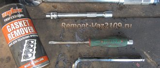
Required Tools
- a set of keys;
- Screwdriver Set;
- torque wrench;
Stages of work
- The first step is to remove the camshaft pulley VAZ 2114 8 cl.
- We take out the pulley key located in the camshaft groove.
- Unscrew the nut that secures the rear cover of the timing belt.
- Unscrew the nuts that secure the bracket to the cable.
- Having loosened the screws of the hose clamps responsible for ventilation of the crankcase gases, we remove them.
- Having loosened the clamp of the hose through which the crankcase gases are ventilated, remove it.
- After unscrewing the nuts, remove the valve cover.
- We remove the gasket.
- After unscrewing the nuts and bolts, remove the plug.
- In several circles (to reduce the spring pressure), unscrew the 10 nuts securing the camshaft bearing housing.
- We remove the camshaft housings VAZ 2114 8 cl.
- After the rear timing belt drive cover is removed from the cylinder head, remove the camshaft.
- Remove the camshaft oil seal.
- Before installing a new shaft, it is necessary to clean the contacting surfaces of the cylinder head and bearings if any sealant or grease remains on them.
- Lubricate the bearing journals and cams with fresh grease.
- We place the shaft in the cylinder head supports so that the cams of the 1st cylinder are oriented upward.
- We apply sealant to the cylinder head planes that come into contact with the bearings.
- We install the bearing housings and tighten the nuts in 2 circles.
- First, we do not completely tighten them as shown in the photo until the bearing housing and the cylinder head are in contact.
- Going in the same sequence around the second circle, we tighten the nuts to a torque of 2.2 kgf/m.
- Remove the leaked sealant.
- We insert the oil seal.
- We install the camshaft toothed pulley and belt drive.
- We turn the crankshaft clockwise to place the same alignment marks on the camshaft pulley and the rear cover of the timing belt drive.
- Rotate the crankshaft about fifty degrees (2-3 teeth on the camshaft pulley).
- Using a feeler gauge, check the gaps at the 1st and 3rd camshaft cams.
- The distance between the cams and washers should be 0.20 millimeters for the intake valves and 0.35 millimeters for the exhaust valves. The error should not exceed 0.05 mm.
- After adjusting the remaining valves, the work can be considered completed.
Steering torque
| List of mechanisms and connections | Thread | Tightening torque of threaded connections VAZ 2108, N*m |
| Steering gear housing fastening nuts | M8 | 15-18,6 |
| Nuts for connecting the steering shaft bracket | M8 | 15-18,6 |
| Steering shaft bracket fastening bolts | M6 | Wrap until the head comes off |
| Bolt attaching the steering shaft to the gear | M8 | 22,5-27,4 |
| Steering wheel mount | M16x1.5 | 31,4-51 |
| Tightening hardware for steering rod end | M10 | 19,1-30,9 |
| Ball pin joint nut | M12x1.25 | 27,05-33,42 |
| Bolts securing the steering linkage to the rack | M10xl | 70-86 |
| Steering gear bearing nut | M38x1.5 | 45-55 |
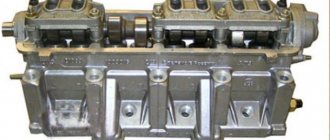
Engine assembly
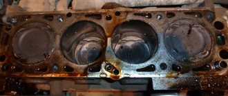
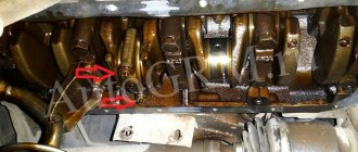
The engine begins to be assembled by installing the main bearings and crankshaft. Nowadays you can come across liners in different configurations, in the photo the liners are not very well equipped as there are no holes on the liner for the central crankshaft journal, and since this journal does not have a through hole, the lower liner will be starved of oil and this leads to faster wear of the crankshaft journal . So don’t be lazy and drill a couple of holes as shown in the photo below.
Photo. Correct installation of liners in the VAZ 21083 engine block.
Before installing the liners in the bed, carefully wipe the bed with a rag so that nothing gets under the liner; debris under the liner can lead to pinching of the crankshaft and poor heat transfer of the liner to the engine block. Install the half rings immediately as shown in the figure, lubricate the inserts with oil, and also lubricate the half rings inside with oil, then they will not fall out of their places.
Photo. The arrow shows the thrust half-rings of the VAZ 21083 engine
After installing the crankshaft into the block, be sure to check the longitudinal movement of the crankshaft, this can be done with a screwdriver as shown in the photo below, insert it from different sides, if there is movement of the crankshaft, then repair half rings are needed. Here you can already select one repair and the other standard, or lightly grind the half ring on a stone or sandpaper spread on a flat surface. Try to ensure that there is no longitudinal movement of the crankshaft; if there is longitudinal movement, the half rings may fall out during engine operation.
Photo. Checking the longitudinal movement of the crankshaft.
Now you need to put the crankshaft cushions in their places, each cushion must return to its place, you cannot install a cushion from another engine as it will be slightly different in the gap and can either clamp or give way. The photo below shows how to install the pillow correctly, note that the lock of the liner is placed next to the lock of another liner, the photo shows the installation of the third pillow with drilled holes. It doesn’t matter whether the holes are beautifully drilled or not, what is important is that oil will flow through them to the crankshaft journal.
Photo. Correct installation of the crankshaft cushion.
Immediately place all the cushions on the crankshaft but do not tighten, tighten the bolts. Now start tightening one cushion at a time, I always start with the third one, tighten it until the crankshaft is tight, turn it with a wrench as shown in the photo below. And so after each tightened pillow, try to rotate the crankshaft. You need to tighten the pillows well, but do not overdo it, as you can break the bolts. You can read more about the crankshaft in the article Repair of the crankshaft (crankshaft).
Tightening torque for VAZ 2108 brake threads
| List of mechanisms and connections | Thread | Tightening torque of threaded connections VAZ 2108, N*m |
| Bolts connecting the brake cylinder to the caliper | Ml 2×1.25 | 115-150 |
| Hardware for connecting the guide pin to the cylinder | M8 | 31-38 |
| Bolts attaching the brake to the steering knuckle | M10x1.25 | 29,1-36 |
| Pin for connecting the rear brake to the axle | M10x1.25 | 34,3-42,63 |
| Wings for attaching the vacuum booster bracket to the bracket booster | M8 | 9,8-15,7 |
| Nuts for connecting the main control unit to the vacuum booster | M10 | 26,5-32,3 |
| Nuts securing the vacuum booster to the bracket amplifier | M10 | 26,5-32,3 |
| Brake pipe joint fittings | M10 | 14,7-18,16 |
| Front brake flexible hose fitting | M10x1.25 | 29,4-33,4 |
How to determine the need for replacement?
Strong noise, humming of the rear hub bearing of VAZ 2109, 2110, “howling” from the rear, increasing when turning, clearly indicates the need to check the condition of the rear hubs. The verification methods are quite simple:
- Be sure to stop the wheel diagonally opposite from the jacking side, and then jack up each rear wheel one by one. (Why each? The fact is that very often there are errors in determining the side of the hum, and even more often there is a need to replace both bearings).
- When the wheel is raised, you need to try to spin it as much as possible. If at the same time you hear extraneous sounds similar to a hum, you don’t have to check further - replacement is necessary.
- if in doubt, you can also check the lateral play of the bearing by grasping the edges of the wheel and rocking it towards you - away from you. If you feel the wheel moving on the axle, the bearing needs to be replaced.
Automotive stores can offer you both a separate bearing and a hub assembly. We see no point in purchasing an assembled unit (except for the cases described below), where replacing the bearing is not at all a difficult matter.
Photo gallery
Photos of the diagram and screw tightening are shown below.
The order to follow when tightening the bolts
Tensioning the cylinder head screws with a torque wrench
Loading …
How to use a torque wrench, video instructions
Conclusions: • A university degree is not required to use a torque wrench. It is enough to understand the quantities in which torque is measured. • Even the most inexpensive model is enough to perform most jobs in your own garage.
Hi all! Lately I haven’t had any time to write on the blog; I’m actively engaged in diagnosing gasoline engines. After watching Pakhomov’s video courses and an in-depth study of the material part of cars, many hitherto uncertainties when repairing car injection systems dissipated and there was a desire to apply knowledge in practice.
I don’t want to seem boastful, but the results are already there and I think they’re good for a start. Sorry for this slight digression from the topic. Today we’ll talk about the topic of torque wrench. What is it and what is it eaten with?
Using a torque wrench
It's no secret that all bolted connections must be tightened to a certain torque. In the literature it is often referred to as newton times a meter. N*m. For example, 10 N*m means that the bolt or nut is tightened with a torque of 10 newtons applied to a 1 meter long arm.
Why do you need to tighten bolted connections to a certain torque? Well, firstly, so that the connection is strong and spontaneous unraveling does not occur. Secondly, when over-tightened, the threads break.
A reader recently sent me an email and asked questions: “How to choose a torque wrench for a car?” and “How to use a torque wrench?” I will answer these questions. But first, let's get acquainted with the types of torque wrenches.
Today there are three types of torque wrenches known. First type.
Pointer torque wrench
This wrench has a handle with a scale, a 1/2-inch square with a ratchet mechanism, and an arrow. The torque wrench scale is marked in N*m or kgf*m in both directions. There is zero in the center of the scale and the arrow of the torque wrench initially points to it. The key handle has a fine knurling for easy holding. This key works on a very simple principle. When the bolt connection is tightened, the metal handle bends (spring steel) and the arrow fixes this bend relative to the scale zero. Everything is very simple.