What is a PCV valve
Theoretically, without this valve, the forced ventilation system cannot work correctly a priori. After all, it is the PCV valve that doses the supply of crankcase gases to the most important area - the space behind the throttle valve, right in front of the combustion chamber.
The PCV valve is not a check valve at all, as many people think. Yes, it is not blown in the opposite direction, but it also does not simply have two positions, open and closed. Everything is much more complicated. Inside the PCV valve there is a plunger loaded with a spring, the force of which is calculated depending on the engine volume, or more precisely, on the vacuum created in the manifold.
PCV Valve Design
The valve has four operating positions:
- The engine is switched off. The valve is completely closed, gases do not enter the manifold, and now they have nothing to do there.
- The engine is running at idle speed. In this mode, the vacuum in the manifold is the highest, the valve is completely open (100%) to ensure the supply of gases (essentially air) into the throttle space. Moreover, the amount of gases is strictly regulated and clearly controlled by the ECU, and the ECU already controls the idle speed controller depending on the amount of air supplied and a number of other factors.
- The engine operates in normal mode at medium speed and medium load. The PCV valve is approximately 50% open. The flow of crankcase gases is average, they burn efficiently in the cylinders.
- Maximum load and high speed mode. The PCV valve is open by 20-25%, the maximum amount of crankcase gases is burned, thereby the pressure in the crankcase is not dangerous for oil seals and gaskets, since it is completely controlled due to the vacuum in the manifold.
Algorithm of operation of the crankcase ventilation valve
On the Lada Vesta, the ventilation system is designed in such a way that in fact it always works the way a normal system works in the fourth mode. The flow of gases is limited only by a 1.7 mm jet built into the throttle pipe. In theory, the expectation was that the system would operate as a dual-circuit system.
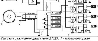
This is how the ventilation scheme is implemented on 8 and 16-valve VAZ engines
The first circuit operates in the speed zone from idle to 1500 rpm. The pipe behind the throttle and the same 1.7 mm jet are involved here. The second circuit is connected to the ventilation already at high speeds, and gases begin to flow into the intake manifold up to the throttle through a hose with a diameter of 18 mm.
Increasing requirements for engine oil separation
A constant increase in combustion pressure due to size reduction, as well as the use of low-viscosity engine oils, leads to a significant reduction in particle size. Accordingly, the performance of installed passive inertial separators becomes insufficient under these limiting factors. New technologies are needed for passenger car applications to provide high separation efficiency for particles well below 1 µm.
Centrifuge – technology for crankcase gas filter
The separation efficiency of small droplets can in principle be increased by increasing the inertial force using additional energy. Centrifuges are well-known examples of this type of separation technology. Here, energy is used to drive some kind of rotor, and particles are separated due to the resulting centrifugal force.
Typically, centrifuges require very high rotation speeds - up to 10,000 rpm. Or alternatively, the structure must be very large, especially to separate particles significantly smaller than 1 µm. Another solution to improve separation efficiency is to use additional mechanisms such as diffusion separation.
Fiber demister – diffusion filter for crankcase gases
The so-called fiber demister is an example of another type of separator that combines the advantages of various additional separation mechanisms. Both mentioned technologies are used in trucks, where the requirements are similar. Meanwhile, fiber demisters can provide an effective solution for use with passenger cars.
FILTERS
Design options for fiber demisters (oil filters), which can be used no less effectively in crankcase gas filtration systems of passenger cars
The demister option allows the crankcase filter to be integrated even into complex designs without compromising performance, while significantly reducing integration complexity and associated costs. Fiber demister elements are usually replaced during the service interval after a certain operating time due to soot deposits on the fiber surface.
The service interval varies greatly depending on the specific application. The main requirement for the suitability of fiber demister for use in passenger cars is the development of new fiber demisters. These provide high performance and an acceptable long service interval under given operating conditions.
At the same time, the pressure drop as well as the dimensions of the fiber demisters must meet the general requirements of a passenger car. Therefore, production, including, is striving to solve this problem. Engineers are developing new fiber demisters for use in passenger car structures.
Crankcase gas filter mechanism with fiber demister
Filter separators are a widely used method in the world for highly efficient separation of ultrafine particles of the same crankcase gases. The droplets combine during the liquid/gas separation process on the surface of the fiber, forming a liquid film that sequentially flows off the filter material.
OBD SCANNER
The principle of gravimetric separation of the contents of crankcase gases: 1 – aerosol form of flow; 2 – penetration; 3 – repeated entrainment (carryover); 4 - drainage
Residual oil droplets on the clean crankcase gas side of the filter are either unseparated aerosol droplets (so-called penetration) or formations in the form of bubbles and caps from the separated liquid film (so-called entrainment). The efficiency of gravimetric separation in a steady state is calculated by the formula:
Ng = 1 – (Mp + Me / Md + Mp + Me)
where: Ng – efficiency of geometric separation; Mp – penetration; Me – hobby; Md – drainage.
Various types of separation mechanisms are used generally in accordance with the theory of crankcase gas filtration of automobile engines. For crankcase ventilation (filtration of crankcase gases), the appropriate separation mechanisms are, in particular:
- blows,
- diffusion,
- interception
The efficiency of separation based on impact and interception effects increases with increasing particle size, while the efficiency of separation based on diffusion effects increases with decreasing particle size.
Schemes for upgrading the crankcase ventilation system
Schemes for modifying the crankcase ventilation system, as well as a description, are provided by IgorRV.
For LADA cars with manual transmission and AMT (“robot”), scheme No. 1 “Crankcase ventilation scheme with PCV valve for E-GAS and cable throttle” is suitable:
It is necessary to install a PCV valve (article 94580183, price about 400 rubles) from a foreign car into the small crankcase ventilation circuit. When connecting the PCV valve to a small circuit on an E-GAS, use a new hose (petrol-oil-resistant 8 mm without fabric reinforcement). On a cable choke, connect to the receiver, not to the choke.
As a result, the valve will shut off the circuits in transient modes, which will allow:
- Accept the load without jerking or dropping engine speed (for example, when the compressor is running, heated windows, seats, etc.).
- Reduce vibration load at idle
- Increase traction from the bottom (noted by owners of automatic transmission with VAZ-21126 engine, manual transmission with VAZ-21227, 21126 and 11186 and AMT with VAZ-21127).
- Get a sharper response to the gas pedal and faster shifts (on AMT). Perhaps due to the fact that the valve does not allow the engine to slow down, maintaining a more optimal switching algorithm.
- Reduce oil consumption through ventilation.
The valve replacement period is 40,000 km.
For LADA cars with automatic transmission (Jatco) and AMT (“robot”), scheme No. 2 is suitable:
Description of scheme No. 2: The pressure reducing valve is connected in series to a large ventilation circle. Thus, it regulates the flow of crankcase gases at high speeds and during transient processes. This allows:
- Exercise full control over the flow of crankcase gases between the small and large circuits.
- Improve engine operating mode.
- Reduce vibration load.
- Reduce oil release into ventilation.
For LADA cars with automatic transmission (Jatco) and AMT (“robot”), scheme No. 3 is suitable:
Description of scheme No. 3: To improve the operation of the braking system and facilitate the process of holding the car on the brakes in mode “D”, an “Ejection Pump” was used. Due to the flow of crankcase gases from the small circuit, the vacuum in the tube leading to the vacuum booster increases. This happens at low speeds, which is very helpful when driving in traffic jams. Keeping your foot on the brake all the time is not very easy, but this pump makes the task easier.
- Getting rid of vibrations, failures, transmission shocks.
- The engine begins to operate more calmly and softly.
- The force on the brake pedal becomes less.
- The air conditioner turns on almost imperceptibly.
Required:
- ejection pump (article 10793 VIKA, price 546 rubles);
- pressure reducing valve (article 1117701500 JP GROUP, 422 rubles);
- PCV valve (article 94580183 GENERAL MOTORS, 400 rubles);
- clamps (about 10 pieces, 600 rubles);
- thin, petrol-resistant 8 mm hose 50 cm (100 rubles);
- standard ventilation pipe.
Installation example on video:
By the way, there are other ways to modify the crankcase ventilation system. Are you ready for such modernizations? Let us remind you that modification of the ignition system (installation of capacitor ignition coils in the harness) is also common among owners of LADA cars.
Keywords: lada xray engine | Lada Vesta engine | Lada Largus engine | Lada Granta engine | Lada Kalina engine | Lada Priora engine | Niva engine | universal article
14
1
Found an error? Select it and press Ctrl+Enter..
The Lada Largus subframe was modified at the factory
Installing a rear view camera on Lada Granta, Priora and Kalina
What to do if the stove does not heat well on the Lada Vesta and XRAY
Correct sound insulation of car wheel arches with your own hands
Brief information
The valves have a simple design and are highly wear-resistant. The latter is due to the manufacturing material, which must withstand increased loads.
The valve itself consists of several sections:
- plates (lower expanded part of the part);
- rod (the upper narrow part of the part, going from the plate upward);
- chamfers (the place where the plate adheres to the cylinder block);
- plate edges;
- the end of the rod (its upper part located above the groove);
- recesses for crackers (small groove under the end).
The contact point between the plate and the cylinder head is called the seat. It is made of steel or cast iron and pressed into the cylinder head.
According to their purpose, valves are of two types:
Inlet
Responsible for supplying the air-fuel mixture to the cylinder-piston system. They have a solid rod and, usually, a larger diameter plate to improve working properties.
High school graduation
Responsible for the removal of exhaust gases during the operation of the internal combustion engine. The stem of this type of valve is made hollow; Sodium is placed inside it. This design allows the exhaust valve to be cooled, since it is subject to higher heat than the intake valve. For its production, heat-resistant metal is necessarily used.
Why is there a need to replace valves?
Under normal operating conditions, valves may need to be replaced due to wear. This happens after about 300 thousand km.
There are usually two reasons for the need for unscheduled replacement: burnout and deformation.
Premature burnout can happen due to:
- constant driving at the highest possible speed and, as a result, a knocking engine;
- frequent refueling with low-quality fuel;
- incorrectly adjusted gap (the gap is too small and the heat dissipation is impaired);
- inappropriate number of spark plugs, etc.
The valve becomes deformed when the timing chain breaks or when it moves several links (this happens when the tension is poor). As a result, the rod bends, which leads to a loose fit of the plate to the seat.
The second method of upgrading crankcase ventilation
The meaning of the following is to transfer the small ventilation circuit from the throttle part to the receiver, which helps reduce differences when switching modes. To complete this design, you will need to perform the following manipulations:
- The thin crankcase ventilation hose is disconnected from the throttle;
- The free end is connected to the free inlet fitting on the receiver, with preliminary removal of the plug;
- The free opening of the remote control is blocked by installing a plug;
- As a result, the flow of air mass increases, eliminating the possibility of a sharp response of the throttle valve to a jerk of the engine;
- In addition, crankcase ventilation increases and additional draft appears in the lower part of the mechanism.
How to clean the crankcase ventilation system on a VAZ 2110-VAZ 2112?
Note! Before you start work, remove the air filter housing, as it will interfere greatly; if you do not know how to do this, then read the article entitled: “Replacing the air filter housing on dozens”!
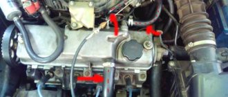
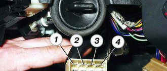
Removal: 1) The hardest thing is to remove the cylinder head cover, but the remaining parts that relate to the ventilation system (And these are mainly hoses), removing is as easy as shelling pears, in general, let's start, first you will need to disconnect the wires from each other, namely the upper connectors (see photo 1 ) and lower connectors (Indicated by a red arrow), once this is done, remove the connectors, to do this, squeeze the two latches on one connector with your fingers and remove it (see photo 2) and do the same with the other connector, just without removing it, they will interfere, and in general you won’t be able to remove the cylinder head cover without removing these connectors, because the wires simply won’t allow you to do this, both connectors were sitting on brackets, so unscrew the bolts securing them and remove both brackets from the cylinder head cover, in more detail how to do this , look at photos 3 and 4 below.
2) Now remove the exhaust manifold from the cylinder head cover, it is bolted on and by the way, when you remove it, replace all the O-rings, firstly they are not expensive and secondly, after replacement, you will be 100% sure that the collector will not let air through anywhere, since the rings will be new; you can read in more detail how to do this in the article entitled: “Replacing the receiver on a 16-valve car.”
3) Then start removing the hoses, they are held in place by clamps, the clamps are loosened using a screwdriver or wrenches, if it is not convenient to work with a screwdriver, all the clamps that you will need to loosen and all the hoses that you will need to remove, you can see in the photographs a little below:
Note! Rinse the removed hoses with gasoline or kerosene, then dry them in the sun and, if possible, also blow them with compressed air (for example, a compressor), before installation, make sure that the hoses are dry, if necessary, wipe them dry with a rag and by the way, Carefully clean all those places where the hoses are connected with a cloth and remove all dirt from them!
4) When everything is finished, remove the cover from the Cylinder Head, it is secured with fifteen bolts, these bolts are unscrewed with a socket wrench or a socket head and an “8” wrench, then the cover is separated from the cylinder head with a screwdriver and removed from the car, it is most convenient to separate it from the cylinder head in those places where there are special protrusions for this, one of such protrusions is indicated by a blue arrow.
5) After you have the cylinder head cover in your hands, using a wrench or a socket wrench, unscrew the six bolts that secure the separator to it (Several bolts are indicated in the large photo) and disconnect it from the cover (see small photo).
Note! This separator is an integral part of the crankcase ventilation system, it has such a part as an oil deflector, to pull it out, you will need to compress the side clamps using pliers (see photos 1,2), a rubber o-ring will be installed on the oil deflectors, picking it up with a screwdriver , you also need to remove it (see photo 3,4) and replace it with a new one, if such a ring is difficult to find in car shops, then you are allowed not to change it if it is in good condition, namely: It should not be too compressed, the rubber is not should become rough and lose its elasticity, and there should be no cracks or other types of damage on the ring!
Installation: Installation of all parts is carried out in the reverse order of removal, but before installation, wash everything thoroughly with gasoline or kerosene, this also applies to the cylinder head cover itself, there should be no dirt on it, and also remove old sealant (with a screwdriver or fine-grained sandpaper) the surface where the cylinder head cover is installed, after cleaning, degrease it and apply a new sealant, as it is shown in the small photo below:
Additional video: An interesting video that will give you a little additional information on the crankcase ventilation system is located just below:
Source
Lada 2114 0-day › Logbook › Do-it-yourself oil catcher.
Hi all! There have been no posts for a long time. I will slowly improve. I’ll probably start with a note about “oil in the trash.” At high speeds, a lot of pressure is created in the “head” and it carries oil through the breather into the air filter, which is not good. As a result, the mass air flow sensor begins to suffer and the throttle becomes clogged (the speed fluctuates). Well, as they say, why not make this product for yourself.
— Power steering reservoir from the Volga (metal). — Two “L”-shaped fittings for the level. — Drain tap. — 4 metal sponges. — 2 hoses.
I sanded off the excess solder with a file and then sandpaper.
I made a drain valve in the bottom cover.
Everything was ready with the tank. All that remained was to make the mount. Since I have an adsorber on the right, I had to do it from the opposite side. I cut out two plates from a 2mm piece of iron and welded them to each other.
Then all that was left was to prime and paint the whole thing.
Well, here is the finished version, fully assembled.
Then I filled the tank with sponges, glued bitoplast and splen around the mount and at the points of contact with the body.
Then I took the whole thing to the car and installed it safely. I also installed a fuel filter on the small circle, I will monitor the changes.
UPD.
After a trip to Saratov, 3 days after installation, I had to redo the mount and strengthen it.
UPD2.
I change the small circle filter every 1000 km, during which time several drops of oil accumulate in the filter, and the filter itself begins to deform from the manifold. There is also a little oil on the large circle, but just a little at the bottom. So it’s a completely working thing, because oil doesn’t fly into the intake.
After assembly, I went to the track and turned the engine properly. I arrived home, the tank and fuel filter are dry at the moment. The positive thing I have found so far is that the revs have become more even.
Thank you all for your attention and good luck on the road!)
Source
Design and principle of operation
As was said at the very beginning, the ventilation system removes crankcase gases from the VAZ 2114 back into the engine, preventing unburned fuel oil mixture from entering the atmosphere. It includes a pair of pipes through which gases are removed, and a filter that traps solid particles and clots.
The principle of operation of the crankcase ventilation system of the VAZ 2114
The whole system functions as follows:
- the fuel mixture entering the engine burns and forms exhaust gases, most of which are discharged from the engine into the exhaust line;
- a small part of the gases leaks through the piston rings and enters the lower pipe of the ventilation system;
- From the lower pipe, gases enter the filter (made in the form of a multilayer mesh), after which, already purified, they return to the engine, where they burn out.
Stories from our readers
“Fucking basin. "
Hi all! My name is Mikhail, now I’ll tell you a story about how I managed to exchange my two-wheeler for a 2010 Camry. It all started with the fact that I began to be wildly irritated by the breakdowns of the two-wheeler, it seemed like nothing serious was broken, but damn it, there were so many little things that really started to irritate me. This is where the idea arose that it was time to change the car to a foreign car. The choice fell on the melting Camry of the tenth years.
Yes, I had matured morally, but financially I just couldn’t handle it. I’ll say right away that I am against loans and taking a car, especially not a new one, on credit is unreasonable. My salary is 24k a month, so collecting 600-700 thousand is almost impossible for me. I started looking for different ways to make money on the Internet. You can’t imagine how many scams there are, what I haven’t tried: sports betting, network marketing, and even the volcano casino, where I successfully lost about 10 thousand ((The only direction in which it seemed to me that I could make money was currency trading on the stock exchange, they call it Forex. But when I started delving into it, I realized that it was very difficult for me. I continued to dig further and came across binary options. The essence is the same as in Forex, but it’s much easier to understand. I started reading forums, studying trading strategies. I tried it on a demo account, then opened a real account. To be honest, I didn’t manage to start earning money right away, until I understood all the mechanics of options, I lost about 3,000 rubles, but as it turned out, it was a precious experience. Now I earn 5-7 thousand rubles a day. I managed to get the car buy after half a year, but in my opinion this is a good result, and it’s not about the car, my life has changed, I naturally quit my job, I have more free time for myself and my family. You’ll laugh, but I work directly on the phone)) If If you want to change your life like me, then here’s what I advise you to do right now: 1. Register on the site 2. Practice on a Demo account (it’s free). 3. As soon as you get something on the Demo account, top up your REAL ACCOUNT and go to REAL MONEY! I also advise you to download the application to your phone, it’s much more convenient to work from your phone. Download here.
Analogues (manufacturers)
Of course, the manufacturer and many automotive experts recommend installing the original valve cover gasket, but, as practice shows, substitutes are often of higher quality and have a much longer service life.
So, let's look at which analogues of the original part are recommended for installation on a car:
As you can see, the cost of alternative gaskets is quite high, but as practice has shown, the service life of the parts is twice as long as the original.
Engine crankcase ventilation system
It would seem that the operation of the internal combustion engine itself serves as a source of severe air pollution, and we are trying to talk about ventilation here. However, not everything is so simple; the engine, like everyone else, also needs fresh air. It is also provided by the crankcase ventilation system.
About the purpose of the ventilation system
All problems, as always, are hidden in the little things. In this case, this concerns the existing gaps between the piston and the engine cylinder block. It would seem that the design provides special elements that minimize these gaps. And yet, despite the sealing rings, fuel combustion products, its unburned particles, and water vapor enter the engine crankcase volume. The consequence of this is a deterioration in the quality of the oil and loss of its lubricating properties. A similar effect manifests itself in the fact that ordinary oil becomes a water-oil emulsion, and it also liquefies.
It is to prevent such phenomena described above that the crankcase ventilation system is designed. It allows you to remove escaped exhaust gases from it, ensure normal pressure, thereby increasing the reliability and durability of the engine.
How does crankcase ventilation occur?
As always in such cases, there is a choice.
The implementation of this system can be of two types:
- open;
- closed.
In the first case, when the engine crankcase ventilation system is open, the exhaust gases that have broken through are removed outside the power unit. The simplicity and low cost of this method is compensated by environmental pollution.
In addition, you should know that open ventilation:
- does not work at low speed and at idle;
- does not cope with its duties at high speeds;
- through it it is possible to suck in atmospheric unfiltered air when the engine cools down;
- may be one of the reasons for increased oil consumption, as well as a reason for oiling of the engine.
Closed or forced crankcase ventilation is carried out when trying to reduce the degree of pollution caused by the car. For this purpose, a special valve is installed, thanks to which, during forced crankcase ventilation, the exhaust gases that enter there are discharged into the engine intake manifold.
increased contamination of the carburetor and inlet air ducts; strong draft at high speeds in the exhaust gas suction system, which can serve as an additional reason for oil oxidation.
The advantages include:
- reduced oil consumption;
- stable operation in winter due to heating of the inlet air by crankcase gases;
- they also increase the engine’s knock resistance by diluting the fuel-air mixture.
Options for creating forced crankcase gas cleaning
The truth is that not everything is as simple as it seems at first glance. There are two approaches by which forced crankcase ventilation can be performed. Exhaust gases can be removed from the crankcase, and perhaps the opposite effect is the flow of air from outside.
An indispensable attribute of a modern internal combustion engine is crankcase ventilation, most often designed as a closed system. It allows you to increase the reliability of the engine and reduce the negative impact of vehicle exhaust on the atmosphere.
Why is cleaning necessary and its frequency?
When the ventilation system is clogged, an emulsion containing soot and oil residues settles inside the engine, resulting in the creation of excess pressure, leading to damage to the seals. This leads to loss of sealing and oil leaks, which can be seen during an external inspection of the engine block. Crankcase gases are gases from engine cylinders that are not discharged through the exhaust valve, but are squeezed out into the crankcase through the gaps of the pistons and piston rings when the engine is running. This process occurs especially intensively in worn-out engines with high mileage. For VAZ 2101-2107, these are mileages of 80-100 thousand km.
If the crankcase ventilation is not cleaned in a timely manner, the operation of the fuel supply system will be affected. In carburetor engines, the air filter and the carburetor itself become dirty; in injection engines, the throttle assembly, inlet pipe and sensors become dirty. All this leads to a decrease in power, problems with operation, and in some cases a complete stop of the engine. To avoid this, additional elements are introduced into the ventilation system to clean crankcase gases from emulsions containing oil.
If the crankcase ventilation system is not cleaned in a timely manner, the hoses crack due to excess pressure. This causes excess air to be sucked into the engine. Carburetor engines are not so sensitive to this problem, but in injection systems the quality of the mixture sharply deteriorates, the stability of the engine is disrupted and its power is reduced.
The best option is to clean the crankcase ventilation on a VAZ classic immediately before changing the oil. This frequency allows you to keep the system in order, change cracked hoses on time, extend the life of the engine, and reduce fuel consumption without loss of power.
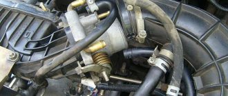
SVKG device in Lada Priora
In all brands of cars, the SVKG is built on a similar principle. Only small details differ. On the upper side of the crankcase there is an oil separator, which looks like a hollow plug. An oil deflector is placed under the plug, which is designed to clean the gases from the crankcase as much as possible from oil particles. The oil separator has an outlet for the crankcase ventilation hose.
In order for the gases to return to the cylinder chamber, a ventilation valve is placed along their path. The valve has three modes, which allows you to maintain a certain level of gas rarefaction in the crankcase.
While the engine is idling, gases move through a small circuit hose through a special passage hole in the throttle assembly. At this time, a high vacuum is created in the intake hose, which allows crankcase gases to be effectively sucked out of the throttle block. The passage hole in the throttle regulates the amount of gases that are sucked out.
This allows you to stabilize the engine in idle mode. When the car begins to move, the throttle valve opens, causing gases from the crankcase to enter the cylinder through a large circuit hose for combustion.
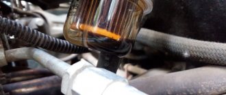
Breather oil: what to do and how to find the cause
Let's start with the fact that during engine operation, so-called crankcase gases accumulate in the crankcase. To prevent excess pressure from being created, there is a special valve for ventilation. This solution allows the closed crankcase to communicate with the atmosphere. This valve is the breather. In simple words, a breather on an internal combustion engine is actually needed to equalize the pressure inside the engine.
It should be noted that in the crankcase gases mix with oil mist. As a result, lubricant particles enter the breather. Although there is a special oil trap inside the device, a certain part of the oil may escape out. Given this information, minor contamination of the system is acceptable, which is normal. In cases where a lot of lubricant leaks, you should look separately for why oil is leaking from the breather.
On injection engines, traces of oil getting into the throttle area are noticeable, the power unit also loses its throttle response and power, and fuel consumption increases noticeably. It turns out that to check it is necessary not only to inspect the outer surfaces under the hood, but also to remove the air filter, throttle assembly, etc.
How often should cleaning be performed?
If the ventilation system is clogged and its filter is unable to clean the mixture passing through it, then not only unburned gases, but also oil particles and other pollutants will enter the engine. All this will ultimately have a negative impact on both the operation of the engine and its remaining service life.
The frequency with which the crankcase ventilation of the VAZ 2114 should be cleaned directly depends on the condition of the engine. So, if the car just recently came off the assembly line, and its engine has not clocked up 50,000 km, you shouldn’t even think about cleaning it, since the piston rings are still new, and there is practically no leakage of gases through them.
Valve cover of VAZ 2114 engine
The first cleaning (as recommended by AvtoVAZ itself) should be performed after the car has covered 60,000 km. And all subsequent cleanings should also be performed after every 60,000 km.
Cylinder head repair
We mark all hydraulic compensators with numbers using an ordinary clerical touch and put them away. An ordinary magnet will help you pull them out. We dry out the valves and remove the oil seals (valve seals), the valves into scrap metal, the oil seals into the trash. We clean all channels. We take the head for grinding, just in case. After washing it again with kerosene after sanding and blowing it with air, we begin to assemble it.
We arrange the freshly purchased valves in the sequence in which they will stand in the cylinder head and begin to grind in one by one. Lubricate the valve stem with clean oil and apply lapping paste to the edge.
We insert the valve into place and put a valve grinding tool on the valve stem. The stores sell a device for manual lapping, but since this is the twenty-first century, we are mechanizing the process. We take the old valve and cut off the rod from it, select a rubber tube for it of such a diameter that it fits tightly. The rod is in a reversible drill, one end of the tube is on it, the other is on the valve being ground in. At low speeds we begin to grind the valve, constantly change the direction of rotation and periodically press it to the seat or weaken the force. On average, the valve takes about twenty seconds. We take it out and wipe it. The valve is considered ground in if a uniform gray strip of at least 1.5 mm wide appears on the chamfer.
The same stripe should appear on the valve seat.
Crankcase ventilation system Kalina 8kl
Today we’ll talk about the crankcase ventilation system on Kalina with an 8-valve engine. And to be more precise, about cleaning this system. Crankcase gases straight from the crankcase (hence the name) are sent mixed with air to the intake manifold for re-burning, thus saving a certain percentage of fuel. So, along with the gases, oil particles enter the system and clog it.
It is this oil that needs to be cleaned from the crankcase ventilation system. Over time, plaque forms on the walls of the hoses, which impedes the passage of gases.
In the Kalinovsky engine, in the valve cover, there is a special separator that separates crankcase gases from the oil. It gets clogged the most. So, let's get started. The entire ventilation system consists of 3 pipes. We need to unscrew them.
Then remove the valve cover. There are two bolts on the back side, unscrew them and get to the separator.
- The easiest way to clean it from oil and deposits is in a bath of gasoline or solvent.
While the separator is acidifying, you can work on the pipes. In general, if they are heavily soiled, it is advisable to replace them with new ones. In my case, I replaced only one - coming from the valve cover to the air filter pipe. The rest were washed with carburetor cleaning fluid (great stuff, it corrodes absolutely everything). The separator itself can also be washed a second time with this thing.
We wipe everything with a clean cloth and put it back together as it was.
Pay attention to the condition of the valve cover gasket. It is considered disposable and it is better to replace it with a new one each time you remove it in order to avoid oil leaks.
Modification of the crankcase ventilation system Kalina 8 valves
This system could be improved a little. One of the 3 pipes supplies crankcase gases directly to the throttle valve assembly next to the IAC. If they contain oil, it will definitely settle there. This is how the IAC becomes clogged. So, to avoid this, you can embed a regular fuel filter right in the middle of this pipe.
It will trap oil particles contained in crankcase gases. After a few hundred kilometers, you will see for yourself. Monitor the condition of this filter and promptly change it to a new one. On average, as practice shows, it needs to be changed every 1000 kilometers.
Replacing valve stem seals - pro tips
I decided to replace the valve stem seals, the reason was the spark plugs, or rather their condition, and recently there was smoke when starting up when cold and too much oil.
As they say: the eyes are afraid, but the hands do)))
As it turned out later, the cause of the plaque on the fourth spark plug was the caps falling off, both of them.
Prepared the tool
An approximate list of what is needed.
Unscrew and disconnect everything that gets in the way, remove the valve cover.
We remove the camshaft pulley, two housings, and the camshaft itself.
We remove oil and dirt.
We provide access to the crankshaft pulley and set the top dead center of cylinders 1 and 4.
We fix the valve we need with tin.
TRIALLI valve stem seal set from old stock.
Bushings for putting on, so as not to damage the grooves of the cracker. You need to remove the spring from the seals and dip them in oil.
We change the seals on cylinders 1 and 4.
We put on the bushings and the seals themselves.
We press in the bushing and put on the springs.
We put the pushers and adjusting washers in their place, the main thing is not to mix them up.
We turn the crankshaft and do the same with the 2nd and 3rd cylinders.
Lubricate all rubbing elements with oil.
At the same time I changed the camshaft seal, just in case)))
We install the camshaft, the cams of the first cylinder should point to the sides, put on the oil seal and apply sealant to the corners.
On the other hand, it also needs to be lubricated with sealants.
We install a new lid ring, lubricating it with sealants.
We install the camshaft housings, rear cover and pulley, not forgetting the key.
We catch the mark on the flywheel
Place a mark on the pulley, put on and tension the belt
To put your mind at ease, you can check the gaps)
We collect and connect everything necessary to start the engine, then we try envy.
If all is good.
We install and screw everything else... and that's it)))
On cylinder 4, both caps fell off, on the rest, the exhaust caps were removed by hand, and the intake caps were removed with a puller; all caps were hard.
After the replacement, there were already a couple of morning starts and I didn’t notice any smoke like before), I also unscrewed the spark plugs and everything was fine too. In general, everything seems to be good, I think time will tell.