You won’t be able to ride much in the cold season with a non-working stove, so repairing it won’t be shelved. If you don’t want to turn to specialists, but want to do everything yourself, then you will initially need to study the design of the Priora stove without air conditioning or with air conditioning, depending on the car model. The electrical circuit of the Priora heater also requires attention.
How the stove works on the Lada Priora
The Lada Priora has two systems that are responsible for creating and maintaining comfortable conditions inside the cabin. This is a heating system and ventilation system, which includes the following elements:
- heater;
- a fan that is synchronized with the stove;
- interior temperature sensor;
- air distribution housing;
- deflectors.
The heated air flows from the heater into the air distribution housing, after which it is directed to the corresponding air ducts. This way the heat is distributed throughout the cabin:
- to the air vents on the windshield and side windows;
- to the deflectors in the center and side of the dashboard;
- to warm your feet.
Malfunctions
For normal operation, the heating system needs: tightness, integrity of parts and normal antifreeze. The first step is to check the relay and fuse - after all, this unit contains electrical appliances inside. If the unit's electrical network is not in contact with the ECU, there is no point in turning the controls on the heater control unit.
The heater fuse on Priora has the number F9. In order to get to it, you need to remove the plastic plug above the driver's left knee (under the headlight switch) by unscrewing three bolts around its perimeter.
Once the fuse has been inspected and no deficiencies have been identified, further diagnostics can begin.
Perhaps the most annoying thing in any car is the situation when, even at the hottest summer temperatures, the heater does not turn off. This happens because the damper does not block the air flow. The heater damper on the Priora is controlled by a gear motor, which stops after its operating life has expired - it will have to be replaced.
While driving a VAZ-2170, you should carefully look and listen to what you see and feel. If heat should come from the cracks, but it doesn’t, then something is wrong with the seal or the damper gear motor. For example, if the glass becomes greasy, as if it was smeared with your hands, it means that the heater radiator is leaking. However, these are not the only signs of a heater failure.
Priora: the stove blows cold air, does not heat - reasons
When cold air comes from the heating system and turns into the air conditioner, the following possible malfunctions are considered:
- The heater hoses do not supply coolant, or the radiator itself is not efficient enough and does not take heat from them.
- The air filter is dirty. If there is no new part nearby, try removing the filter and then starting the heating system without it.
- The damper gear motor is stuck.
- The control unit (switches) is broken.
- The temperature sensor in the cabin has broken (it is located under the roof).
The shutter does not move, and the modes: face, legs, glass do not work
Reasons for this problem include:
- Faulty air distribution gearmotor.
- Inoperative control controller (CU).
The stove blows hot air when turned off.
The most likely reason for this behavior of the heater is a failed damper gear motor.
It’s noisy – what to watch
When you hear an unknown noise, you need to check the heater motor bearing. The noise is caused not so much by the bearing, but by small debris that has gotten under the motor blade.
The stove does not blow and does not even turn on
There are only two reasons why air does not escape from the heating system of a Lada Priora car. When the interior heating does not work, you need to check fuse F9 and the switches on the center console - perhaps they are simply broken.
Priora stove diagram
What is included in the heating system
The heater is located in the engine compartment in the area of the right windshield trim. It is attached to the front panel. The entrance to the heating system is occupied by a filter, which is responsible for cleaning the air used for heating and ventilation.
The design of the Priora stove consists of a number of elements:
- filter cover;
- filter, which is used for heating and ventilation;
- heater housing;
- micromotor gearbox;
- radiator;
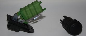
- additional resistor on the fan;
- fan.
Principle of operation
In addition, the Priora heater device includes important components, without which normal operation of the stove would be impossible. These include the following mechanisms:
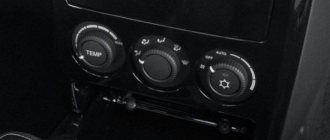
- The operation of the control unit is based on turning the knobs, each of which is responsible for one or another system parameter.
- The cabin temperature sensor allows you to maintain the required temperature at a constant level. This mechanism is located in the headliner trim.
- The additional resistor is located in the fan housing along with the fan, radiator, filter and damper.
- The radiator is connected through hoses to the system that cools the engine. During vehicle operation, coolant circulates from the engine to the radiator all the time. The heater is controlled by a damper, which changes the direction of outside air, directing it towards or past the radiator. The damper can be located in an intermediate position, which provides for the division of the external air flow: one part is directed to the radiator, and the other passes past it.
- The micromotor is responsible for controlling the movement of the damper. It is located on the left side of the body. The micromotor gearbox has an output shaft, which is connected to the axis on the damper.
This is exactly the design of the Priora stove (2010). But we have not yet considered all working issues.
Air flow distribution
As mentioned earlier, the heated air is distributed throughout the entire cabin, rather than blowing at one point. This heating turns out to be more efficient. Such heating features are provided for by the design of the Priora heater. The following elements are responsible for performing these functions:
- air ducts from the side deflector and glass blower;
- air distribution housing;
- flap;
- damper gear motor;
- air duct for blowing feet.
conclusions
At this point, we can consider the problems of the furnace device on your car to be fairly fully resolved. Almost any motorist who has studied the principle of its operation can repair the stove on a Lada Priora. In the future, the maintenance process consists of sequential diagnostics of its structural parts according to the above diagram. Most faults, such as cold air flows, insufficient heating and others, have a very clear diagnosis, which makes it quite easy to localize and fix the problem.
Many people guess what a heater radiator is for the Priora cooling system, but everyone knows for sure. The people for this heater have their own name: stove radiator. This means that it is primarily used during cold periods, when the air passing through the heater radiator is heated and supplied to the passenger compartment. And if so, then they remember about this same heater radiator at the worst possible moment, when it’s already winter and cold outside, then repair work and research begins on how to replace it, and where to look and fix it. In fact, “how” and “what” are also an important factor, because without certain knowledge you cannot get into the Priora system, it will be of no use except wasted time. So, in order to make it clearer to you what and why, and also to make it easier to repair your stove on the Lada Priora, we have prepared this article. Kommersant By the way, it’s not only about the stove, but also about the air conditioning system and the air conditioner, so what about We'll talk about that too.
1. Design features of the stove-heater Lada Priora VAZ 2170 2171 2172 (Lada Priora)
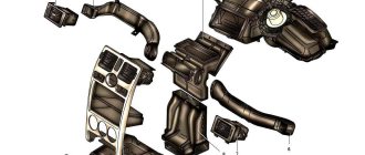
The Priora car is equipped with a liquid-type heater (Fig. 1), combined with an engine cooling system. Main elements of the heater:
– heater heat exchanger (radiator), designed to heat the air entering the passenger compartment with the heat of the engine cooling liquid; – an electrically driven fan (supercharger), providing a controlled supply of outside air to the heater dampers; – a damper for the air temperature regulator coming from the heater into the passenger compartment, the position of which determines the amount of air passing through the heat exchanger of the heater, and the amount of outside air passing bypassing the heat exchanger; – air heating distributor dampers 4, which distribute the air entering the cabin from the heater through air ducts 2, 6, 8 and 9 or for blowing the windshield.
Rice. 1. Ventilation and heating system for the interior of a Lada Priora car: 1 – left side ventilation nozzle; 2 – left ventilation air duct; 3 – side window heating nozzle; 4 – air heating distributor; 5 – heater; 6 – right ventilation air duct; 7 – right side ventilation nozzle; 8 – air duct for heating legs; 9 – interior heating air duct; 10 – central ventilation nozzle.
In turn, the presented components of the Pyrora stove can be divided into components. Let's start with the distribution block.
Now let’s take a look at what the stove heater consists of, which, like in the tenth family, is installed on the engine compartment side, that is, it is mounted and removed from the engine side.
1, 3 — housing parts of the Priora heater, 2 — air filter, 4 — gear motor, 5 — heater radiator, 6 — sensor, 7 — heater (heater) fan.
Figure 2 The main elements of ventilation of the central part in a Lada Priora car..
Figure 3 the main elements installed on a Lada Priora car (with air conditioning) to maintain the climate in the car.
2. Operations performed when removing and installing a heater (stove) on a VAZ 2170 2171 2172 Lada Priora
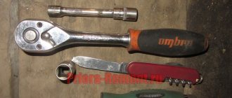
You will need: an “8” wrench, “10”, “13” socket wrenches (head), a Phillips-blade screwdriver, side cutters. 1. Disconnect the wire from the negative terminal of the battery. 2. Remove the windshield frame linings (see “Removing and installing the windshield frame linings on a VAZ 2170 2171 2172 Lada Priora”) and the sound-proofing upholstery of the engine compartment (see “Removing and installing the sound-proofing upholstery of the engine compartment on a car VAZ 2170 2171 2172 Lada Priora (Lada Priora)"). 3. Loosen the clamps...
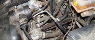
4. ...and disconnect the hoses from the heater radiator pipes.
Helpful Hints When the hoses are disconnected, some coolant will leak out. Place a container under the radiator hoses to catch any spilled liquid. Plug the radiator pipes and hoses immediately after disconnecting the hoses.
5. Press the latch...
6. ...and disconnect the heater fan wiring harness connector.
7. Disconnect the wiring harness connector from the additional resistor.
8. Cut the clamp securing the wiring harness to the heater.
Lada Priora with air conditioning
The electrical circuit of the Priora stove with air conditioning is somewhat different from the option discussed above, because in this case another complex mechanism is added. There are two types of air conditioners installed on Prioras:
- "HALLA" is produced in Korea;
- Panasonic is made in Taiwan.
To immediately determine the brand of the air conditioner that is installed in your car, you need to pay attention to the button in the center of the control unit. Panasonic air conditioners have a power button, but Halla does not have such functionality.
The layout of the Priora heater with air conditioning differs depending on which company the equipment is installed. We have identified the main and most significant differences:
- The Panasonic compressor uses a 120 cubic meter rotor blade. cm, and in Halla it is axial, with five pistons, with an inclined washer and a volume of 160 cc. cm.
- Panasonic uses a condenser with a receiver and a fan attached to the body, while the Korean equivalent uses a condenser with a receiver and two paired electric fans attached to the radiator. The refill volume in the Halla air conditioner is 100 g larger.
- The air distributor in Panasonic uses a standard original one, located in the cabin, while in the analog version it is equipped with a gearmotor.
Device principle
Next, let’s look at the Panasonic air conditioner circuit, which consists of the following components:
- The compressor is a single-pass rotary with three blades. This element builds up the required pressure and maintains the circulation of the refrigerant. The compressor is located under the generator.
- A condenser is a heat exchanger that provides cooling to a gaseous refrigerant by turning it into a liquid state. This mechanism is located on the radiator frame.
- The evaporator is also a heat exchanger; its purpose is to cool and dry the air before it enters the cabin. This device is located in the heater housing.
- The receiver has the shape of a metal cylinder, which is connected to the capacitor. This mechanism ensures the accumulation of liquid refrigerant and separation of moisture and debris. There is a filter drier inside the receiver.
- Pipelines.
How to disarm the electrical package unit of LADA PRIORA
What to do if Priora is not removed from the standard alarm!
The hazard warning light blinks, the car does not respond to the ignition key buttons. As a rule, several units are involved here that are synchronized with each other.
- Ignition
- Radio channel module (Located in the driver's door)
- Electrical package block (Comfort block)
- Engine ECU
New blocks come with non-activated codes inside and can be installed on any car without problems, but once you register (train) the keys, a special code is written into all these blocks, which is synchronized with each other and serves as a standard alarm system. (Immobilizer) As soon as you turn the ignition key, within five seconds there is a poll between the key and the units, if the code matches everywhere, then the engine ECU gives permission to start, if the code of at least one device is not recognized, the engine ECU is blocked and the car does not start.
Training a working key is done using a special red training key. I will not describe the procedure for training keys; there is plenty of information on the Internet. In fact, the main key is a red training key; it stores a code that, after training, is written into the working key and other blocks.
I'll try to explain in more detail how it all works:
- The radio channel code that we use to open doors using the key's remote control buttons is written into the driver's door module, where the power window buttons are located. If you replace the comfort unit or engine ECU, the buttons on the key will still work.
- The IMMO (Immobilizer) code has a connection only with the ignition key, the electrical package unit and the ECU unit. If you disconnect the driver's door module, the car will still start.
How to determine whether the keys are trained or not:
- The IMMO lamp on the instrument panel goes out after 5 seconds - the keys are trained.
- The IMMO lamp goes out after 30 seconds - the keys are not trained. (The car will start with any blank)
Options for disabling IMMO:
Write an untrained eeprom dump to the engine ECU. All functions will remain working as normal, key buttons, etc., only the car will start with any blank.
If the vehicle cannot be disarmed using the remote control:
- Here the situation is a little more complicated, this is why this article was written. Suddenly, for some reason, the car remained on guard, the hazard lights blink, the car beeps, etc. Of course, you will open the car mechanically using the keyhole in the door, but at the same time constantly The hazard warning lights blink and the comfort functions do not work, and the car does not start. The reason could be a breakdown of the remote control key or the driver's door module. However, the electrical package unit remained armed.
- There are two ways to disarm the electrical package unit: 1) Install the driver's door module from another car and open it remotely from the key of the same car. In this way, you can disarm the comfort unit. 2) Disassemble the electrical package unit and use the programmer to clean the M95080 memory chip.
Comfort unit, disarming. This instruction applies only to unlocking the electrical package unit. If you need to unblock the engine starting, it is enough to write an unlearned eprom dump into the engine ECU.
We disassemble the block and find the memory chip eeprm M95080. It is enough to insert this chip into the programmer and completely clean it, or replace it with a new one if there is no programmer. When re-learning the keys, all the necessary data will be written into it again.
After cleaning the microcircuit, the electrical package unit will disarm.
A few more photos on the topic and video.
Pinout of the comfort block for connection on the table.
Electric package controller connection diagram.
Elements of the heating system LADA Priora
1 — filter cover; 2 — heating and ventilation system filter; 3 — heater housing; 4 — micromotor-reducer of the heater damper; 5 — heater radiator; 6 — additional heater fan resistor; 7 - heater fan
Heater parts: 1 - screw 1/76691/01; 2 — heater radiator 2110-8101060; 3 — left heater casing 2111-8101025; 4 — heater control damper 2110-8101538; 5 — right heater casing 2111-8101024; 6 — air duct housing 2111-8119124 intermediate; 7 — screw 1/76692/01; 8 — lower air intake housing 2111-8119026; 9 — bracket 2108-8101110; 10 — bracket 2111-8119102 right; 11 — screw 2114-5325388; 12 — air filter 2111-8122020; 13 — upper air intake housing 2111-8119025; 14 — filter cover 2111-8119116; 15 — screw 1/76702/01; 16 — screw 1/76691/01; 17 — additional resistor 2123-8118022; 18 — screw 2123-6302332; 19 — screw 2114-5325388; 20 — air supply pipe 2123-8118096; 21 — electric fan 2111-8118020 of the heater; 22 — bracket 2108-8101110; 23 — gear motor 2110-8127200 for the heater damper; 24 - screw 1/76691/01
SAUO repair
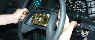
Before repairing the SAUO VAZ 2110 unit, you should make sure that the problems with the stove are associated with it. To do this, you should connect a known working heater control unit (borrow from a friend or from a store). If there are no problems with the stove with the working unit of the automatic control system, then we try to find out what the reason is. If the obviously working unit of the automatic control system did not help, then the problem with the stove lies elsewhere.
Remove the buttons next to the SAUO block. We take out the stove control unit. Set the controls to position 0 and remove, and then remove the front cover and glass from the latches. We unscrew 2 screws in the front and 1 in the back. Remove the board from the plastic case and check the integrity of all tracks, jumpers and resistors. In this example, a broken jumper was found. Solder it on one side and the other. Assembly in reverse order. Now all speeds of the SAUO block work.
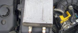
Heater radiator
| The heater radiator is connected by hoses to the engine cooling system. Coolant constantly circulates through the heater radiator. The heater control damper directs outside air to or bypass the heater core. In intermediate positions of the damper, part of the air passes through the radiator, and the rest bypasses the radiator. In the extreme positions of the damper, all air passes through the radiator or bypasses it. |
Fuse
A fuse is an electrical switching device designed to protect electrical circuits by breaking the circuit due to its destruction or shutting down when a current flowing through it exceeds the permissible values.
Fuses come in several types and are used in all electrical circuits to protect vehicles from short circuits (short circuits). They are classified according to the rated current of the fuse link.
The fuse link is the part of the fuse that is destroyed by electrical current.
The rated current is the current of the fuse at which the fuse-link will operate indefinitely and will not be subject to destruction.
Operating principle of the fuse
When using a fuse in an electrical circuit, the operating current passing through the fuse does not exceed its rated current - this is its normal operation. But as soon as a current appears in the electrical circuit that exceeds the safe permissible values in this circuit, regulated by the fuse, the fuse-link, under the influence of a current exceeding the rated current of the insert, begins to melt and collapse as a result of which the electrical circuit breaks.
You can restore the electrical circuit by replacing the fuse, but only after the culprit for the increased current in this electrical circuit has been found. Otherwise, the new fuse will also blow.
Heater assembly
1 — micromotor-reducer of the heater damper; 2 — heater control damper; 3 — additional heater fan resistor; 4 — blowing hose for the fan motor; 5 — heater fan; 6 — filter cover of the heating and ventilation system
The heater is installed in the engine compartment under the right windshield trim and is attached to the front panel. A filter is installed at the heater inlet to clean the air entering the heating and ventilation system.
Description of design
Heater parts : 1 — filter cover; 2 — heating and ventilation system filter; 3 — heater housing; 4 — micromotor-reducer of the heater damper; 5 — heater radiator; 6 — additional heater fan resistor; 7 - heater fan
The car is equipped with a heating and ventilation system, which serves to create the most comfortable conditions for the driver and passengers, regardless of weather conditions. The heating and ventilation system includes: heater, heater fan, cabin air temperature sensor, air distributor housing, air ducts and deflectors. The air from the heater enters the air distributor housing and then into the air ducts. Through them, air is supplied to the windshield and side window vents, to the central and side deflectors on the instrument panel, as well as to the feet of the driver and passengers. Air heaters of various types, configurations and purposes for any car can be selected on the website https://starter.ms/otopiteli.
Heating and ventilation control unit
The system is controlled by turning the handles located on the heating and ventilation control unit. The control unit is installed on the instrument panel console.
Interior temperature sensor
To maintain a given air temperature in the car interior at a constant level, there is a cabin air temperature sensor installed in the headliner trim.
Heater assembly : 1 — micromotor-reducer of the heater damper; 2 — heater control damper; 3 — additional heater fan resistor; 4 — blowing hose for the fan motor; 5 — heater fan; 6 — filter cover of the heating and ventilation system
The heater is installed in the engine compartment under the right windshield trim and is attached to the front panel. A filter is installed at the heater inlet to clean the air entering the heating and ventilation system.
Additional resistor
The heater housing contains a heater fan, a heater radiator, a heating and ventilation system filter, an additional fan resistor and a heater control damper connected to the temperature regulator. The heater radiator is connected by hoses to the engine cooling system. Coolant constantly circulates through the heater radiator. The heater control damper directs outside air to or bypass the heater core. In intermediate positions of the damper, part of the air passes through the radiator, and the rest bypasses the radiator. In the extreme positions of the damper, all air passes through the radiator or bypasses it.
Heater damper micromotor-reducer : 1 - micromotor-reducer; 2 — damper position sensor; 3 - output shaft
The heater control damper is turned by a micromotor-gearbox mounted on the left side of the heater body. The output shaft of the micromotor-gearbox is connected to the damper axis.
Location of the air distributor housing and air ducts on the instrument panel : 1 - side deflector air duct; 2 — air duct for blowing glass; 3 — air distributor housing; 4 - damper; 5 — damper gear motor; 6 - air duct for blowing the feet of the driver and passengers
The air distributor housing and air ducts are fixed on the reverse side of the instrument panel. The air distributor housing contains air flow control flaps, which are controlled by the air flow distribution regulator. The dampers are turned by a gear motor mounted on the air distributor housing. By controlling the flaps, the regulator directs air flows through the air ducts to the central and side deflectors, to the feet of the driver and passengers, as well as to the nozzles located in the instrument panel for blowing the windshield and front door windows. When the car moves, air is forced into the passenger compartment at high speed through the holes in the right facing of the wind window. To increase the air supply to the cabin while the car is moving, as well as when parked, a heater fan is used. The intensity of air supply is determined by the fan rotation speed. The fan motor can rotate at four speeds, depending on the connection of an additional resistor.
Electromagnetic relay
An electromagnetic relay is a switching device designed to relieve contacts. The work is based on the law of electromagnetic induction.
In cars, relays are used to unload contacts on control buttons, so that they, in turn, do not melt or heat up when more current appears on them. The relay consists of moving and non-moving contacts, a DC coil, a return spring, a coil core and an armature.
Relay operating principle
When a current appears on the relay coil, a magnetic field is formed in it, which in turn begins to attract the armature to which the movable contacts of the relay are attached. As a result, the moving contacts close with the fixed ones and the electrical circuit is completed.