This is the third pillar of the Republic of Kazakhstan
A transfer case (transfer case) is installed on all vehicles with all-wheel drive, which includes the Niva. On an all-wheel drive car, this element increases torque when moving in difficult conditions and distributes torque between the axles (drive axles). The box can also be installed on truck cranes, firefighting vehicles, where it is involved in operations with the drive of water pumps, pumps, etc.
The transfer case design differs on different machines, but there are common design features, including the presence of such parts as the drive shafts of the front and rear axles, drive shaft, oil sump, chain drive and center differential, crankcase, differential lock, and reduction gear.
Transfer case location and functions
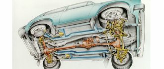
Location of the transfer case in the Niva 21213
The transfer case occupies an intermediate position in the vehicle transmission between the gearbox and the driveshaft. It has its own body in which its components are located.
The transfer case helps to implement such SUV capabilities as:
- Center differential lock.
- Disabling the drive axle.
- Increased torque of the drive wheels.
- Distribution of torque along the wheel axles.
Processes during engine operation
And now a little more about how all these processes occur in an internal combustion engine. Elementary physics largely influences the work here. For example, when you press the accelerator pedal, the valve in the throttle assembly sharply opens. The more it opens, the more air begins to be sucked into the fuel supply system.
Consequently, when you press the gas pedal, the load increases, and when you release it, the load decreases. We can say that the DMRV monitors these changes. It is worth noting that the main symptom of a malfunction of the mass air flow sensor is a decrease in the dynamic properties of the car.
Transfer case Niva 21213
Model VAZ-21213 is an all-terrain passenger car with permanent all-wheel drive and differential lock. Brand 21213 is a restyled version of the first VAZ SUV, VAZ-2121. RK Niva 21213 has three gears:
- the first - with a gear ratio of 1.2;
- the second, lowered – with the number 2.135;
- neutral
21213 is equipped with 4-speed and 5-speed gearboxes, and when the first speed of the transfer case is turned on, the car operates in standard mode, the gear ratios in the transmission are from 5-speed. The checkpoints are as follows:
- 1 – 4,4;
- 2 – 2,52;
- 3 – 1,63;
- 4 – 1,2;
- 5 – 0,98.
When you turn on the second position of the transfer case lever (reverse position), the gear ratios change (lower):
- 1 – 7,83;
- 2 –4,48;
- 3 – 2,90;
- 4 – 2,14;
- 5 – 1,75.
On ordinary roads, the transfer case is always in first gear, the transfer case control lever (reduction gear) is pushed forward. The neutral gear of the RK disconnects the transmission, and in this position the car does not drive; there is also a neutral in the gearbox.
Motorists often ask the question: why is neutral gear needed in a transfer case? The neutral is used when connecting additional units to the transmission, for example, a mechanical winch; in this case, a power take-off must also be installed.
Replacing the air flow sensor
To replace the sensor with your own hands, you need to prepare a shaped screwdriver and a “10” key.
The replacement procedure consists of the following steps:
- First you need to turn off the ignition and open the hood.
- Then you need to disconnect the negative terminal on the battery.
- At the next stage, you need to loosen the clamp with which the corrugation is attached to the mass air flow sensor.
- Next, remove the corrugation from the pipe.
- Then you need to bend the comb and disconnect the sensor connector.
Disconnecting the sensor connector
Then, using a “10” key, you need to unscrew the sensor mounting bolts to the air filter housing. Now you can remove the mass air flow sensor. Installing the sensor yourself is carried out in the reverse order.
Thus, if the car stalls and has all the signs of a breakdown of the mass air flow sensor, then before you start repairing it, you should check the level of its signal, it should not be low, perform a full diagnosis of the car and repair all faulty components and parts.
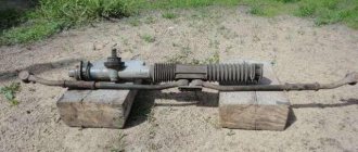
The device of the VAZ Niva transfer case
The transfer case is not present in all VAZ passenger cars, but only on cars with two drive axles. In the transmission, the transfer case (TC) is installed at the rear of the gearbox; a rear driveshaft is attached to its shank, which connects the transfer case to the rear axle. The front axle is also driven by the steering wheel; it is connected to the transfer case by a front driveshaft.
The reduction gear in the Republic of Kazakhstan is designed to obtain high torque, it is used to overcome difficult sections of the road, and helps to cope with off-road conditions. The VAZ Niva transfer case contains the following main parts:
- the body itself;
- front axle drive shaft;
- intermediate shaft;
- drive shaft;
- gears;
- bearings;
- differential housing;
- satellites;
- differential lock clutch;
- gear shift clutch;
- flanges (for connection to cardan shafts);
- oil seals;
- control levers.
Signs and causes of malfunction of the Niva Chevrolet flow meter
Since the controller responsible for recording OBD-II errors on the Chevy Niva lights up the “Check Engine” lamp only after the complete “death” of the patient, it is better to know the symptoms of the malfunction yourself.
- on an unheated engine, idle speed floats randomly;
- when you press the accelerator all the way and suddenly release the gas, the rpm hangs at 1500;
- starting a cold engine is difficult;
- under load the car may stall;
- When moving evenly, the engine jerks.
Why does the air flow sensor fail?
Natural demise does not occur quickly; under normal operating conditions, mass air flow sensors (especially BOSCH ones made in Germany) live and live for several years.
The quality of gasoline or the use of LPG does not affect them. All reasons are subjective, and are associated with the owner’s reluctance to invest in maintaining his car.
- Problems with the air filter. It is this that is the source of contaminants that kill the sensitive elements of the flow meter. This item includes untimely replacement of the filter, crooked installation (presence of cracks), loose fit of the mass flow sensor to the flange of the filter housing. Separate items include zero-resistance filters and incorrectly installed snorkels (typical for ShNiva).
- Water entering the air filter (after fording). The amount of liquid is not enough for water hammer, but droplets penetrate the air flow sensor and destroy the sensors.
- Oil in the intake manifold. We are not talking about the USR (it simply isn’t there), if there are problems with the crankcase ventilation valve, oil dust easily penetrates into the air duct, right up to the air filter.
As a result, the flow meter looks something like this:
At best, it will not work correctly, at worst, it will quickly fail.
All these points can be forgotten if you check the car components in a timely manner during maintenance.
Centering method
To carry out this work you will need a lift, although with some skill you can get by with simple supports. First you need to prepare the car. If there is a lift, it is raised up. If supports are used, the corners of the machine are jacked up one by one and it is placed on them. Please note that all supports must be stable, otherwise the work will be unsafe. You should also prepare the tool in advance. If there are no plans to simultaneously replace other parts, then it is quite possible to get by with a ratchet and a “13” head. During operation, an assistant must be in the cabin.
Adjustments are made in the following order:
- To begin with, you should evaluate the condition of the splines on the cardans. If they are very worn, then most likely you will not be able to perform the alignment correctly. In case of significant wear, parts should be replaced;
- The transfer case mount is inspected. Often the displacement can be seen with the naked eye;
- Next, loosen the transfer case mount. Just don’t unscrew it completely;
- After this, start the engine and “accelerate” the car to a speed of 80-90 km/h. In this case, the transfer case will fall into place on its own;
- The crucial point is to consolidate the result obtained. This can be achieved in 2 ways. Mechanics argue which one is better, but both are used in everyday life. Most often, the engine is turned off, and with its help the transfer case and cardan shafts are stopped.
- All that remains is to quickly tighten the nuts. Disadvantage here 2. Stopping the box in this way can have a negative impact on its condition.
- Also, you need to tighten the fastener as quickly as possible, otherwise it will be of no use. A more reliable, but technically complex method is to tighten with the engine running;
- The car is lowered to the ground and testing is performed.
If the vibration persists, the procedure should be repeated.
Throttle position sensor - TPS.
The function of this sensor is to provide information to the brain about the position of the gas pedal and the degree of throttle opening. The TPS contains electromechanical parts, that is, a potentiometer. This means that after some time it wears out and the sensor dies. In Russia there are about 10 companies producing this sensor
But I want to draw the reader’s attention to the so-called non-contact (inductive) TPS. It is made by one company that used to be a “mailbox”
My experience has shown that the sensor in their “non-contact” design is virtually eternal. This is exactly what is shown in the photo.
Eliminating prerequisites
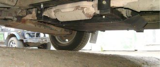
The misalignment of the transfer case occurs due to an undeveloped design. Therefore, many craftsmen strive to modify the fastening so as not to bother with alignment once a year. A special frame is used for this. In recent years, it can be purchased in stores, but you can also make it yourself. The advantages of this modification are the following:
- The transfer case is mounted on the rigid base of the subframe. The attachment to the body is made through a subframe, this allows to reduce the level of vibration transmitted to the body;
- It plays the role of a kind of protection for the crankcase;
- Also worth mentioning is adding additional rigidity to the side members.
- Among the disadvantages, we can mention a slight decrease in clearance. Although, in light of the advantages, this does not play a special role.
To assemble the subframe you will need a square pipe. Some people use a corner, but in this case the structure will be less durable. The support plates are made of sheet steel. Before assembly, you should cut off the old transfer case mounting bolts. Now it will be installed on the subframe. The pipe is cut to size and the frame is welded. After that, holes are drilled in the crossbars for fastening the transfer case. It is important not to make a mistake with the sizes. The next step will be assembling the mount to the body. Sheet steel support plates are welded to the subframe. Holes are drilled in it. After fitting, you need to drill holes in the floor of the car.
M12 bolts should be used for fastening
, as well as thick washers.
After installing the subframe, do not forget to treat it with an anti-corrosion compound. This will increase the service life of the part. This is how, through simple manipulations, you can get rid of one of Niva’s sores. Conclusion
. Even great cars have flaws. The domestic SUV Niva is no exception. During active use, vibrations emanating from the transmission may occur. That’s when the question arises of how to center the transfer case on the Niva. In fact, this work is not difficult, but there are some nuances that are better to know before starting work. Some people, knowing this feature of this car, install a subframe, this can significantly reduce the noise of the transmission.
Chevrolet Niva Light All-terrain Vehicle) › Logbook › Replaced transfer case cushions and rear driveshaft)
Nothing unusual, just replaced tired transfer case cushions. They waited for their time for a couple of months and now it has come) Recently, vibrations on the transfer case lever have been much greater than usual. As the replacement showed, it also replaced the rear cardan with a new one, because the lower crosspiece got tired and began to play a little. As it turned out, the grease nipple or grease fitting was lost from the crosspiece, with all the leakage, grease and dirt. I'll go over it at my leisure)
As for replacing the cushions itself, everything is simple, the main thing is to clean the nuts and studs, and moisten them with a bucket in advance, or with kerosene, vinegar, or in general, whatever seasoning you like) wait a little and you can turn it. We remove the pillow and the transfer case traverse on one side, replace it with new pillows, and put it back. Then on the other side.
Yes, I finally tightened the nuts after a little “centering” in fifth gear with the rear wheels hanging, they did it like that on old fields)
I also redid the silent in the front shock absorber, which I installed in the previous entry, removed it, it became loose in the ear, pressed the upper one from the classics, grinding off the ribs, and drove a machined bushing inside from the removed Shniv shock absorber silent. Now it doesn’t wobble, on the left, on the right I didn’t have time) In the process I “invented” the method of turning the bushing
As a result, the vibration on the transfer case lever has decreased relative to the previous level.
All. Bye everyone and good luck)
Niva transfer case. Ways to eliminate vibration
The Niva family of cars differs from VAZ passenger cars in permanent all-wheel drive - they have two drive axles. In total, the VAZ SUV has three differentials in its transmission - one for each axle and another center differential.
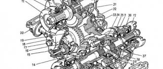
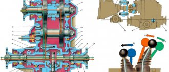
1. Oil seal; 2. Thrust ring of the front bearing of the drive shaft; 3. Front bearing cover; 4. Front drive shaft bearing; 5. Transfer case front cover; 6. High gear; 7. Gear clutch hub; 8. Gear clutch; 9. Low gear; 10. Transfer case housing; 11. Rear drive shaft bearing; 12. Drive shaft; 13. Transfer case rear cover; 14. Intermediate shaft; 15. Rear intermediate shaft bearing; 16. Rear differential housing bearing; 17. Installation ring of the rear axle drive shaft bearing; 18. Rear axle drive shaft bearing; 19. Oil seal deflector; 20. Rear axle drive shaft flange; 21. Rear axle drive shaft; 22. Bearing thrust ring; 23. Differential housing; 24. Rear axle drive gear; 25. Satellite; 26. Axle of satellites; 27. Retaining ring of the satellite axis; 28. Spring washer; 29. Driven gear; 30. Differential housing bearing retaining ring; 31. Differential locking clutch; 32. Front axle drive shaft; 33. Front axle drive housing; 34. Retaining ring of the front axle drive shaft bearing; 35. Differential bearing spring washer; 36. Front differential housing bearing; 37. Driven gear of the speedometer drive; 38. Speedometer drive housing; 39. Front intermediate shaft bearing; 40. Gearbox; 41. Elastic coupling; 42. Constant velocity joint; 43. Transfer case; 44. Shims; 45. Transfer case suspension bracket; 46. Rear engine mount bracket.
Operating principle
Modern Nivas use BOSCH sensors 0 258 006 537; NTK:629-W2:8965 and others. These are zirconium elements that react to the volumetric amount of oxygen in the exhaust and produce an output voltage in the range: 0.1–0.9 V (high O2 content - low O2 content).
The operation of the device is based on the principle of comparing the amount of oxygen in the exhaust gases and in atmospheric air sealed in the internal chamber of the lambda probe. It has 2 platinum electrodes separated by zirconium dioxide, which are surrounded by different oxygen environments. The device starts working only when heated to 300 °C and above. When heated, zirconium acquires the properties of an electrolyte and a potential difference arises between the electrodes.
Therefore, during ignition, until the engine warms up and the oxygen sensor starts working, the fuel supply to the injectors is adjusted according to a cycle programmed in the ECU controller.
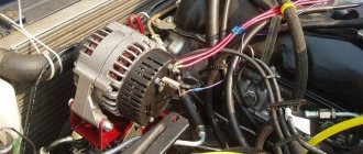
Eliminate vibration with additional fasteners
Installing the third support of the transfer case on VAZ 21213/21214 vehicles allows you to reduce the level of vibration of the transfer case; with this support it is easier to center the transfer case. The part can be purchased at auto stores or made yourself. The finished product comes with three long studs (for model 2121); to install the third support on this machine, you will need to unscrew the short studs from the transfer case housing and install new studs from the kit. We carry out repairs as follows:
- dismantle the front passenger seat in the cabin;
- remove the floor tunnel lining;
- in the cabin we move aside the carpet covering the body amplifier (in front of the handbrake lever);
- remove the transfer case (alternatively, you can simply hang it up, but removing the third support makes it easier to install);
- We attach the bracket of the new support to the body of the RC;
- we install the transfer case in place, center it in the optimal position, and fasten the side supports;
- we combine the third support with the body, drill two holes in the bottom;
- Using washers, bolts and nuts (from the kit) we attach the support to the bottom of the body.
Vibration is eliminated more effectively by installing a subframe under the transfer case. You can also make such a device yourself or buy a finished product at a car store.
In order to install the subframe, the transfer case must be removed. It is more convenient to carry out such work in a pit; we carry out repairs as follows:
- leave the car in neutral gear;
- disconnect the propeller shaft from the transfer case, it is advisable to mark the driveshaft flange and the drive shaft so that during installation, align the driveshaft according to the marks - this way, the occurrence of unnecessary vibrations is eliminated;
- dismantle the muffler mounting bracket;
- remove the gearbox traverse;
- jack up the transfer case, remove the side fastenings of the transfer case;
- We treat the places where the subframe fits to the body with Movil;
- place the subframe on the gearbox studs;
- we mark the attachment points of the subframe on the side members, drill holes, attach bolts to the body;
- we tighten all fastenings, except for the transfer case supports themselves;
- we perform alignment of the steering wheel;
- Finally tighten the transfer case supports.
It should be noted that installing an additional support or subframe on the steering wheel does not always lead to the desired effect; in some cases, vibration only increases.
Lada 4×4 3D Adventure time ⌚ › Logbook › Installation of a vibration damper and the third support of the vehicle
After installing the transfer case supports of the new model, incomprehensible knocking noises appeared, which seemed to have gotten rid of, but they came out again.
I assumed that due to the “softer” supports, the transfer case sways more and this causes shocks in the transmission. This did not happen with the old supports. Reading the next entry in the BZ on the drive, I saw that a person had installed a subframe and was giving away for a nominal fee (500 rubles) a traverse with a vibration damper and a third support of the RK. I bought it for an experiment, although delivery cost the same 500 rubles. But in general, it is several times cheaper than buying the same spare parts new in a store. =)
The vibration damper was slightly bent, or rather its mounting. I straightened everything out, assembled it, and installed the traverse. There were no problems.
I also installed the third support. I had to tinker a little, of course. I didn’t remove the plastic cover of the tunnel, although I removed the driver’s seat for ease of work. I bent the casing up a little and installed the bolts, and to prevent them from turning, I made a fixing frame.
After installing the third support, I did not center the transfer case, I set it up quickly. The vibration that was previously at 1800 rpm has shifted to approximately 2200-2300 rpm. That's okay, we need to set the transfer case to normal.
Now the transfer case should no longer nod, but, nevertheless, the shocks when changing gears remain. And everything gives off somewhere in the area of the right foot, under the heel. I started to figure it out. It turned out that there was a large gap in the flange in the rear cover of the control valve. Those. If you move the cardan up and down with your hand, you hear a good knock. If this is the reason, then how is the knocking transmitted to the legs? I don't understand. There is some play in the flange of the front cover of the RC, but not much, there is no knocking. But at the same time, the cardan rotates relative to the axis at a large angle.
Did the transfer case “nod” more strongly on the softer cushion and the bearings were broken? Let me remind you that the cardans are CV joints and there seem to be no problems.
In any case, it will be necessary to change the bearings in the transfer case covers, or better yet, change the covers to new ones with double-row bearings. But there are no funds for this yet. In the garage there is a second transfer case, removed from the same car, which was very noisy. You can try to sort it out, replace the covers and bearings. I’ve never done this myself, but I think I can do anything.
I'm going like this for now. If you try to release the clutch more smoothly and choose the right moment, then there are no shocks.
I did not check the operation of the vibration damper. You need to center the transfer case, remove vibrations from it, and only then check the car on the track.
Source
We study problems and repair methods.
Any car owner definitely doesn’t need to be told why howling and humming are bad. Vibration of the transfer case on a Niva at low speed is quite common. The driver, of course, gradually gets used to many extraneous sounds in the car, but the noise level is high enough to make it impossible to carry on a conversation with passengers while traveling. Due to excessive noise pollution, you will inevitably have to deal with the problem.
Sources
- https://motorltd.ru/snyatie-i-tsentrirovanie-razdatochnoy-korobki-vaz/
- https://www.vazzz.ru/vaz-21213-razdatka-ustrojstvo-shema-tsentrovka-snyatie/
- https://avto-idea.ru/remont/remont-razdatki-na-nive-21213-kak-ottsentrovat/
- https://AutoFlit.ru/2260-kak-otcentrovat-razdatku-na-nive-sposob-dlya-korotysha-i-shevrole.html
- https://NewNiva.ru/kak-ustranit-vibratsiyu-na-nive-21214.html
[collapse]
Diagnostics of mass air flow sensor
In principle, the mass air flow sensor is not as critical for starting the engine as, for example, the DPKV. It can be turned off by pulling out the connector, the ECU will go into emergency mode and will determine portions of air in the fuel mixture using another sensor - the TPS throttle position.
Therefore, the breakdown is determined in several stages according to the degree of complexity:
- visual inspection and disconnection of the sensor;
- determining the compliance of a specific modification of the mass flow sensor with the ECU firmware;
- diagnostics with a tester in voltmeter mode.
This will reduce the complexity of the process. For example, before checking the mass air flow sensor with a tester, you should make sure that the sensor is compatible with a specific MIKAS controller and that the original brains have not been flashed.
Checking the serviceability of the mass air flow sensor using a multimeterChecking the serviceability of the mass air flow sensor using a multimeter
Visual inspection
The mass air flow sensor is checked after access to this sensor is provided. To do this, you will need to partially dismantle the air intake elements (usually the corrugation). Knowing how a VU meter works, you can visually detect mechanical damage or traces of liquids/dirt in the pipe.
Rice. 11 Inspection of the air sensor and corrugation
Oil gets inside the corrugation due to a clogged oil sump of the crankcase ventilation system or when the lubricant level inside it increases. If the machine's maintenance schedule is violated, dust and dirt get onto the walls of the pipe, as the air filter becomes clogged.
After removing the sensor from the air filter housing, the inlet mesh should be clean. If there is a build-up of dust, most likely the rubber seal was not installed tightly and unfiltered air was getting inside. In any of these cases, the operation of the mass air flow sensor is disrupted by default.
Diagnostics on the move
The following method for checking the air sensor allows you to determine its performance. You don’t need a tester or other tools for this:
- Diagnostics of the mass air flow sensor is carried out after disconnecting the ECU connector;
- the engine starts, Check lights up on the panel, indicating a sensor malfunction;
- however, the controller goes into emergency mode, ensuring the operation of the internal combustion engine;
- If the dynamic characteristics of the engine improve when driving with the air sensor turned off, then the mass air flow sensor is faulty.
Rice. 12 Disabling the mass air flow sensor
Compliance of the mass flow sensor with the ECU firmware
As necessary, owners reflash the computer's brains to improve performance, while getting side problems. For example, if the MIKAS controller has been updated with firmware, the mass air flow sensor may not work correctly.
In this case, it is fundamentally incorrect to talk about a sensor malfunction, but its signals are not intended for the new version of the MIKAS controller that was installed on it. In this case, the only way to identify signs of a malfunction in the mass air flow sensor is:
- change the angle of the throttle valve (usually a 1 mm shim near the throttle stop);
- disconnect the mass air flow sensor while the engine is running (pull the chip out of the connector).
Design Features
This is one of the most expensive sensors in the internal combustion engine control system. The reason for this is that it contains an expensive metal, namely platinum. The basis of the sensor is a plastic tube of a strictly defined diameter. It is located between the filter and the throttle assembly. Inside the case there is a thin wire made of platinum. Its diameter is about 70 micrometers.
Of course, it is very difficult to measure the passing air. In an internal combustion engine control system, air flow measurement is based on temperature measurement. The platinum wire is subjected to sudden heating. By how much its temperature drops in comparison with the set one, the amount of air passing through the sensor body is determined. Pay attention to the sign of a bad mass air flow sensor to know if it is OK.