Transfer case Niva 21213
The transfer case is not present in all VAZ passenger cars, but only on cars with two drive axles.
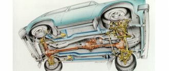
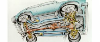
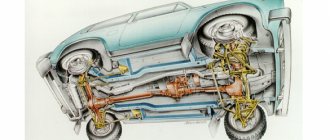
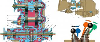
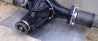
In the transmission, the transfer case (TC) is installed at the rear of the gearbox; a rear driveshaft is attached to its shank, which connects the transfer case to the rear axle. The front axle is also driven by the steering wheel; it is connected to the transfer case by a front driveshaft. The reduction gear in the Republic of Kazakhstan is designed to obtain high torque, it is used to overcome difficult sections of the road, and helps to cope with off-road conditions. The VAZ Niva transfer case contains the following main parts:
- the body itself;
- front axle drive shaft;
- intermediate shaft;
- drive shaft;
- gears;
- bearings;
- differential housing;
- satellites;
- differential lock clutch;
- gear shift clutch;
- flanges (for connection to cardan shafts);
- oil seals;
- control levers.
https://www.youtube.com/watch?v=ytadvertiseen-GB
Model VAZ-21213 is an all-terrain passenger car with permanent all-wheel drive and differential lock. Brand 21213 is a restyled version of the first VAZ SUV, VAZ-2121. RK Niva 21213 has three gears:
- the first - with a gear ratio of 1.2;
- the second, lowered – with the number 2.135;
- neutral
21213 is equipped with 4-speed and 5-speed gearboxes, and when the first speed of the transfer case is turned on, the car operates in standard mode, the gear ratios in the transmission are from 5-speed. The checkpoints are as follows:
- 1 – 4,4;
- 2 – 2,52;
- 3 – 1,63;
- 4 – 1,2;
- 5 – 0,98.
When you turn on the second position of the transfer case lever (reverse position), the gear ratios change (lower):
- 1 – 7,83;
- 2 –4,48;
- 3 – 2,90;
- 4 – 2,14;
- 5 – 1,75.
On ordinary roads, the transfer case is always in first gear, the transfer case control lever (reduction gear) is pushed forward. The neutral gear of the RK disconnects the transmission, and in this position the car does not drive; there is also a neutral in the gearbox.
Motorists often ask the question: why is neutral gear needed in a transfer case? The neutral is used when connecting additional units to the transmission, for example, a mechanical winch; in this case, a power take-off must also be installed.
The transfer case on the Niva is a fairly reliable unit; problems with repairs in the mechanism itself arise mainly due to insufficient oil level in the valve - if for some reason the oil leaks out, intensive wear of all parts occurs. Among the frequently occurring malfunctions are:
- vibration in the body at various speeds when the car is moving;
- vibration when the vehicle starts moving;
- noise in the transfer case when the car is slipping or turning;
- difficult upshift or downshift, difficult engagement of the lock.
| Centering the transfer case of VAZ-21213 Author ALER | GetPath(); Conference “Let's exchange experiences. Niva» NIVA-FAQ Equipment Transmission Transfer case |
The method of dynamic centering (balancing) of the VAZ-21213 transfer case is described here. The success of the operation (i.e., elimination of vibration and noise) depends not only on the transfer case itself, but also on the condition of the intermediate shaft and universal joints (and their crosspieces), since the complex of all of these components is balanced. It is recommended to carefully check and inject the splines and crosspieces of the universal joints. It also doesn't hurt to pre-balance the wheels.
Centering is performed by two people—let’s call the participants “driver” and “mechanic.” The car with the driver rises on a lift. Transfer case lever position: lock off, gear up. The gearbox engages fourth or fifth gear (see below about speed). The mechanic loosens the transfer case (4 nuts).
And the subtleties of the process are as follows.
1. The speed at which centering is performed may vary. One service recommended that I keep 60 km/h in fourth gear. This makes sense if the machine is used only in the city. In another - 90 km/h in fifth gear. I drive fast, so I prefer 100-110 km/h in fifth.
2. Loosening of the transfer case should be minimal, but sufficient for its mobility. The point of this subtlety is that the transfer case, when centered, is practically in the same horizontal plane as during operation.
3. Before centering, you need to place the transfer case supports so that the studs initially stand in the middle of the oval holes of the supports. This is possible due to the mobility of the splined joints of the cardan shafts. This installation provides maximum freedom for the transfer case to find the optimal position.
4. After gaining speed, the mechanic must push the transfer case several times from the side to the front, from the side to the back, or just from the side - to make it easier for it to find the optimum. But not forward or backward. This can be done, for example, with the handle of a hammer.
Advice - if centering is done at a service center in front of you, it is better not to get behind the wheel yourself, but to control the process from below, that is, to be, according to the role indicated at the beginning of the article, not a driver, but a mechanic or simply an “observer”.
Naturally, it is not at all necessary to have a lift. You can do this in a pit or just a flat area. The best result is obtained by exclusive centering - on stands under the suspension arms with the wheels removed. With this centering, the cardan shafts have the same angles as when the car is moving. Of course, the machine must be securely secured to avoid unnecessary risk. I know of a case where during centering they used stands made from stacks of bricks from which the car simply fell...
For the VAZ-2121, before dynamic centering, it is necessary to set the height of the transfer case by installing spacers under the transfer case supports. Gaskets are rectangular plates of different thicknesses. Their size corresponds to the dimensions of the transfer case supports, and instead of holes there are side cutouts so that the plates can be inserted under the supports without removing them from the studs. The use of washers instead of gaskets is strictly not recommended.
The method is well described in the Maintenance and Repair Manual. We can recommend the article in “Behind the Wheel”, which proposes an optical method (info provided by VadimM, TigerD and Vlad219i). At the end of the mentioned article there is a link to the article in ZR 1/98, where the method outlined in this article is briefly described, but in a more primitive form.
In the intermediate shaft of the VAZ-21213, a CV joint is used instead of a cardan, which allowed the plant to refuse to adjust the position of the transfer case in height. However, if there is noticeable deformation of the bottom in the area where the gearbox and/or transfer case is mounted, and also if the dynamic centering method does not give the desired result, you can try to adjust the position of the transfer case in height, and then repeat the dynamic centering.
I had to deal with another option for positioning the steering wheel - along the axis of the machine.
https://www.youtube.com/watch?v=upload
My 213 had the usual problem - the nut of the gearbox secondary shaft shank had come loose. I removed the boxes, went through the gearbox, then, when installing the boxes, I noticed that the studs on the CV joint of the drive shaft barely fit into the holes of the drive shaft flange when the gearbox was in the position closest to the gearbox. Everything came together due to the deformation of the elastic coupling.
I consulted with an authority on NIVAM in one service. He said approximately the following (he himself has a NIVA 2121): in his experience, the shaft with a CV joint is about 5 mm shorter than the shaft with a cardan joint, and the installation locations of the gearbox and gearbox on the 213th NIVA remained the same; axial stress during the assembly of the shaft and gearbox seems to be the cause of chronic problems with 5th gear and, in general, with the gearbox on many 213 NIVAHs.
Also interesting: Interior heater valve VAZ 2121 Niva 2131
1) elongated studs were installed on the shaft instead of the standard ones; 2) between the ends of the drive shaft and the flange of the primary shaft of the RK (on the studs of the drive shaft), an insert with a thickness of about 5 mm is mounted (the insert is simply made from the drive gear flange of the rear axle by cutting off the excess on a lathe from its end part, on which there are exactly the necessary holes).
As a result, the unit operates without unnecessary axial stress.
This is also done on my car. Now everything is assembled much easier, positioning the control unit is also easier (however, now it is necessary to remember when assembling that if the control unit is excessively shifted towards the gearbox, the blower shaft can seem to “sag” and give off its own vibrations).
vlavuk, 03.08.01.
I haven't encountered a similar problem. And on both my Nivkas, and on the cars of other Nivkas that I observed during centering, the transfer case, after its installation, stood up so that the studs ended up in the middle of the oval holes of the brackets. But this is not a reason to deny the situation described above.
Centering the Niva transfer case horizontally
Correct installation of the transfer case can be done in several ways. Most often in auto repair shops, repairmen use the following method:
- hang the car on a lift;
- loosen the transfer case;
- start the engine;
- engage the gear and accelerate the car according to the speedometer to the speed at which vibration occurs (often it occurs at speeds from 40 to 80 km/h);
- without using the brakes, reduce the engine speed, then turn off the ignition.
The transfer case itself is centered in place, all that remains is to tighten the fastenings of the supports.
https://www.youtube.com/watch?v=ytcreatorsen-GB
You can also adjust the position of the RC using a wire; we do it as follows:
- loosen all four fastenings of the transfer case supports;
- fasten one end of the wire to the rubber coupling of the propeller shaft;
- we attach another piece of wire to the CV joint, bring the other ends of the wire to each other;
- rotate the shaft; if the transfer case is not centered, the ends of the wire will diverge during rotation;
- the task comes down to installing the transfer case using the selection method so that the ends of the wire practically do not diverge from each other in any position when turning the shaft.
There is nothing fundamentally complicated in the design of the multiplier, except that it itself is not attached to the main gearbox as on more modern all-terrain vehicles. Intermediate driveshafts extend from the transfer case to the manual transmission. The rest of the device is represented by gears, satellites and bearings. The design also includes a free differential with locking.
Main problems with the range multiplier
The main function of the range multiplier has the properties of a gearbox divider; it turns them on or off the gear speed.
Most transfer case breakdowns are purely mechanical in nature (for example, a cut shaft between the gearbox and the transfer case). This is provoked by inattention to fuel and lubricant levels, wear of rubber bands, incorrect location (alignment) of the unit, and the condition of adjacent components. The first indicator of problems with the transfer case is characteristic noise and vibration in the body.
Vibration when driving on Niva
The first reason is that at a speed of more than 70 km per hour, it’s all about the cardan shaft; only the original one must be installed. Next, replace the crosspiece on the cardan shaft, after which you must drag the shaft to a stand and balance it, otherwise the vibration will resume.
The second reason for vibration is the intermediate shaft, it must also be original, otherwise it will quickly fail. We take only the original AvtoVAZ one from the factory, otherwise vibration and breakdowns cannot be avoided.
The third reason for vibration is the breakdown of the gearbox flange bearings. To eliminate the problem, place additional support on the gearbox.
How to overcome noise when maneuvering in a transfer case
You can buy new handles for the levers. We change it ourselves, prying up the support with a screwdriver, take out the lever axis and get rid of the old handles. We remove the old lever springs and install new ones. Insert the lever axis and secure it with a corkscrew nut. Now, when driving with the new handles, there is no characteristic noise in the cabin. The handles can be easily changed without leaving the salon.
Stiff switching of the lock lever
This issue can be easily solved in the following way: when driving, just turn the steering wheel slightly and the lock will immediately turn on without any problems.
There are also: jamming of the pneumatic cylinder, sticking in the neutral position, or the rod is sitting tightly. Burnt gear and shift fork.
Transfer case for Niva, signs of breakdowns:
- problematic engagement of the front axle;
- overheating of the range multiplier;
- leakage or excessive consumption of oil during operation of the transfer case;
- self-switching of the front axle.
Repairing the transfer case in Niva 21213 with your own hands is quite possible in case of minor breakdowns. The owner of a Chevy Niva will only need the basic skills of a car mechanic. It is more difficult to correctly install and center the Niva transfer case. Here it is still recommended to contact a car service. A diagram of the unit itself is presented in the vehicle documentation.
Niva transmission how to operate correctly: operating principle
The VAZ 2121, in other words, “Niva”, entered mass production in the 70s of the last century. This car belongs to the class of off-road passenger cars. In the history of the domestic automobile industry, Niva became the first car whose design used all-wheel drive. Let's take a closer look at the transmission device.
The transmission in the Niva family (2121, 2131) is designed in such a way that all-wheel drive is supplied to 4 wheels. Also characteristic is the presence of a center differential. The transmission includes a gearbox, a transfer mechanism, a pair of cardan shafts, and both axles. A characteristic feature of the 2131 model is its elongated body.
Then it goes through the cardan shafts to the gearboxes. The front gearbox transmits torque to the wheels through the differential and constant velocity joints. Likewise for the rear, also protruding, driving wheels. It is precisely because the torque is distributed to 4 wheels simultaneously that the drive is called full drive. The designation is as follows – 4WD. Another domestic car, designed on a similar principle to the Niva, is the UAZ.
Installation
For ease of installation, the car is fixed on a lift or above a pit. Pre-preservation of surfaces (attachment points, subframe) is carried out using protective agents, for example, Movil.
The finished product is tried on site individually for each vehicle. 4 holes are drilled along the perimeter of the structure, symmetrical relative to the center line. Having previously loosened the transfer case fasteners.
Having placed the plates on the interior side, as in the photo, the subframe is attached to the side members with M12x1.25 bolts.
The RK brackets are sequentially removed, turned over and freely fixed to the subframe. The position of the shaft flanges is adjusted until minimal gaps are formed by moving the entire structure. Alignment is performed at 3000 rpm with the machine standing.
The bolts are thoroughly tightened.
The device of the VAZ Niva transfer case
The relatively complex scheme for distributing torque from the internal combustion engine to the wheels is explained by the universal purpose of the Niva 2121 - if used correctly, it can be used comfortably in the city and along muddy country roads. Such properties are ensured by the presence of a transfer case with a center differential lock, complementing a 4- or 5-speed manual transmission, depending on the year of manufacture.
TRANSFER CASE SHIFTING
Transfer case levers and their positions
H - low gear;
N - neutral position;
B - top gear.
P - differential unlocked;
https://www.youtube.com/watch?v=ytpressen-GB
B - differential is locked. When the lever is moved to this position, a warning light comes on in the instrument cluster, warning that the differential is locked.
NOTE Shifting from low to high gears and locking the differential can be done while driving with the clutch disengaged.
It is recommended to engage low gear in the transfer case after the vehicle has come to a complete stop and with the engine disconnected from the transmission.
To overcome difficult sections of the road, block the differential in advance. Do not lock the differential when the car's wheels are slipping. After overcoming such sections, unlock the differential - driving the car on good roads with a locked differential shortens the life of the power transmission mechanisms, increases tire wear and fuel consumption, and when braking the car can lead to skidding.
SHIFTING TRANSMISSION GEARS
Gear shift diagram (also printed on the handle)
Before driving, check the position of the transfer case levers - it must correspond to the road conditions. Start driving in first gear and, as the crankshaft speed increases, move to higher gears in a timely manner.
In time and in accordance with the road situation, change to a lower gear in the gearbox, avoiding overloading the engine.
To move in reverse, press the gear shift lever, pushing it all the way down and move it to the position corresponding to engaging reverse gear. Engage reverse gear only when the car is completely stopped.
In 1994, an updated version of the SUV was released, labeled Niva 21213, differing from the previous version in a more powerful power unit. Since 2006, this series of cars has been known as Niva 4x4.
The VAZ Niva series was developed as a universal all-terrain vehicle. These cars perform well in both off-road and city roads. One of the components that ensure high cross-country ability is a high-quality multiplier (distributor).
The Selectable 4WD drive is a hybrid of the modes discussed; it has the ability to enable Part-time and Full-Time. It is quite complex in design and management.
It has the most operating modes:
- 2WD or 2H (single axle drive);
- 4 part time or 4H (all-wheel drive with differential lock);
- 4 full time or 4HLc (permanent all-wheel drive with automatic gear ratio distribution);
- N (neutral);
- 4Lo or 4LLc (low range with differential lock).
The normal position for the RK handles, ensuring adequate behavior on the road of good quality:
- Front - from yourself
- Rear - towards you
Photo No. 3
The special operating mode of the transmission is switched on not long before the car begins to overcome an obstacle (rut, mud, ford or rise). The transition to the lowest row must be done while stopping. Returning to top gear is allowed on the go, although it causes problems for beginners due to the lack of the usual synchronizer.
It is somewhat more difficult to properly handle the forced manual locking of the center differential. On the contrary, it turns on when the car moves slightly (up to 20 km/h) due to misalignment of the grooves on the locking clutch, satellites and ring gear. To simplify turning the lever into the desired position, taking into account the Niva 2121 transfer case, pick up a small speed, then, shaking the steering wheel, pull the handle towards you.
Also interesting: Installing an alternator belt and air conditioner on a Chevrolet Niva
https://www.youtube.com/watch?v=ytabouten-GB
Photo No. 4
Problems can also arise when disengaging the lockout, as the clutch teeth literally catch on the ring gear. Engage reverse and, rocking the steering wheel, push the lever away from you. This action is performed immediately after overcoming a difficult section in order to avoid overloading the gearbox. It is most effective to disable the differential together with the transition to lower stages.
vlavuk, 03.08.01.
The purpose of the differential is to distribute engine power to two wheels, allowing them to move at different speeds. The average wheel speed is displayed on the panel. Thus, the differential is the device that makes an SUV an SUV.
If manufacturers decided not to include a differential in the transfer case structure, the result would be frequent tire wear. This would have been a blessing for tire manufacturers, but the developers turned out to be smarter. In addition, the differential reduces the load on the axle.
Materials, tools and drawings
The protection is mainly used for models 21214, 2121, 21213, which have vibration problems. To assemble a subframe on the field with your own hands for a transfer case, you will need metal channels, angles, bolts and a sheet of thin metal as the main materials. In addition to materials, you need to get diagrams or a drawing of the subframe. The simplest design consists of two transverse parts and two crossbars that connect them. Tools worth preparing:
- grinder;
- drill;
- measuring instruments - calipers, ruler;
- bank;
- hammer.
To protect against metal filings, you should take protective clothing made of thick fabric.
There are several design options, so the number of channels and angles may vary depending on the drawing.
Overcoming a deep puddle
How ESP Works in a CarOften, a dispute arises between motorists about how best to cross a ford with a transfer case. Some people prefer to “fly” into a puddle from acceleration, others prefer to downshift. If you get into a mud pit, there is a high risk of water hammer - water enters the cylinders through the filter, and the engine “chokes.”
To exclude this, many install a special snorkel. But you can do without it. A deep puddle should be overcome in second low gear. This is done so that in case of trouble (when the car starts to fail) you can switch to first gear in time and not stall. If you enter the water from acceleration (which is a better decision), remember that the wheels may get stuck in the middle of the journey. The engine power is not enough to turn the wheels - the car stalls, and the engine experiences a hydraulic shock.
Centering method
To carry out this work you will need a lift, although with some skill you can get by with simple supports. First you need to prepare the car. If there is a lift, it is raised up. If supports are used, the corners of the machine are jacked up one by one and it is placed on them. Please note that all supports must be stable, otherwise the work will be unsafe. You should also prepare the tool in advance. If there are no plans to simultaneously replace other parts, then it is quite possible to get by with a ratchet and a “13” head. During operation, an assistant must be in the cabin.
Eliminate vibration with additional fasteners
Vibration in the body is the main “disease” of the Niva; it often occurs due to improper alignment of the transfer case. Most often, vibration occurs on VAZ 21213/21214 cars, since the transfer case is mounted only on two supports on the sides of the body; on the Chevrolet Niva, the transfer case is already installed on three supports.
- driveshafts are poorly secured;
- wheels are not balanced;
- there is play in the cardan crosspieces (vibration is especially affected by play in the rear driveshaft crosspieces);
- The vibration comes from the engine itself.
Vibration when starting off on a Niva can also occur for the following reasons:
- the mounting supports of the transfer case have become loose;
- The rubber on the RK supports themselves broke.
Installing the third support of the transfer case on VAZ 21213/21214 vehicles allows you to reduce the level of vibration of the transfer case; with this support it is easier to center the transfer case. The part can be purchased at auto stores or made yourself. The finished product comes with three long studs (for model 2121); to install the third support on this machine, you will need to unscrew the short studs from the transfer case housing and install new studs from the kit. We carry out repairs as follows:
- dismantle the front passenger seat in the cabin;
- remove the floor tunnel lining;
- in the cabin we move aside the carpet covering the body amplifier (in front of the handbrake lever);
- remove the transfer case (alternatively, you can simply hang it up, but removing the third support makes it easier to install);
- We attach the bracket of the new support to the body of the RC;
- we install the transfer case in place, center it in the optimal position, and fasten the side supports;
- we combine the third support with the body, drill two holes in the bottom;
- Using washers, bolts and nuts (from the kit) we attach the support to the bottom of the body.
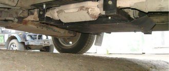
Vibration is eliminated more effectively by installing a subframe under the transfer case. You can also make such a device yourself or buy a finished product at a car store.
In order to install the subframe, the transfer case must be removed. It is more convenient to carry out such work in a pit; we carry out repairs as follows:
- leave the car in neutral gear;
- disconnect the propeller shaft from the transfer case, it is advisable to mark the driveshaft flange and the drive shaft so that during installation, align the driveshaft according to the marks - this way, the occurrence of unnecessary vibrations is eliminated;
- dismantle the muffler mounting bracket;
- remove the gearbox traverse;
- jack up the transfer case, remove the side fastenings of the transfer case;
- We treat the places where the subframe fits to the body with Movil;
- place the subframe on the gearbox studs;
- we mark the attachment points of the subframe on the side members, drill holes, attach bolts to the body;
- we tighten all fastenings, except for the transfer case supports themselves;
- we perform alignment of the steering wheel;
- Finally tighten the transfer case supports.
It should be noted that installing an additional support or subframe on the steering wheel does not always lead to the desired effect; in some cases, vibration only increases.
The misalignment of the transfer case occurs due to an undeveloped design. Therefore, many craftsmen strive to modify the fastening so as not to bother with alignment once a year. A special frame is used for this. In recent years, it can be purchased in stores, but you can also make it yourself.
The advantages of this modification are the following:
- The transfer case is mounted on the rigid base of the subframe. The attachment to the body is made through a subframe, this allows to reduce the level of vibration transmitted to the body;
- It plays the role of a kind of protection for the crankcase;
- Also worth mentioning is adding additional rigidity to the side members.
- Among the disadvantages, we can mention a slight decrease in clearance. Although, in light of the advantages, this does not play a special role.
To assemble the subframe you will need a square pipe. Some people use a corner, but in this case the structure will be less durable. The support plates are made of sheet steel.
Before assembly, you should cut off the old transfer case mounting bolts. Now it will be installed on the subframe. The pipe is cut to size and the frame is welded. After that, holes are drilled in the crossbars for fastening the transfer case.
It is important not to make a mistake with the sizes. The next step will be assembling the mount to the body
https://www.youtube.com/watch?v=ytcopyrighten-GB
Sheet steel support plates are welded to the subframe. Holes are drilled in it. After fitting, you need to drill holes in the floor of the car.
M12 bolts should be used for fastening
, as well as thick washers. After installing the subframe, do not forget to treat it with an anti-corrosion compound. This will increase the service life of the part. This is how, through simple manipulations, you can get rid of one of Niva’s sores.
Conclusion
. Even great cars have flaws. The domestic SUV Niva is no exception. During active use, vibrations emanating from the transmission may occur. That’s when the question arises of how to center the transfer case on the Niva. In fact, this work is not difficult, but there are some nuances that are better to know before starting work. Some people, knowing this feature of this car, install a subframe, this can significantly reduce the noise of the transmission.
Transfer case height alignment — Lada 4×4 3D, 1.7 l., 1995 on DRIVE2
Hello everyone! When I was patching the bottom, I cut off the transfer case mounting bolts, welded a thicker plate, drilled it through the old holes, inserted new bolts and grabbed them for welding. And what happened, what happened was that when I tightened the transfer case, the original floor sank in because... The new plate did not lie tightly. This means that you need to center it, and here’s how I did it. I screwed two pieces of wire onto the drive shaft, adjusted them so that the ends came together end-to-end when you lift them up, then twist the drive shaft and look, I got a gap of about 7 mm at the bottom. Since I didn’t find anything except thick paronite, I had to cut it. First I placed one plate at a time, and saw that the gap had become approximately half as large, then I placed another one at a time. Let's check... Now the wires don't diverge, at least I didn't notice it with my eyes! Now the transfer case is centered in height. Then I put the car on chocks, loosened the transfer case mounting nuts, accelerated it to 80 km/h using a choke and tightened the nuts. Let's hope that the vibration will become less!
All the best!
Disassembly
1 — front axle drive housing; 2 — crankcase cover; 3 — speedometer drive housing fig. 3-39fig. 3-38
rice. 3-38fig. 3-39
1- intermediate shaft; 2 - drive shaft; 3 — differential; 4 - front cover
1 - flange; 2 — oil seal; 3 — thrust ring of the bearing, 4 — front bearing; 5 - drive shaft; 6—high gear; 7 — hub; 8 - coupling; 9 — low gear; 10 — bushing: 11 — rear bearing; 12 — bearing installation ring; 13 — intermediate shaft bearing; 14 - intermediate shaft
- remove the lock ring 1 (Fig. 3-45) and spring washer 2 of the front bearing;
- remove the rear and front bearings from the differential housing (Fig. 3-46), using a universal puller and stop 67.7853.9559;
- by turning the bolts of the differential housing, separate the housing;
- remove the differential driven gear;
- remove retaining rings 8 (Fig. 3-45) and spring washer 14, then press out the pinion axis and remove the satellites and drive axle drive gears with support washers.
Also interesting: Chevrolet Niva hubs: front bearing, advantages of non-adjustable Iveko
1 - retaining ring; 2 - spring washer; 3 - bearing mounting ring; 4 — differential housing bearings; 5 — driven gear; 6 - front differential housing; 7 — front axle drive gear; 8 — retaining ring of the satellite axis; 9 — satellite; 10 — rear differential housing; 11, 15 — support washer; 12 — rear axle drive gear; 13 — satellite axis; 14 - spring washer
1 — puller A.40005/1/6; 2 — stop 67.7853.9559; 3 - bearing
- the axial clearance of each axle drive gear should be 0-0.10 mm, and the moment of resistance to rotation of the gears should not exceed 14.7 N m (1.5 kgf m). If the gap is increased, replace the support washers with others of greater thickness; if the specified gap cannot be obtained when installing support washers of the greatest thickness, replace the gears with new ones due to their excessive wear;
- The drive and intermediate shafts are installed in the transfer case housing simultaneously (see Fig. 3-47);
- Press the bearings onto the differential housing using mandrel 67.7853.9558 (see Fig. 3-48);
- Before installation in covers and crankcases, lubricate the working surfaces of the oil seals with LITOL-24 grease;
- Tighten threaded connections to the torques specified in Appendix 2;
- when compressing the transfer case shaft nuts, use mandrel 67.7820.9520 (see Fig. 3-49).
1 - intermediate shaft; 2 - drive shaft
1 — mandrel 67.7853.9558
1 — mandrel 67.7820.9520; 2 - flange retainer
Preparation.
1. After the initial preparation of the elements, finishing processing and connection into a single structure is carried out: 1. In the channel, in accordance with the diagram, rectangular windows are cut out, ending no closer than 0.8 cm to the edge of the edge. Bevels (chamfers) are eliminated;
2. In corners measuring 70x50 or 70x70, holes are made for bolted connections, after which they are tacked by welding.
3. Corners of 35x35 cm are fixed to the lower edge of the channel, to which sheets are welded to protect against impacts and dirt. In the latter, for the purpose of access to the drain plug and regular cleaning, service holes are cut out.3. Corners of 35x35 cm are fixed to the lower edge of the channel, to which sheets are welded to protect against impacts and dirt. In the latter, service holes are cut out in order to gain access to the drain plug and regular cleaning.
Removing the Niva transfer case
To repair the transfer case on a VAZ 21213 (21214), the unit must first be removed. We carry out removal in the following order:
- in the cabin we dismantle the plastic lining of the gearbox and gearbox levers;
- unscrew the knobs of the transfer case shift levers, remove the casing under them;
- disconnect the speedometer cable, for RK 21214 you will need to additionally disconnect the speed sensor;
- we unscrew the bolts with nuts securing the elastic coupling of the front and rear propeller shafts; in order to remove the bolts, the cardan shafts must be turned - they are removed one at a time in one specific position of the shaft;
- We install a jack (or other support) under the transfer case and mark the places where the side supports of the RC were attached. This is done in order to minimize the alignment of the transfer case during installation;
- unscrew the 4 nuts securing the gearbox to the gearbox;
- unscrew the 4 fastenings of the RC supports to the car body;
- Now all that remains is to dismantle the transfer case.
Ways to strengthen the structure
If the machine is often used in extreme conditions, it is necessary to take some measures to enhance the locking strength. For example:
- Change the profile of the side parts of the channel, making it lower.
- Install additional corners. They are welded to the side shelves.
- Reinforce the protective plate with corners.
If you have any questions when installing the subframe, you should watch the following video:
If you have at least basic knowledge about the structure and parts of the car, making and installing mounts for the transfer case will not be difficult. The most important thing is to choose quality materials and perform the installation correctly. Then the fastenings will last a long time.
Did you manage to solve your problem using the recommendations from the article?
Yes!
46.11%
No. More answers required. I'll ask in the comments now.
38.34%
Partially. There are still questions. I'll write in the comments now.
15.55%
Voted: 746
Types of reduction gears
As you know, the main purpose of the transmission is to transmit torque from the engine to the drive wheels. At the same time, the transmission not only transmits, but also converts torque. Most drivers know that a manual transmission has low and high gears. Conventionally, 1,2 and 3 can be considered reduced, 4 is considered to be direct transmission, while 5 and 6 are increased.
https://www.youtube.com/watch?v=https:accounts.google.comServiceLogin
Let us immediately note that in relation to SUVs, trucks and various types of equipment, such a conditional division is not enough. The fact is that the gearboxes on such cars have not only “low” and “high” gears, but also so-called downshifts. Next, we'll look at why downshifting is needed, what it is and how it works, and how to use downshifting.
Read in this article
So, let's look at the example of an SUV. In this case, a reduction gear can significantly increase the vehicle's cross-country ability. In simple words, the presence of a downshift allows such a car to drive where cars with a conventional gearbox are not able to overcome the obstacle and continue driving.
To make it clearer, you need to pay attention to the following. Typically, a power unit produces maximum power at a certain number of revolutions. Also, at certain speeds, different from the speed of maximum power, the maximum torque is achieved, which is transmitted through the transmission to the drive wheels.
So, usually gearboxes are designed so that the engine delivers maximum torque and power fairly evenly at different speeds. The first gear allows you to move away, and in this gear the “emphasis” is on maximum torque, while in the 5th gear the car can move at high speed at maximum power speed.
The result is that when you press the gas pedal, the car “buries” its wheels in snow or mud, slips and cannot continue moving. If you switch to second speed or higher, the engine will simply stall, since it does not have enough revolutions and power to overcome the difficult section.
It turns out that in a situation where you need high engine power (high speeds), but also need a smooth ride at low speeds and low wheel speeds, a conventional gearbox is powerless. It is with these features in mind that SUVs receive a transfer case with a low gear.
So, active low gear has a high gear ratio. This allows you to reduce the wheel speed and at the same time spin the engine to maximum power speed. As a result, the car is able to move at low speeds at maximum power speeds. This feature is indispensable on off-road terrain, when driving uphill, on steep descents, etc.
Worm, less often cylindrical and planetary gears are used as reduction gears. The worm gear is one of the gearing gears with intersecting shaft axes. Movement in them is carried out according to the principle of a screw pair. Its main properties are low noise level due to the characteristics of the gearing, relatively low efficiency, small dimensions and large gear ratio.
Compared to a helical gearbox, a worm gear provides better running smoothness. This type of transmission has a much greater potential for increasing torque and reducing rotation speed than gearboxes with other types of gears. Spur gears are used in mechanisms with parallel shafts. This type requires increased accuracy due to design features.
Gear drives are distinguished by their reliability and durability while maintaining the permissible load level; the disadvantages include the fact that at high rotation speeds such a mechanism has a high noise level and also cannot flexibly respond to changing loads. Planetary gears are also a type of gear.
They have gears with movable axles. Such gears are lightweight, easy to assemble, produce less noise compared to conventional gears, and also have the ability to obtain large gear ratios. Disadvantages include a large number of parts, increased requirements for installation and manufacturing accuracy.
https://www.youtube.com/watch?v=ytdeven-GB
It is necessary to stop the car, after which the main gearbox lever is moved to the neutral position, and the additional gearbox lever is moved to the “low gear” position. Then we depress the clutch. Not all transmissions have a separate transfer case. In this case, a regular gearbox has a special lever with which this gear is engaged.
Assembly options
The first step is to measure the distance for the parts. Using the subframe drawings, we assemble the structural parts according to the measurements obtained.
Here are three build options:
- A simple version of the Niva-Comfort type frame, where you only need 5 main parts and a couple of fasteners for them. It is assembled from five square-shaped channel pieces with an additional reinforcement strip. The ends of the four parts are bent into the frame and holes are drilled into them for bolted connections. The frame parts can be welded or bolted together. A more complex design consists of almost a dozen parts and is assembled according to three drawings.
- In this homemade version, one wide channel is used as a basis, in which there will be a hole exactly for the transfer case. On the sides of the channel there are large corners, and at the ends there are shelves made from smaller corners. All parts are connected exclusively by bolted connections. This design protects the bottom of the machine well, but is more labor-intensive for manual production. The great advantage of this particular option is the installation of engine crankcase protection, which can be connected to the subframe; in addition, the protection of all parts around is improved.
