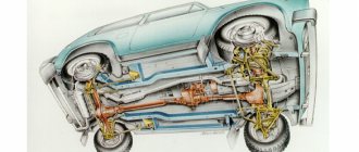
Repair and adjustment of the steering mechanism of a VAZ-21213 car
Removing the steering mechanism and adjusting the gap in the worm bearings
We carry out the work on an inspection ditch or a lift.
We remove the bolt securing the lower cardan joint of the intermediate steering shaft to the steering gear worm shaft (see Removing the steering column).
We hang out and remove the left wheel.
We press the ball pins of the rods out of the bipod holes: middle and side.
Using a 17mm socket, unscrew the nut of the bolt securing the steering gear housing to the left side member
...holding the bolt from turning with a wrench of the same size
Similarly, unscrew and remove the other two bolts securing the steering gear housing.
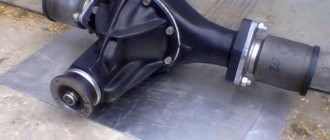
A rubber sealing sleeve is inserted into the hole in the front panel through which the worm shaft passes.
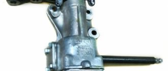
The clearance in the worm bearings is determined by the change in the distance between the end of the steering gear housing and the mark on the worm shaft when the shaft is turned in different directions.
To adjust the clearance in the worm bearings, clamp the crankcase in a vice and use a “13” key to unscrew the four bolts securing the bottom cover
Remove the cover and shims
We reduce the gap in the worm bearings by removing the gasket or replacing it with a thinner one
We install the steering mechanism in the reverse order, without fully tightening the nuts of the crankcase mounting bolts.
We secure the steering rods and the intermediate steering shaft.
An assistant turns the steering wheel two or three times to the right and left until it stops.
At the same time, we check the installation of steering components in their standard places.
Tighten the nuts of the crankcase mounting bolts completely.
Removing the steering gear bipod
Use a 30mm socket to loosen the bipod mounting nut.
Removing the steering mechanism from the car
Use a puller to press the bipod off the shaft
If there is no puller, we dismantle the bipod using the impact method.
We rest the bipod shaft against a wooden block.
We press the bipod on one stop with a sledgehammer, and hit the second with a hammer.
In some cases, you have to cut the bipod with a cutting machine.
The bipod is installed on the conical splines of the shaft in only one position: when the double groove of the bipod coincides with the double spline of the shaft
Adjusting the clearance between the roller and the steering worm
We make the adjustment when we detect free play of the bipod of the steering mechanism.
Before adjustment, you must make sure that there is no axial movement of the worm in the bearings.
The vacuum booster has been removed for clarity.
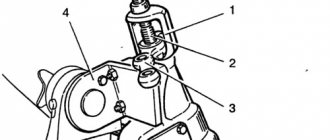
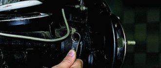
Use a slotted screwdriver to pry off the cap of the bipod shaft adjusting screw nut
Using a 19mm spanner, loosen the nut of the bipod shaft adjusting screw and use a slotted screwdriver to pry off the lock washer.
The lock washer fits into the groove of the adjusting screw with a tendril.
The washer is prevented from turning by a boss on the steering gear housing cover (for clarity, the nut has been removed).
Lifting the washer (we release it from engagement with the tide)
Using a plate (bent at a right angle), we tighten the adjusting screw until the gap in the engagement of the roller with the steering gear worm is eliminated.
Holding the screw from turning with a plate, use a 19mm wrench to tighten the nut.
The steering wheel turning force when installing the front wheels on a smooth plate should not exceed 196 N (20 kgf).
Source
Repair and assembly
Correct and timely maintenance of the steering gear is the key to long-lasting and reliable operation, but there are times when breakdowns do occur. In this case, repairs with complete or partial disassembly simply cannot be avoided. When repairing, it is necessary to pay attention to some features and important points, the use of which will increase the reliability of the mechanism and improve its characteristics.
Steering gear repair
To remove and disassemble the gearbox, it is necessary to hang the front of the car and remove the steering rods. From inside, unscrew the bolt securing the supply shaft from the gearbox shaft. Next, we disconnect the gearbox from the spar by unscrewing the three bolts with spanners. In the engine compartment, remove the hoses and parts that are located in the line of the steering rods.
When the gearbox is unscrewed and removed from the shaft in the cabin, we pull it out of the engine compartment by turning the bipod to the left. Particular attention should be paid to the condition of the gaskets, their location and degree of wear. An unreliable seal can lead to loss of lubrication or contamination of internal cavities. The next step is to unscrew the plug and remove the oil from the steering gear housing, after which you need to unscrew the bipod.
We place the gearbox on a stand made of two boards so as not to damage the shaft splines and unscrew the nut, then remove the bipod. Additionally, you can screw the nut onto the shaft until the ends are mutually aligned. Next, disconnect the steering gear cover by gradually unscrewing the locknut of the adjusting bolt and remove the cover, gradually moving it towards the worm.
Do-it-yourself adjustment of the VAZ 21213 steering gear
If there are any malfunctions in the steering (knocks, increased free play of the steering wheel or, conversely, its tight rotation, etc.), inspect the steering parts. Carry out the inspection on an overpass or inspection ditch in the following order.
1. Clean the steering gear parts and steering gear housing from contamination. Set the wheels to a position suitable for driving in a straight line. 2. When turning the steering wheel in both directions, make sure that: – the free play of the steering wheel does not exceed 5° (when measured along the wheel rim, no more than 18–20 mm). When performing this operation, use tool 67.8720.9501; – there are no knocks in the hinges, joints and steering mechanism; – fastening the steering gear housing and the pendulum arm bracket firmly (if necessary, tighten the threaded connections); – there is no free play in the ball joints of the rods and in the bracket of the pendulum arm, and the worm shaft does not move in the axial direction; – the turning force of the steering wheel (when installing the front wheels on a smooth plate does not exceed 196 N (20 kgf), 245* N (25* kgf). 3. Turning the adjusting clutches of the side links, make sure that their clamps are securely tightened. 4. Check the condition ball joints and protective caps (see subsection 5.2.1).
There are two options for installing the bipod shaft roller: on a needle or on a ball bearing. The text gives numerical data for both options, while under the sign * they refer to the first option (the bipod shaft roller is mounted on a needle bearing).
VAZ-21213 (Niva). Checking the steering rod ball joints
1. First of all, check the movement of the rod tips along the axis of the fingers. To do this, using the lever and support, move the tip parallel to the axis of the finger. 2. The axial movement of the tip relative to the finger should be 1–1.5 mm. This movement indicates that the pin insert is not jammed in the rod tip socket and moves along with the pin, compressing the spring. Replace the hinge with a jammed insert. 3. Turning the steering wheel in both directions, check by touch that there is no free play in the steering rod joints. If you feel free play in the ball joint, replace the tie rod ends or tie rod assembly. 4. Check the condition of the protective caps of the steering rod ball joints. 5. If the protective caps are in good condition and ensure cleanliness inside the hinges, then the service life of the latter is almost unlimited. When moisture, dust, etc. gets into the hinge, premature wear of its parts occurs. 6. The cap must be replaced if it has cracks, tears, or if lubricant penetrates out when squeezing it with your fingers.
VAZ-21213 (Niva). Clearances in steering worm bearings
1. Set the front wheels to the straight-line motion position and, turning the steering wheel in one direction or the other, check whether the distance between the end of the crankcase 8 (see Fig. Section of the steering mechanism) and mark B marked on the steering gear worm shaft does not change. A change in distance is a sign of clearance in the worm bearings. 2. To adjust the clearance in the worm bearings, turn the steering wheel to the left side 1–1.5 turns, unscrew the bolts securing the bottom cover 19 and drain the oil from the steering gear housing. Remove the bottom cover, remove one of the shims 18 or replace it with a thinner one.
Warning The shims are supplied in spare parts with a thickness of 0.10 and 0.15 mm.
3. After securing the bottom cover, check again to see if there is any axial movement of the worm in the bearings. If there is no movement, fill the steering gear housing with 0.215 liters of transmission oil. 4. Check the steering wheel turning force by placing the front wheels on a smooth metal plate. It should not exceed 196 N (20 kgf), 245* N (25* kgf). There are two options for installing the bipod shaft roller: on a needle or on a ball bearing. The text gives numerical data for both options, while under the sign * they refer to the first option (the bipod shaft roller is mounted on a needle bearing).
VAZ-21213 (Niva). Gap in the engagement of the roller with the steering worm
1. After making sure that there is no axial movement of the worm in the bearings, use a puller A.47035 to press the ball joint fingers out of the holes in the bipod and disconnect the rods from the bipod, while maintaining the straightness of the front wheels. 2. By rocking the bipod by the head, check if there is any play in the engagement of the roller and the worm. Within the range of turning the steering wheel by 30° in each direction from the neutral position, there should be no gap, that is, noticeable free play of the bipod. 3. If you feel free movement of the bipod, remove cap 3 (see Fig. Section of the steering mechanism), loosen nut 4 of the adjusting screw and, lifting the washer, tighten adjusting screw 2 until the gap is eliminated. 4. Do not over-tighten the adjusting screw. Then, holding the adjusting screw with a screwdriver, tighten nut 4. 5. After making sure that the bipod does not move, connect the ball joint pins to it. Check the steering wheel turning force. If it exceeds 196 N (20 kgf), loosen the adjusting screw 2 and put on the cap 3.
Steering play
Reg.: 06/09/2009 Threads / Messages: 2 / 152 From: Sochi Age: 35 Car: VAZ-21213, 1999
Name: Yaroslav Reg.: 03/21/2012 Threads / Messages: 3 / 8252 From: Taganrog Age: 30 Car: VAZ-21214-50-120 (06/01/2012), SHTAT UniComp 400L (firmware 3.3.1), VAZ-11173 2012, VAZ-21112 2006
Reg.: 12/23/2011 Threads / Messages: 1 / 46 From: Moscow. Age: 41 Car: VAZ 21213 1998
I noticed this thing. When the steering wheel is straight (the wheels are straight), the steering wheel play is about 5cm. And in the extreme positions of the steering wheel (all the way to the left or right), the steering wheel dangles almost half its turn.
As I understand it, the steering gear needs to be changed for good reason. Or is this normal for the field?
Added after 1 minute 42 seconds:
Yes. forgot. The steering linkages are new (recently changed), the ball joints are also fresh and there is no play in the wheel bearings, the pendulum arm is new.
Reg.: 06/27/2007 Messages: 1765 From: Moscow Age: 53 Car: 21213, 1999
Reg.: 12/23/2011 Threads / Messages: 1 / 46 From: Moscow. Age: 41 Car: VAZ 21213 1998
Disassembly
Drain the oil from the steering mechanism and secure it to the bracket A.74076/R with support A.74076/1.
After unscrewing the nut securing the steering bipod 2 (Fig. 5-5) and removing the spring washer, use puller A.47043 to remove the bipod (Fig. 5-6). Having unscrewed the fastening bolts, remove the cover 12 (Fig. 5-5) of the steering gear housing together with the cap, adjusting screw 8, adjusting plate 9, lock washer 10 and lock nut. Remove the bipod shaft 7 assembled with the roller from the steering gear housing 1.
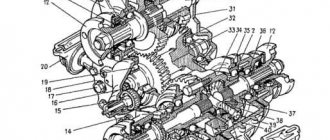
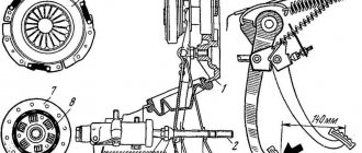
Rice. 5-5. Steering gear parts:
1 – crankcase; 2 – bipod; 3 – lower crankcase cover; 4 – adjusting shims; 5 - outer ring of the worm shaft bearing; 6 – separator with balls; 7 – bipod shaft; 8 – adjusting screw; 9 – adjustment plate; 10 – lock washer; 11 – worm shaft; 12 – upper crankcase cover; 13 – sealing gasket; 14 – bipod shaft bushing; 15 – worm shaft oil seal; 16 – bipod shaft seal.
Rice. 5-6. Removing the bipod:
1 – puller A.47043; 2 – steering bipod shaft; 3 – bipod; 4 – bracket A.74076/R.
Having unscrewed the fastening bolts, remove the cover 3 of the thrust bearing of the worm shaft together with the adjusting shims 4.
Using the worm shaft 11, push the outer ring 5 of the bearing out of the crankcase and remove the shaft together with the bearing cage 6. Remove oil seal 15 of the worm shaft and oil seal 16 of the bipod shaft.
Using mandrel 67.7853.9541, remove the outer ring of the upper bearing (Fig. 5-7).
Rice. 5-7. Removing the outer ring of the upper worm bearing using puller 67.7853.9541:
1 – steering gear housing; 2 – outer ring of the upper bearing of the worm; 3 – mandrel 67.7853.9541.
Detailed instructions for installing electric power steering on a Niva
The procedure for installing the EUR with your own hands is as follows:
- First you need to disconnect the battery.
- Then the plug is removed from the steering wheel, the fixing nut is unscrewed, and the steering wheel itself is dismantled. You also need to unscrew the four screws and remove the plastic cover.
- The mounting bolts are unscrewed and the instrument panel is dismantled. Disconnect the steering column switch plug, unscrew the bolt that secures it, and then remove the device.
- Then the ignition switch wiring is disconnected, the device itself is removed, to do this, unscrew the two mounting screws and turn the key to position I.
- The next step is to dismantle the steering column; to do this, you need to unscrew the steering shaft screw, as well as several mounting screws and nuts. Please note that Nivas use screws with shear heads, so the best option would be to apply notches using a chisel and unscrew them with pliers. Next, the column itself must be lowered down and then dismantled.
- After this, unscrew the nuts on the mounting blocks with fuses and remove them. Also remove the relay cover located under the instrument panel.
- The interior and engine compartment are separated from each other by a partition; it has an elastic plug, which must be removed. The EUR wire is pulled through the hole. Make sure that the laid wire does not come into contact with moving components of the wiper motor.
- Under the dashboard itself, to the left of the steering wheel, there is an 8-pin connector, two gray wires are connected to it. The yellow-blue one from the EUR should be connected to this connector. Then, to the red block, which comes from the tidy, you need to connect the orange and blue-pink wires from the electric amplifier. Here, behind the instrument panel, you can find a ground bolt; you should connect the minus to it.
- An amplifier bracket is installed under the tidy; the wiring from the ignition switch should be threaded into it.
- Next, an intermediate shaft should be installed on the splines of the amplifier itself; remember that a ground should be connected to it in advance. The shaft itself should be securely fixed to the steering gear shaft and the EUR should be attached to the bracket. The shaft must not be pinched or too tight.
- The assembly itself is fixed to the plate using two bolts and two studs; it is advisable to install nuts under them.
- Next, the power and information connectors are connected to the amplifier.
- In fact, the installation procedure can be considered complete. Now you need to reinstall the ignition switch and steering column switch. To install the steering column trim, it will need to be cut, for example, with a hacksaw. The steering wheel and dashboard are put in place. Then the wiring is pulled from the power steering unit to the battery. Please note that in the existing plug in the partition between the engine compartment and the passenger compartment, it will be necessary to increase the size of the hole. Perform a functional check of the equipment and check all connections again.
In the video below you can watch how a self-installed power steering works (the author of the video is Vladislav Mantula).
Assembly
Assemble the steering mechanism on bracket A.74076/R in the reverse order of disassembly.
Press the outer ring of the upper bearing of the worm using mandrel 67.7853.9541, moving the nozzle on the mandrel handle to the opposite side.
After installing the worm in the steering gear housing and securing the bottom cover (Fig. 5-8), check the friction moment of the worm using a dynamometer 02.7812.9501 and head A.95697/5 (Fig. 5-9); it should be in the range of 19.6-49 N cm (2-5 kgf cm). If the torque is less than specified, reduce the thickness of the adjusting shims 2 (Fig. 5-8), and if more, increase it.
Rice. 5-8. Installing the steering gear worm:
1 – bearing cover; 2 – adjusting gasket; 3 – worm.
Rice. 5-9. Monitoring the friction torque of the worm with a dynamometer:
1 – worm; 2 – head A.95697/5; 3 – dynamometer 02.7812.9501; 4 – stand bracket for repairing the steering mechanism; 5 – steering gear housing.
After installing the bipod shaft, check that there is no play in the engagement of the roller with the worm in the positions of the worm shaft turned to the right and left by 30° from the neutral position of the bipod. Eliminate any possible gap in engagement using adjusting screw 2 (Fig. 5-2) and tighten locknut 4.
After adjusting the gap in the engagement of the roller and the worm, use a dynamometer to check the friction moment of the worm shaft, which should be equal to 68.7-88.3 N cm (7-9 kgf cm) when turning the worm shaft 30° both to the left and to the right , from the middle position and should decrease smoothly to 49 N·cm (5 kgf·cm) when turning from an angle of 30° to the stop.
Upon completion of assembly, check the angles of rotation of the bipod from the neutral position, which should be 32°10'±10 both left and right, until the bipod rests on the bolt heads; Fill the steering gear housing with 0.215 liters of transmission oil.
Detailed instructions for installing electric power steering on a Niva
The procedure for installing the EUR with your own hands is as follows:
- First you need to disconnect the battery.
- Then the plug is removed from the steering wheel, the fixing nut is unscrewed, and the steering wheel itself is dismantled. You also need to unscrew the four screws and remove the plastic cover.
- The mounting bolts are unscrewed and the instrument panel is dismantled. Disconnect the steering column switch plug, unscrew the bolt that secures it, and then remove the device.
- Then the ignition switch wiring is disconnected, the device itself is removed, to do this, unscrew the two mounting screws and turn the key to position I.
- The next step is to dismantle the steering column; to do this, you need to unscrew the steering shaft screw, as well as several mounting screws and nuts. Please note that Nivas use screws with shear heads, so the best option would be to apply notches using a chisel and unscrew them with pliers. Next, the column itself must be lowered down and then dismantled.
- After this, unscrew the nuts on the mounting blocks with fuses and remove them. Also remove the relay cover located under the instrument panel.
- The interior and engine compartment are separated from each other by a partition; it has an elastic plug, which must be removed. The EUR wire is pulled through the hole. Make sure that the installed wire does not come into contact with moving components of the wiper motor.
- Under the dashboard itself, to the left of the steering wheel, there is an 8-pin connector, two gray wires are connected to it. The yellow-blue one from the EUR should be connected to this connector. Then, to the red block, which comes from the tidy, you need to connect the orange and blue-pink wires from the electric amplifier. Here, behind the instrument panel, you can find a ground bolt; you should connect the minus to it.
- An amplifier bracket is installed under the tidy; the wiring from the ignition switch should be threaded into it.
- Next, an intermediate shaft should be installed on the splines of the amplifier itself; remember that a ground should be connected to it in advance. The shaft itself should be securely fixed to the steering gear shaft and the EUR should be attached to the bracket. The shaft must not be pinched or too tight.
- The assembly itself is fixed to the plate using two bolts and two studs; it is advisable to install nuts under them.
- Next, the power and information connectors are connected to the amplifier.
- In fact, the installation procedure can be considered complete. Now you need to reinstall the ignition switch and steering column switch. To install the steering column trim, it will need to be cut, for example, with a hacksaw. The steering wheel and dashboard are put in place. Then the wiring is pulled from the EUR to the battery. Please note that in the existing plug in the partition between the engine compartment and the passenger compartment, it will be necessary to increase the size of the hole. Perform a functional check of the equipment and check all connections again.
Also interesting: Why the Chevrolet Niva won’t start. Ways to solve problems.
In the video below you can watch how a self-installed power steering works (the author of the video is Vladislav Mantula).
Removing the steering mechanism and adjusting the clearance in the worm bearings
We carry out the work on an inspection ditch or a lift.
We remove the bolt securing the lower cardan joint of the intermediate steering shaft to the steering gear worm shaft (see Removing the steering column).
We hang out and remove the left wheel.
We press the ball pins of the rods out of the bipod holes: middle and side.
2. Using a 17mm socket, unscrew the nut of the bolt securing the steering gear housing to the left side member
3. ...holding the bolt from turning with a wrench of the same size.
Similarly, unscrew and remove the other two bolts securing the steering gear housing.
5. Remove the steering mechanism.
6. A rubber sealing sleeve is inserted into the hole in the front panel through which the worm shaft passes.
7. The clearance in the worm bearings is determined by the change in the distance between the end of the steering gear housing...
8. ...and a mark on the worm shaft when turning the shaft in different directions.
9. To adjust the clearance in the worm bearings, clamp the crankcase in a vice and use a “13” key to unscrew the four bolts securing the bottom cover.
11. ...and shims.
We reduce the gap in the worm bearings by removing the gasket or replacing it with a thinner one
We install the steering mechanism in the reverse order, without fully tightening the nuts of the crankcase mounting bolts.
We secure the steering rods and the intermediate steering shaft.
An assistant turns the steering wheel two or three times to the right and left until it stops. At the same time, we check the installation of steering components in their standard places.
Tighten the nuts of the crankcase mounting bolts completely.
Do-it-yourself removal, installation and repair
To repair or replace a switchgear element, it is necessary to dismantle the worm assembly.
- locksmith's key to "17";
- tool set 1/2 with ratchet and sockets;
- slotted screwdriver.
- portable lamp to illuminate the repair area.
Dismantling sequence:
- Place the Niva on a lift or inspection ditch. To ensure safety, we use wheel chocks.
- Remove all working fluid from the system.
- Unscrew the fastening bolt of the lower end of the universal joint.
- Jack up the front part of the car and remove the left wheel.
- We remove the hinge joints of the middle and side rods from the mounting holes of the bipod. For the convenience of further work, we recommend moving the side rod to the side.
- Using the head at “19” we unscrew the high pressure hose.
- Remove the sealing copper washers.
- Using a socket set to “22”, unscrew the bolt-fitting of the tip of the fluid supply hose to the radiator.
- Next, loosen the nuts of the bolts securing the steering gear housing to the spar. Remove all mounting bolts.
- Carefully remove the thrust washers that are located between the steering gear housing and the left side member of the vehicle body. When reassembling in reverse order, be sure to put them back in place.
- After this, you should remove and unfasten the middle thrust ball pin from the bipod.
- Remove the steering gear.
- Assembling the steering mechanism should be done in the reverse order. Without fully tightening the fasteners, check that the entire system is working and that there are no distortions.
- Required tightening torques for steering gear nuts:
- worm gear housing mounting nut: 33.3-41.2 Nm;
- steering link ball pin nut: 42.1-63 Nm;
- bipod nut: 199.9-247 Nm.
After assembling all the parts and tightening the fasteners, it is necessary to bleed the power steering.
Note! Before tightening the worm gear housing mounting bolts, adjust the position of the steering gear so that the angle “a” indicated in the figure below is 28°.
The worm drive oil seal is installed in the steering gear cover itself on the passenger compartment side of the car. When servicing and repairing the drive unit with your own hands, you must:
- Replace all O-ring seals of the support bearings in the housing.
- replace the worm seal.
The oil seal has dimensions: 20*30*7 mm. The selection of a new oil seal must be done in an auto shop according to the old model.
Steering gear design on Niva
But before we start shamanism with a tambourine, a few words about the design of that very steering gearbox. The Shaitan machine, although not cunning in its design delights, still requires ingenuity and understanding from anyone who decides to repair it.
The picture was stolen from the Internet (c) who knows?
- Carter
- Bipod
- Lower crankcase cover
- Shims
- Worm shaft bearing outer ring
- Ball separator
- Bipod shaft
- Adjustment screw
- Adjustment plate
- Lock washer
- Worm shaft
- Upper crankcase cover
- Sealing gasket
- Bipod shaft bushing
- Worm shaft seal
- Bipod shaft seal.
During the operation of the columns, worm and roller, namely during their combined operation (friction or rolling as is correct), the operating gap in this pair increases, play appears trivially and some strange knocks and sounds appear.
The appearance of play leads to an increase in the free play of the steering wheel and wobble. And this, in turn, is not normal. Is the steering wheel moving? Poor handling, sensitivity and speed of response are lost, which means safe driving can be kept silent.
I didn’t open America to you here.
This play, if not eliminated in time, namely by not adjusting the steering gear, leads to the appearance of chips, microcracks and subsequent mechanical damage to the main pair - the worm and the bipod.
Well, in the end there comes a complete paragraph and failure. And you, yes, exactly you, end up with your hard-earned tugriks, because a new steering gearbox is less than five, and for Chevrolets with and without power steering, up to a whole ten rubles, in local Chinese spare parts stores, will not cost... checked...
Secrets of the mechanism
In addition, the force is affected by the ball joints and their condition. The VAZ 2121 has four supports, and damage or breakage of even one will lead to poor performance of the entire steering mechanism. Periodic monitoring of the condition of the boots, timely routine replacement of ball boots, and the use of high-quality spare parts have a positive effect on both the reduction of steering effort and the handling of the Niva 2121 as a whole.
A significant influence is exerted by the two front wheels, which rub against the road surface when cornering. The laws of physics and the principles of driving a vehicle cannot eliminate this factor.
In the VAZ steering gearbox, the bipod shaft is equipped with two supports with bronze bushings, the friction between the shaft and the body is increased. Bronze bushings (sliding bearings), due to the fact that the friction coefficient in the steel-bronze pair is quite low. But it is still insufficient to achieve minimal resistance, so great importance is attached to the presence of a sufficient amount of grease in the steering gearbox. On the other hand, it is possible to use needle roller bearings instead of bronze bushings.
The fundamental factor in the operation of the rolling pair is the reduction in the contact area of the moving parts, since the shaft does not touch the supports, but rotates in the housing by means of needles. Only rolling resistance occurs, which significantly reduces the drag coefficient and, accordingly, reduces the force on the steering column.
In addition, the resource of parts and the durability of the steering mechanism increases. Since bronze bushings take the load over the entire surface, and needle bearings only along the rolling line. The hardened steel needles used are capable of withstanding heavy loads occurring in the steering mechanism, depending on the operating conditions of the VAZ 2121.
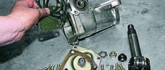
How to disassemble the Niva steering gear
- First of all, the oil should be drained from the gearbox.
- Having disconnected the rods and unscrewed the bolts securing the gearbox to the body spar, remove it from the car.
- We remove the bipod. Unscrew the nut securing it. The bipod usually sticks strongly; to remove it, you should hit it sharply with a hammer.
- Then unscrew the bolts securing the upper cover of the gearbox housing and remove it along with the adjusting shims.
- The outer bearing race should now be pushed out of the crankcase. To do this we use a worm shaft.
- Then we remove the shaft along with the separator.
- Remove the oil seals for the worm shaft and bipod shaft.
Steering column from VAZ 2110 to Niva
As you know, the Niva has a weak steering column; more than once I had the case that they came to repair the Niva with the steering wheel swaying up and down. I read that you can install a “ten” column, but I thought so, why is your own worse? You just need to strengthen it and slightly change the height and angle of the steering wheel. What I eventually achieved was that the steering wheel became two centimeters higher and straighter in the vertical plane. what this gave: the fact is that the driver’s seat will be slightly higher than the standard one, for better visibility from the front, and with the standard version, the knees would rest against the steering wheel and it would not be convenient to turn the steering wheel. Then, due to the greater inclination of the steering wheel to the windshield, the arms get tired due to stretching, so the steering wheel had to be made straighter than in the standard version. So, the progress of the work done: - Unscrew and remove the steering column; — remove the cardan from the steering wheel so that it does not interfere; — after using the “grinder” we cut off the mounting ears flush; - We weld the corners so that they are flush with the entire plane; — weld an additional plate from the bottom; - after that, we make holes and screw it back (I didn’t bother with the holes for the bolts, since one was broken off, and the rear part was generally held on by two M6 bolts, and I decided to specifically weld it) - then we further reinforce it with two ears that are welded from the end of the base of the ignition switch, and also on the other side, but only in place so that they are close to the transverse “stretch” of the struts. and also drill the holes through and screw them in (again, mine are welded) Look at the photos, they are in the order of execution.
Installation of a steering column from 2110 in NIVU
You will need the following parts: 1. Steering column with cardan - bought used at disassembly. 2. Kardanchik Niva - removed from my Niva. 3. One or 2 crosspieces - replaced both at once. 4. steel plate - I cut a piece from 80x80 profile pipe. 5. Steering wheel. 6. Steering column switches assembled. 7. Ignition switch 2110. 8. Steering column switch pads. 9. Steering column cover 2110 or 2114. 2114 for emergency stop button. 10. Terminals mother. 11 Female terminals are narrow 12. Bolts, nuts, washers, electrical tape, wires and everything else that may be needed)
Since the Niva cardan does not match the splines with the steering wheel 2110. First of all, a new cardan is assembled. A flange is required from the cardan 2110 - the crosspiece is knocked out and the required flange is removed. Then the flange is also removed from the Nivsky cardan. And it is replaced by the removed flange from the tenth cardamic. This is where a new cross is required. The bearings are driven carefully using a suitable socket. The bearings are very delicate, so you need to be careful with them. And the edge of the flange is cored. If necessary, the second crosspiece is changed. I had one snacking, and the other was hanging out. Next, the steering column itself is made. Since the Niva’s steering column is shifted to the right by about 40 mm, I decided to correct this at the same time. Two plates were welded onto the 2110 steering column. On the right it is wide, on the left it is narrow and 4 holes are drilled for fastenings.
Or rather, I estimated the width of the plates that I need. Made them. I secured it to the body and attached the steering column to it in place. Then I removed everything together and scalded it.
We install the steering wheel, the mounting of the steering column switches and the steering wheel.
Next you need to connect the steering column switches. With the light switch and turn signals everything is simple. But with the wiper switch everything is more complicated.
2 pigtails with wires are cut off from the original steering column and the cut ends are crimped with terminals and placed in accordance with the diagram into the steering column pads 2108.
Steering column switch pads 2108
The pinout for the turn signal and light switch is as follows:
2108 - Niva - color of the wire cut from the switches Light 56a - 1 - blue-white wire. 56b - 2 - gray-red wire. 56 - 7 - green wire. 30 - 3 - pink wire (I have black).
Just for information on switch 2108 (2110): - blink the headlights - contacts 30 and 56a close - Low beam - contacts 56a and 56 close - High beam - contacts 56b and 56 close.
Turn signals 49aR - 8 - blue wire. 49a - 4 - blue-red wire (I have red-blue) 49aL - 5 - blue-black wire.
Sound signal On the petal of the steering column switch holder - 6 - gray-black wire.
The end result should be a bundle like this.
Harness: light - turn signals - sound signal.
I didn't understand the wiper switch. And I won’t dismantle the original engine. I will assemble it with the 10th windshield wiper motor according to scheme 2110.
I recommend ringing the ignition switch and simply spreading the wires across the contacts. Two wires, if the lock is 2110, simply fold or cut off the information about a forgotten key. There are two options with the emergency button. The first one is left in its native place and transferred to where it is convenient. The second one is more complicated, you take the steering column cover, the hazard warning button 2114. The wires from the original hazard warning button are extended, the pinout is done so that everything works.
Adjusting the Niva steering gear
And so, we disassembled and replaced the worn elements, installed the gearbox on the car and now we can start adjusting.
The order of our actions will be as follows:
- Opening the hood and looking at the gearbox, on the top cover of which there is an adjusting screw and a lock nut, these are what we need.
- Loosen the lock nut and use a flat screwdriver to turn the screw. By tightening the screw clockwise, the backlash in the column gears will decrease, but this is provided that the length of the adjusting screw allows us to tighten it.
If the screw is tightened all the way and the play is not removed, then the column must be replaced.
Maintenance and adjustment of the worm unit
Like any other component, the steering gear requires regular maintenance. Our recommendations will help you avoid large costs for repair work and premature replacement of the unit:
- A seasonal visual inspection allows you to timely detect oil leaks through seals and oil seals, mechanical microcracks and other operational defects of the gearbox frame.
- Timely adjustment of the drive worm clearance will help to avoid increased runout of the entire mechanism, increased noise levels during rotation, and avoid the appearance of a “stiff steering wheel” effect.
- Regular monitoring of the required oil level in the worm gear housing and compliance with oil change intervals based on mileage.
The basic steering gearbox is equipped with a worm pair, in which mechanical friction between the worm and the worm gear occurs during operation.
Reference!
To extend the trouble-free operation life of the unit, it is necessary to use only high-quality lubricant in the gearbox and monitor the condition of the working surfaces.
Adjustment
After the procedure of repairing or replacing the steering worm drive, it is necessary to make adjustment settings.
Checking the steering wheel play must be done on a flat horizontal platform with the required pressure in the car tires. The play, measured by the free play of the steering rim, should be within 5°.
How to set up optimal performance:
- We open the hood and find the unit we need on the left side of the engine compartment (as the vehicle moves). An adjusting screw and a lock nut are installed on the top of the gearbox cover.
- Loosen the lock nut. Using a slotted screwdriver, rotate the adjusting screw clockwise, and the control backlash should decrease.
If the screw is no longer long enough for adjustment, the unit must be replaced.
Important!
Correct and timely maintenance of the steering gear is the key to long-term trouble-free operation in any conditions.
Servicing the Niva steering gear (Chevrolet, 2121, 21213 and 21214)
Like any other component, the steering gear should be maintained by adhering to three simple rules.
Three simple, but at the same time important rules that should always be followed:
- Timely visual inspection.
- Timely control of the oil level in the gearbox.
- Timely adjustment.
Timely visual inspection allows you to quickly identify and detect oil leaks, mechanical defects and other damage to the gearbox housing.
Oil level monitoring – this also includes timely oil changes.
Some craftsmen got the hang of pouring liquid LITOL into the gearbox, having previously melted it on a tile in a vessel.
Good or bad? Everyone decides for themselves. My personal opinion is that this measure takes place in the maintenance of gearboxes whose operational life is approaching sunset. The gaps in the gears can no longer be eliminated by simple adjustment, and the only way out, in order to get rid of the knocking, is to pour liquid lithol into the gearbox housing, thereby leveling the backlash at least a little.
Well, the adjustment allows you to eliminate play in the gearbox gears in a timely manner.
Consistently following the three recommendations above, rest assured that the steering gear in the field will serve you faithfully for more than tens of thousands of kilometers.
Lada 4×4 3D Game Over › Logbook › Replacing the steering gear
Hi all ! after all the spring rides on the hunt, the steering gear finally died; he had already complained about his health before, but this spring finished him off)) there was no desire to repair the old one, so gearbox 21214 was purchased, namely 14, not 13. The difference seems to be that Only in the length of the shaft (10 cm shorter) the rest seems to be identical. I think there is no point in describing the replacement, everything is simple. The difference in the shaft was compensated by digesting the cardan; the old shaft was sawed off and an enlarged one was welded. After installing the gearbox, the steering wheel became very “light” and finally all the play disappeared)))
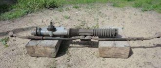
Signs of a faulty steering rack
- A noticeable knock from the rack transmitted to the steering wheel;
- Rack play during rotation;
- Noticeable oil leaks;
- Increasing the applied force to turn.
The manifestation of at least one of the symptoms indicates that it is time to disassemble the steering racks to replace the repair kit and repair worn parts.
The main parts of the mechanism are: support sleeve, gear shaft, spool mechanism.
Schematic illustration of a car's steering rack.
Before troubleshooting, you have to dismantle the rack, which is not equally easy on all cars, and to disassemble it, you cannot do without a special tool. And as the steering rack is disassembled, the repair itself is carried out. Having a little skill in machine repair and a set of tools, it is quite possible to repair a rack with your own hands. And to make this even easier, let’s look at the main steps of how to disassemble the steering rack, and then it’s just a matter of remembering how everything stood and assembling it correctly, since you can disassemble whatever you want, but then putting it back together correctly can be quite problematic. Therefore, if you have not previously had to disassemble the steering rack, I would recommend photographing each step until the steering rack is disassembled.
Recommendations
Comments 18
They are only available for 2121 and 213: The old model has a long shaft, the new model has a short shaft, 214 is already a steering wheel. and those without steering wheel, those come with a regular gearbox 213 Our price tags are: 21210-3400010-00 Steering gearbox 2121 - 2210r 21213-3400010-10 Steering gearbox 21213 VAZ n/o (short shaft) 2513r 21213-3400010-00 Gearbox steering 21213 VAZ s/o (long shaft) 2542r
Steering gearbox 21214 short shaft for the domestic VAZ car. Article 21214-3400010. Price per piece 2439.00 rub.
Of course, I could be wrong, AvtoVAZ has made a lot of hybrids))) But not a single catalog contains 214 gearboxes separately. Here are all the options:
Catalog of spare parts for VAZ-2121 Modifications: 2121, 21211, 21212 - Article: 2121-3400010 and 21212-3400010
Catalog of spare parts for VAZ-21213 catalog 1997 Modifications: 21213, 21214, 21215, 21216, 21217, 21218, 212146 - Article number: 21213-3400010-01
Catalog of spare parts for VAZ-21213-214i catalog 2005 Modifications: 21213, 21214i, 21214-20i, 21215-10, 2129, 2129-01, 2130, 2131, 2131-01, 21312, 21312-01 Article: 21216-3400010 21213-3400010 21216-3400010-10 21213-3400010-10
And the design itself makes it clear to us that we have a 2101 body, 2121 and 21213 bipods, and the length of the shafts was only different.
They are only available for 2121 and 213: The old model has a long shaft, the new model has a short shaft, 214 is already a steering wheel. and those without steering wheel, those come with a regular gearbox 213 Our price tags are: 21210-3400010-00 Steering gearbox 2121 - 2210r 21213-3400010-10 Steering gearbox 21213 VAZ n/o (short shaft) 2513r 21213-3400010-00 Gearbox steering 21213 VAZ s/o (long shaft) 2542r
How can you tell which one is worth it without removing it? I have 213 2002
It can be visually seen that if the shaft is short, the cardan joint connecting to the steering wheel will be almost at the engine shield, with a long shaft it is high and covered by the steering casing
They are only available for 2121 and 213: The old model has a long shaft, the new model has a short shaft, 214 is already a steering wheel. and those without steering wheel, those come with a regular gearbox 213 Our price tags are: 21210-3400010-00 Steering gearbox 2121 - 2210r 21213-3400010-10 Steering gearbox 21213 VAZ n/o (short shaft) 2513r 21213-3400010-00 Gearbox steering 21213 VAZ s/o (long shaft) 2542r
What is the difference between the 2121 gearbox and the 21213 gearbox with the old-style long shaft? Nothing works out?
the bipods are different, the gearbox is the same
That means the 213 won’t fit on the classic Niva 93g?
You have different fist levers and steering bipod, it will get up, but the turning radius and steering will definitely change. Buy a new one and simply replace the bipod from the old one.
I also plan to change the steering gear. What's worse from the 213? what did you buy for?
I also plan to change the steering gear. What's worse from the 213? what did you buy for?
the difference in the shaft is no worse... if you install the EUR, it seems like the shaft needs to be short
for EUR you need a short shaft, or cut and cook a long one)))
I also plan to change the steering gear. What's worse from the 213? what did you buy for?
Adjusting the steering column of VAZ LADA NIVA
Useful tips for do-it-yourself car repairs.
Recommendations from car service specialists and experienced car owners.
Useful tips on car repairs for ordinary drivers and professionals. All the necessary information about repairing and maintaining your car is available in e-books
and
regular printed publications
. Electronic manuals are convenient to use on a computer, smartphone or tablet. They will always be at your fingertips.
How to adjust the steering column of a VAZ.
how to adjust the steering gear of a VAZ-2101-2107, NIVA, some tips on adjustment, tuning and refueling...
It's hard to turn the steering wheel. All reasons. Caster Adjustment of the NIVA steering gear. Suspension diagnostics 2h
Why is it hard to turn (rotate) the steering wheel? How to adjust the steering mechanism (steering gear) and add oil...
Adjusting the steering column of a VAZ or how to remove PLAY ON THE STEERING STEERING
Adjusting the steering column on a classic. https://vk.com/club118003954-our group on VK, subscribe.
Steering column VAZ 2121 Niva
Steering column of VAZ 2121 Niva! In this video I will show and tell you how to change the steering column on a car...
NIVA 4x4 Steering column repair
In one frosty morning, two NIVA 4x4s arrived for repairs. One of them had a broken steering column and a knocking noise…
Replacing the steering column of VAZ 21213 Niva Taiga
https://avto.pro/ - Spare parts without intermediaries. Compare prices for auto parts from 2000 sellers, choose the best offer...
Steering mechanism (gearbox, column) VAZ 21213, 21214 “Taiga” produced by AvtoVAZ (new packaging)
New packaging design Lada Image Unpacking and review: Steering mechanism for VAZ 21213 (Taiga) short shaft (105mm)…
Dismantling the steering gear assembly of VAZ.
In the first part of the video, I pay attention to disassembling the steering gear, the complexity of this operation lies...
Repair of VAZ steering column.
Do you want to learn more about how to repair the steering gearbox on a VAZ? Dismantling the steering gear assembly.
Adjusting the steering column (gearbox) of the VAZ 2106-classic.
Adjusting the steering column (gearbox) of the VAZ 2106-classic.
Watch the video "Adjusting the steering column of a VAZ LADA NIVA."
We share our experience of car repair. A large selection of video clips on the topic “Adjusting the steering column of the VAZ LADA NIVA.”
You will find more detailed information about repairing and maintaining your car in
e-books
and
regular printed publications
.
For those who are accustomed to using regular printed publications, we recommend buying car repair manuals in the online store of the Legion-Avtodata publishing house
Automotive literature stores:
krutilvertel
— Electronic books of printing quality in PDF format
autodata
— Online store of the publishing house Legion-Avtodata