Disassembly
Drain the oil from the steering mechanism and secure it to the bracket A.74076/R with support A.74076/1.
After unscrewing the nut securing the control bipod 2 (Fig. 5-5) and removing the spring washer, remove the bipod using a puller A.47043 (Fig. 5-6). Having unscrewed the fastening bolts, remove the cover 12 (Fig. 5-5) of the steering gear housing together with the cap, adjusting screw 8, adjusting plate 9, lock washer 10 and lock nut. Pull out the bipod shaft 7 assembled with the roller from the steering gear housing 1.
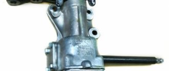
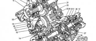
Rice. 5-5. Steering gear parts:
1 – crankcase; 2 – bipod; 3 – lower crankcase cover; 4 – adjusting shims; 5 - outer ring of the worm shaft bearing; 6 – separator with balls; 7 – bipod shaft; 8 – adjusting screw; 9 – adjusting plate; 10 – lock washer; 11 – worm shaft; 12 – upper crankcase cover; 13 – sealing gasket; 14 – bipod shaft bushing; 15 – worm shaft seal; 16 – bipod shaft seal.
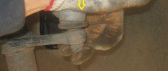
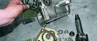
Rice. 5-6. Removing the bipod:
1 – puller A.47043; 2 – steering bipod shaft; 3 – bipod; 4 – bracket A.74076/R.
Having unscrewed the fastening bolts, remove the cover 3 of the worm shaft thrust bearing together with the adjusting shims 4.
Using the worm shaft 11, push the outer ring 5 of the bearing out of the crankcase and pull out the shaft together with the bearing cage 6. Remove oil seal 15 of the worm shaft and oil seal 16 of the bipod shaft.
Using mandrel 67.7853.9541, pull out the outer race of the upper bearing (Fig. 5-7).
Rice. 5-7. Removing the outer ring of the upper worm bearing using puller 67.7853.9541:
1 – steering gear housing; 2 – outer ring of the upper bearing of the worm; 3 – mandrel 67.7853.9541.
Replacing the gearbox
DIY steering rack repair
https://youtube.com/watch?v=—HYiizjMVo
https://youtube.com/watch?v=—HYiizjMVo
When replacing a unit, the labor intensity is lower than when repairing:
- I removed the fastening of the coupled mechanisms, dismantled the gearbox, there is no need to disassemble it;
- During repairs, parts are reassembled, if necessary, the shaft is welded and ground, then we select the oil to fill, and after assembly we tighten the adjusting screw.
Using the Grand Cherokee as an example, replacing the steering gear consists of the following sequence of actions:
- jacking up the front axle and installing it on temporary supports;
- by removing the front left wheel and the fender liner inside the arch, we gain access from below;
- remove the washer tank;
- unscrewing the bolt that secures the steering cardan to the gearbox;
- dismantling the power steering tubes going to the gearbox;
- The bipod of the steering gear and 4 crankcase mounting bolts are removed.
Removing the steering gearbox
Thus, regardless of the design of the gearbox of the steering system of the machine, most often the gap between the transmission parts is adjusted or the entire unit is replaced. For repairs, sets of gaskets and shaft seals, transmission oil and gear packing are produced. The shafts are restored by folk craftsmen; the manuals do not contain information on the dimensions of the seating surfaces, since the unit is considered non-repairable.
Assembly
Assemble the steering mechanism on bracket A.74076/R in the reverse order of disassembly.
Press the outer ring of the upper bearing of the worm using mandrel 67.7853.9541, reversing the nozzle on the mandrel handle with the reverse side.
After installing the worm in the steering gear housing and securing the bottom cover (Fig. 5-8), check the friction moment of the worm using a dynamometer 02.7812.9501 and head A.95697/5 (Fig. 5-9); it should be within the range of 19.6-49 N cm (2-5 kgf cm). If the torque is less than indicated, reduce the thickness of the adjusting shims 2 (Fig. 5-8), and if more, increase it.
Rice. 5-8. Installing the steering gear worm:
1 – bearing cover; 2 – adjusting gasket; 3 – worm.
Rice. 5-9. Controlling the friction moment of the worm with a dynamometer:
1 – worm; 2 – head A.95697/5; 3 – dynamometer 02.7812.9501; 4 – shield bracket for repairing the steering mechanism; 5 – steering gear housing.
After installing the bipod shaft, check that there is no gap in the engagement of the roller with the worm in the positions of the worm shaft turned to the right and to the left by 30° from the neutral position of the bipod. Remove any possible gap in engagement using adjusting screw 2 (Fig. 5-2) and tighten locknut 4.
After adjusting the gap in the engagement of the roller and the worm, check the friction moment of the worm shaft with a dynamometer, which should be equal to 68.7-88.3 N cm (7-9 kgf cm) when the worm shaft is rotated 30° both to the left and to the right, from the middle position and should gradually decrease to 49 N·cm (5 kgf·cm) when turning from an angle of 30° to the stop.
Upon completion of assembly, check the angles of rotation of the bipod from the neutral position, which should be 32°10'±10 both to the left and to the right, until the bipod rests on the bolt heads; Fill the steering gear housing with 0.215 liters of transmission oil.
Source: www.vazbook.ru
Detailed instructions for installing electric power steering on a Niva
The procedure for installing the EUR with your own hands is as follows:
- First you need to disconnect the battery.
- Then the plug is removed from the steering wheel, the fixing nut is unscrewed, and the steering wheel itself is dismantled. You also need to unscrew the four screws and remove the plastic cover.
- The mounting bolts are unscrewed and the instrument panel is dismantled. Disconnect the steering column switch plug, unscrew the bolt that secures it, and then remove the device.
- Then the ignition switch wiring is disconnected, the device itself is removed, to do this, unscrew the two mounting screws and turn the key to position I.
- The next step is to dismantle the steering column; to do this, you need to unscrew the steering shaft screw, as well as several mounting screws and nuts. Please note that Nivas use screws with shear heads, so the best option would be to apply notches using a chisel and unscrew them with pliers. Next, the column itself must be lowered down and then dismantled.
- After this, unscrew the nuts on the mounting blocks with fuses and remove them. Also remove the relay cover located under the instrument panel.
- The interior and engine compartment are separated from each other by a partition; it has an elastic plug, which must be removed. The EUR wire is pulled through the hole. Make sure that the installed wire does not come into contact with moving components of the wiper motor.
- Under the dashboard itself, to the left of the steering wheel, there is an 8-pin connector, two gray wires are connected to it. The yellow-blue one from the EUR should be connected to this connector. Then, to the red block, which comes from the tidy, you need to connect the orange and blue-pink wires from the electric amplifier. Here, behind the instrument panel, you can find a ground bolt; you should connect the minus to it.
- An amplifier bracket is installed under the tidy; the wiring from the ignition switch should be threaded into it.
- Next, an intermediate shaft should be installed on the splines of the amplifier itself; remember that a ground should be connected to it in advance. The shaft itself should be securely fixed to the steering gear shaft and the EUR should be attached to the bracket. The shaft must not be pinched or too tight.
- The assembly itself is fixed to the plate using two bolts and two studs; it is advisable to install nuts under them.
- Next, the power and information connectors are connected to the amplifier.
- In fact, the installation procedure can be considered complete. Now you need to reinstall the ignition switch and steering column switch. To install the steering column trim, it will need to be cut, for example, with a hacksaw. The steering wheel and dashboard are put in place. Then the wiring is pulled from the EUR to the battery. Please note that in the existing plug in the partition between the engine compartment and the passenger compartment, it will be necessary to increase the size of the hole. Perform a functional check of the equipment and check all connections again.
Also interesting: UAZ Ptriot and Chevrolet Niva - comparison of car characteristics
In the video below you can watch how a self-installed power steering works (the author of the video is Vladislav Mantula).
Removing the steering gear and adjusting the clearance in the worm bearings
We carry out the work on an inspection ditch or a lift.
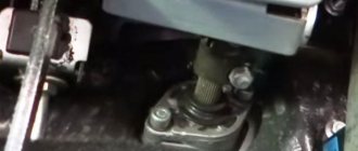
We remove the bolt securing the lower universal joint fork of the intermediate steering shaft to the steering worm shaft (see Removing the steering column).
We hang out and remove the left wheel.
We press the ball pins of the rods out of the bipod holes: middle and side.
1. We move the rods down.
2. Using a 17mm socket, unscrew the nut of the bolt securing the steering gear housing to the left side member
3. ...holding the bolt from turning with a wrench of the same size.
4. Remove the bolt.
Similarly, unscrew and remove the other two bolts securing the steering gear housing.
5. Remove the control mechanism.
6. A rubber sealing sleeve is inserted into the hole in the front panel through which the worm shaft passes.
7. The clearance in the worm bearings is determined by the change in the distance between the end of the steering gear housing...
8. ...and a mark on the worm shaft when turning the shaft in different directions.
9. To adjust the clearance in the worm bearings, clamp the crankcase in a vice and use a “13” key to unscrew the four bolts securing the bottom cover.
10. Remove the cover...
11. ...and shims.
We reduce the gap in the worm bearings by removing the gasket or replacing it with the narrowest one
We install the control mechanism in reverse order, without fully tightening the nuts of the crankcase mounting bolts.
We fix the control rods and the intermediate steering shaft.
The assistant turns the control wheel two or three times to the right and to the left until it stops. At the same time, we check the installation of the steering components in their standard places.
Completely tighten the nuts of the crankcase mounting bolts.
Source: autoruk.ru
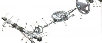
Steering
Steering
The Niva uses a worm-type steering gearbox. It provides reliable vehicle control at any speed and in different road conditions. The worm mechanism is equipped with a globoid type worm (variable shaft diameter) connected to an intermediate shaft and roller. A bipod is installed on the outer part of the roller shaft, which, through rods, activates the rotating mechanism. The rotation of the steering wheel ensures the movement of the bipod through a worm gear; it turns the wheels with rods.
The worm steering mechanism has a low level of sensitivity to shocks and impacts transmitted from the wheels on uneven roads. It has the ability to direct a VAZ vehicle to large turning angles and, accordingly, provides excellent maneuverability of the vehicle. The disadvantage of a worm gear is that it is difficult to manufacture. Worm steering has many connections and therefore requires periodic adjustments and adjustments.
The worm steering mechanism is used on off-road passenger cars with dependent wheel suspension, light trucks and buses. The simplicity of the design has an increased service life and a high degree of maintainability. A slight drawback may seem to be a slightly increased effort on the steering wheel, which occurs for a number of reasons. Having analyzed the design of the steering gear and the loads acting on it, we determine problem areas and ways to solve problems.
The basic one is equipped with a worm pair, which during operation causes steering resistance due to friction between the worm and the worm gear. This is the operating principle of a worm gear; therefore, it is not possible to completely get rid of this factor. The solution is to use high-quality lubricant in the gearbox and monitor the condition of the working surfaces.
The steering gearbox has two rolling bearings (worm shaft), two plain bearings on the bipod shaft (also known as the worm wheel shaft). The bearings themselves, in good and lubricated condition, reduce friction of the main parts (and, accordingly, reduce the force on the steering wheel).
In addition, the pendulum arm, which rotates on two plain bearings and ensures the movement of the steering rack, makes its contribution. The use of high-quality lubricant and periodic monitoring of the condition of boots, connections and rods will reduce the possibility of increased force on the steering wheel.
Thirdly, the six steering fingers must provide a high-quality connection, work correctly in the same planes with the system, and ensure the mobility of the steering mechanism.
How to disassemble the Niva control gearbox
- First, the oil should be drained from the gearbox.
- Having disconnected the rods and unscrewed the bolts securing the gearbox to the body spar, remove it from the car.
- We remove the bipod. Unscrew the nut securing it. The bipod usually gets very stuck; to remove it, you should hit it sharply with a hammer.
- Then we unscrew the bolts securing the upper cover of the gearbox housing and remove it together with the adjusting shims.
- The outer bearing race should now be pushed out of the crankcase. To do this we use the worm shaft.
- After that, we take out the shaft along with the separator.
- Remove the seals for the worm shaft and bipod shaft.
How to remove the steering wheel and steering column of a VAZ-21213 car
Disconnect the negative cable from the battery
Use a slotted screwdriver to pry off the decorative trim of the horn switch cover
Using a 24mm socket, unscrew the steering wheel mounting nut.
To install the steering wheel correctly, you need to mark the position of the steering wheel relative to the shaft
While rocking, pull towards yourself and remove the steering wheel
If the steering wheel sits very tightly on the splines of the upper shaft, then pull the wheel towards you, striking the end of the shaft through a soft metal drift
Removing the steering column
Remove the steering wheel.
Remove the steering column facing covers (see Removing the steering column three-lever switch).
Remove the ignition switch.
Adjusting the Niva steering gear
And so, we disassembled and replaced the worn parts, installed the gearbox on the car and now we can start adjusting.
The order of our actions will look like this:
- Having opened the hood and looked at the gearbox, on the top cover of the housing there is an adjusting screw and a lock nut, which is what we need.
- Loosen the lock nut and use a flat screwdriver to turn the screw. By tightening the screw clockwise, the free play in the column gears will decrease, but this is provided that the length of the adjusting screw allows us to tighten it.
If the screw is tightened all the way, but the free play is not removed, then the column must be replaced.
Removing the side link
We hang and remove the wheel.
To remove the right side rod, turn the steering wheel all the way to the left.
Use pliers to remove the cotter pin
Using a 22mm wrench, unscrew the nut securing the side link to the steering knuckle lever.
Use a puller to press the ball pin out of the lever.
A fork puller can be used.
If there is no puller, unscrew the nut not completely, insert the mounting blade into the spacer between the side rod and the steering knuckle lever and hit the end of the lever with a hammer.
The ball pin can also be pressed out of the lever by striking a sharp blow from below with the back of a hammer on the steering knuckle lever near the hinge
We remove the ball pin from the eye of the steering knuckle lever.
Use a puller to press the ball pin out of the pendulum arm.
The finger can also be pressed out by striking a sharp blow from below with a hammer through a chisel with a blunt end on the pendulum lever.
We take out the right side rod.
Similarly, remove the left side rod.
We install the side link so that a long tip is attached to the steering knuckle lever.
After replacing the rod, we check the wheel alignment (see Angles of the front wheels)
Niva steering gear service (Chevrolet, 2121, 21213 and 21214)
Like any other component, the control gearbox should be maintained by adhering to 3 simple rules.
Three ordinary, but at the same time fundamental rules that should always be observed:
- Timely visual inspection.
- Timely control of the oil level in the gearbox.
- Timely adjustment.
Timely visual inspection allows you to quickly find and identify oil leaks, mechanical defects and other damage to the gearbox housing.
Monitoring the oil level – this also includes timely oil changes.
Some craftsmen got the hang of pouring watery LITOL into the gearbox, having previously melted it on a tile in a vessel.
Great or bad? Everyone decides for themselves. Personally, my worldview is that this measure has room to be used in the maintenance of gearboxes, the operational life of which is approaching sunset. The gaps in the gears can no longer be eliminated by regular adjustment, and the only way to get rid of the knocking noises is to pour watery lithol into the gearbox housing, thereby leveling the free play at least a little.
Well, the adjustment allows you to just right eliminate free play in the gears of the gearbox.
By following the above three tips in turn, be sure that the control gearbox in the field will serve you faithfully for more than tens of thousands of kilometers.
Source: remladavaz.ru
Diagnostics and repair
If the pump stops working, vehicle control is maintained. Liquid flowing through the bypass valve from one cavity to another will practically not interfere with the rotation of the wheels. However, in this case, the steering wheel becomes “heavier”, even compared to cars without a power amplifier. However, this makes it possible to get to the garage or service center.
As a rule, the power steering mechanism is highly reliable and does not require complex maintenance during vehicle operation. Regular checking and cleaning of the boot protection of the steering bipod shaft oil seal, timely replacement of the oil and filter can extend the service life of the power steering for a long time. The causes of most malfunctions encountered during repairs are damage to the seal protection, contamination and, as a consequence, corrosion, failure and leakage of this seal. And untimely replacement of the filter leads to the fact that abrasive particles get into the working fluid - oil, as a result of which the cuffs, as well as parts of the spool valve, wear out."
In general, judging the power steering by durability, we can call it a completely reliable and “tenacious” unit. But still, nothing lasts forever under the sun. Sometimes you have to admit that a node has failed. And, just as we take a broken mechanical watch to a watchmaker, I would like to recommend that owners of expensive trucks entrust the repair of vehicle components and assemblies to specialists. Service specialists often have to deal with attempts to repair the power steering themselves . And this is where problems arise. For example, not everyone knows that replacing the oil seal requires complete disassembly of the unit. Moreover, even with the most careful but unskilled disassembly and reassembly, the internal structure may be damaged. But in general, this is a reliable system, and with qualified maintenance it serves for a long time and without failure.
Diagnostics, service area:
Here you can get a free diagnosis of your steering system. After all, we understand that road safety is the main indicator of efficient vehicle operation.
vote
Article rating
Lada 4×4 3D Game Over › Logbook › Replacing the steering gear
Hi all ! after all the hunting trips in the spring, the control gearbox finally died; he had already complained about his health before, but this spring finished him off)) there was no desire to repair the old one, so the gearbox 21214 was purchased, specifically 14, not 13. The difference seems to be only in the length of the shaft (10 cm shorter) the rest is seemingly identical. I think there is no point in describing the substitution, everything is simple. The difference in the shaft was compensated by digesting the cardan; the old shaft was sawed off and an enlarged one was welded. After installing the gearbox, the steering wheel became very “light” and in the end all the play disappeared)))
FakeHeader
Comments 18
They are only available for 2121 and 213: The old model has a long shaft, the new model has a short shaft, 214 is already a steering wheel. and those without steering wheel, those come with a regular gearbox 213 Our price tags are: 21210-3400010-00 Steering gearbox 2121 - 2210r 21213-3400010-10 Steering gearbox 21213 VAZ n/o (short shaft) 2513r 21213-3400010-00 Gearbox steering 21213 VAZ s/o (long shaft) 2542r
Steering gearbox 21214 short shaft for the domestic VAZ car. Article 21214-3400010. Price per piece 2439.00 rub.
Of course, I could be wrong, AvtoVAZ has made a lot of hybrids))) But not a single catalog contains 214 gearboxes separately. Here are all the options:
Catalog of spare parts for VAZ-2121 Modifications: 2121, 21211, 21212 - Article: 2121-3400010 and 21212-3400010
Catalog of spare parts for VAZ-21213 catalog 1997 Modifications: 21213, 21214, 21215, 21216, 21217, 21218, 212146 - Article number: 21213-3400010-01
Catalog of spare parts for VAZ-21213-214i catalog 2005 Modifications: 21213, 21214i, 21214-20i, 21215-10, 2129, 2129-01, 2130, 2131, 2131-01, 21312, 21312-01 Article: 21216-3400010 21213-3400010 21216-3400010-10 21213-3400010-10
And the design itself makes it clear to us that we have a 2101 body, 2121 and 21213 bipods, and the length of the shafts was only different.
They are only available for 2121 and 213: The old model has a long shaft, the new model has a short shaft, 214 is already a steering wheel. and those without steering wheel, those come with a regular gearbox 213 Our price tags are: 21210-3400010-00 Steering gearbox 2121 - 2210r 21213-3400010-10 Steering gearbox 21213 VAZ n/o (short shaft) 2513r 21213-3400010-00 Gearbox steering 21213 VAZ s/o (long shaft) 2542r
How can you tell which one is worth it without removing it? I have 213 2002
Repair of steering gearbox Niva 21213
Steering gear parts
| 1 – crankcase; 2 – bipod; 3 – lower crankcase cover; 4 – adjusting shims; 5 – outer ring of the worm shaft bearing; 6 – separator with balls; 7 – bipod shaft; 8 – adjusting screw; | 9 – adjusting plate; 10 – lock washer; 11 – worm shaft; 12 – upper crankcase cover; 13 – sealing gasket; 14 – bipod shaft bushing; 15 – worm shaft seal; 16 – bipod shaft seal |
Removing the bipod
| 1 – puller A.47043; 2 – steering bipod shaft; 4 – bracket A.74076/R |
Controlling the friction moment of the worm with a dynamometer
| 1 – worm; 2 – head A.95697/5; 3 – dynamometer 02.7812.9501; | 4 – shield bracket for repairing the steering mechanism; 5 – steering gear housing |
Disassembly
1. Drain the oil from the steering gear housing. Secure the crankcase to bracket A.74076/R with support A.74076/1. 2. After unscrewing the nut securing the control bipod 2 (see Fig. Parts of the steering mechanism) and removing the spring washer, remove the bipod using a puller A.47043 (see Fig. Removing the bipod). 3. Upper bolts securing the clutch housing to the cylinder block. 4. Having unscrewed the fastening bolts, remove cover 12 (see Fig. Parts of the steering mechanism) of the steering gear housing together with the cap, adjusting screw 8, adjusting plate 9, lock washer 10 and lock nut. Pull out the bipod shaft 7 assembled with the roller from the steering gear housing 1. 5. Having unscrewed the fastening bolts, remove the cover 3 of the worm shaft thrust bearing together with the adjusting shims 4. 6. Using the worm shaft 11, push the outer ring 5 of the bearing out of the crankcase and pull out the shaft together with the bearing cage 6. Remove oil seal 15 of the worm shaft and oil seal 16 of the bipod shaft.
| 7. Using a mandrel (3) 67.7853.9541, pull out the outer ring (2) of the upper bearing (1 – steering gear housing). |
Assembly PERFORMANCE ORDER 1. Assemble the steering mechanism on bracket A.74076/R in the reverse order of disassembly. 2. Press the outer ring of the upper bearing of the worm using mandrel 67.7853.9541, reversing the nozzle on the mandrel handle with the reverse side.
| 3. After installing the worm (3) into the steering gear housing and securing the bottom cover (1), check the friction moment of the worm using a dynamometer 02.7812.9501 and head A.95697/5 (see Fig. Monitoring the friction moment of the worm with a dynamometer); it should be within the range of 19.6–49 N cm (2–5 kgf cm). If the torque is less than indicated, reduce the thickness of the adjusting shims 2, and if more, increase it. |
4. After installing the bipod shaft, check that there is no gap in the engagement of the roller with the worm in the positions of the worm shaft turned to the right and left at 30° from the neutral position of the bipod. Remove the possible gap in the engagement with adjusting screw 2 (see Fig. Section of the steering mechanism) and tighten the locknut 4. 5. After adjusting the gap in the engagement of the roller and the worm, check the friction torque of the worm shaft with a dynamometer, which should be equal to 68.7–88.3 N cm (7–9 kgf cm) when turning the worm shaft 30° both to the left and to the right from the middle position and should gradually decrease to 49 N cm (5 kgf cm) when turning from an angle of 30° all the way. 6. Upon completion of assembly, check the angles of rotation of the bipod from the neutral position, which should be 32°10'±1° both to the left and to the right until the bipod touches the bolt heads; Fill the steering gear housing with 0.215 liters of transmission oil.
Niva SUV. Checking and repairing the steering mechanism
1. Carefully inspect the working surfaces of the roller and worm for signs of wear, jamming or scratches. Replace worn and damaged parts. 2. Check the gap between the bushings and the bipod shaft, which should not exceed 0.10 mm. If the gap is larger than indicated, then change the bushings using mandrel A.74105. 3. On the inner surface of the bipod shaft bushings there are spiral grooves that extend only to one side of the bushing. When pressing in the bushings, position them so that their ends, which have groove exits, are inside the crankcase opening, and the groove exits are opposite each other. The ends of the bushings should recess into the crankcase hole by 1.5 mm. 4. Lubricate new bushings with transmission oil before pressing. 5. After pressing into the crankcase, completely machine the bushings with a reamer A.90336 to a size of 28.698–28.720 mm. The installation gap between the bipod shaft and the bushings should be within the range of 0.008–0.051 mm. 6. Check the ease of rotation of the bipod shaft roller on the ball bearing. The worm and roller ball bearings should rotate freely without binding; There should be no wear or damage on the surface of the rings and balls. 7. Check the axial clearance between the head of the adjusting screw 8 (see Fig. Parts of the steering mechanism) and the groove of the bipod shaft 7. The clearance should not exceed 0.05 mm. If it is larger, replace the adjusting plate 9 with a plate of greater thickness.
Warning
Spare parts are supplied with adjusting plates in eleven sizes, widths from 1.95 mm to 2.20 mm; the increase of each size is 0.025 mm.
8. Check the condition of the fixing plates 5 (see Fig. Steering parts). If they are deformed, replace them.
VAZ-21213 (Niva). Dismantling and assembling the steering shaft
1. Unscrew the pinch bolt of the universal joint fork and disconnect the intermediate and upper steering shafts. 2. If the upper shaft or its bearings are damaged, flare the core points of the bracket pipe and pull shaft 15 (see Fig. Control) assembled with bearings 11 out of the pipe. 3. If the shaft rotates in the bearings without jamming and the bearings do not feel circular free stroke (elastic circular movements of the steering shaft are allowed), disassembling the upper steering shaft is not recommended. 4. If the shaft or its bearings are worn or damaged, replace them with new ones. 5. Carry out assembly in the reverse order of disassembly, paying attention to the fact that the locking bolt of the cardan joint passes through the annular groove of the upper shaft. After that, seal the bracket pipe at two points on both sides to secure the shaft bearings.
Source: zinref.ru
Secrets of the mechanism
Steering gear mechanism
In addition, the force is affected by the ball joints and their condition. The VAZ 2121 has four supports, and damage or breakage of even one will lead to poor performance of the entire steering mechanism. Periodic monitoring of the condition of the boots, timely routine replacement of ball boots, and the use of high-quality spare parts have a positive effect on both the reduction of steering effort and the handling of the Niva 2121 as a whole.
A significant influence is exerted by the two front wheels, which rub against the road surface when cornering. The laws of physics and the principles of driving a vehicle cannot eliminate this factor.
In the VAZ steering gearbox, the bipod shaft is equipped with two supports with bronze bushings, the friction between the shaft and the body is increased. Bronze bushings (sliding bearings), due to the fact that the friction coefficient in the steel-bronze pair is quite low. But it is still insufficient to achieve minimal resistance, so great importance is attached to the presence of a sufficient amount of grease in the steering gearbox. On the other hand, it is possible to use needle roller bearings instead of bronze bushings.
The fundamental factor in the operation of the rolling pair is the reduction in the contact area of the moving parts, since the shaft does not touch the supports, but rotates in the housing by means of needles. Only rolling resistance occurs, which significantly reduces the drag coefficient and, accordingly, reduces the force on the steering column.
In addition, the resource of parts and the durability of the steering mechanism increases. Since bronze bushings take the load over the entire surface, and needle bearings only along the rolling line. The hardened steel needles used are capable of withstanding heavy loads occurring in the steering mechanism, depending on the operating conditions of the VAZ 2121.
In the pendulum arm, the plain bearings can also be replaced by rolling bearings. This will increase the sharpness of control, make it easier to control and will contribute to the reliability and durability of the steering mechanism. Periodic monitoring of the condition of the anthers and pins connecting to the rack will increase the service life of parts and maintain the ease of control of the Niva 2121.
Also interesting: Do-it-yourself Niva 2121 elevator: drawings, dimensions
Application of the listed methods and compliance with the rules of periodic monitoring and maintenance will achieve certain results:
- The effort on the steering wheel is reduced at different speeds, when maneuvering in reverse and while parking. This increases the safety of vehicle operation.
- The level of shock transmitted from the wheels to the steering wheel on uneven roads is reduced. The worm gearbox plays a role in this, which reduces the transmission of vibrations and shocks.
- The service life of loaded parts increases, which increases the durability and reliability of the steering gear. If the bronze bushings are replaced with rolling bearings, which have a longer service life and allow you to save the seats.
- The efficiency of the steering gear and the steering mechanism as a whole increases significantly, which helps to increase the service life.
- The force on the steering wheel is reduced, which has a positive effect on driving a VAZ car.