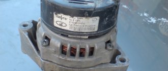
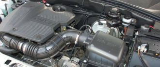
The most basic generator function – battery charge battery and power supply for engine electrical equipment.
Therefore, let’s take a closer look at
the generator circuit , how to connect it correctly, and also give some tips on how to check it yourself.
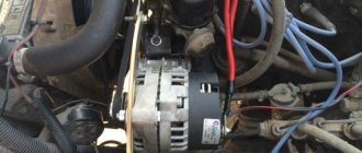
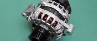
A generator is a mechanism that converts mechanical energy into electrical energy. The generator has a shaft on which a pulley is mounted, through which it receives rotation from the engine crankshaft.
- Accumulator battery
- Generator output "+"
- Ignition switch
- Generator health indicator lamp
- Noise suppression capacitor
- Positive power rectifier diodes
- Negative power rectifier diodes
- Generator "mass"
- Field winding diodes
- Windings of three stator phases
- Field winding power supply, reference voltage for voltage regulator
- Field winding (rotor)
- Voltage regulator
A car generator is used to power electrical consumers, such as the ignition system, on-board computer, car lighting, diagnostic system, and it is also possible to charge a car battery. The power of a passenger car generator is approximately 1 kW. Car generators are quite reliable in operation because they ensure uninterrupted operation of many devices in the car, and therefore the requirements for them are appropriate.
What generators were installed on the VAZ 2107?
Two models of generators were installed on VAZ 2107 cars: G-222 and 37.3701. Until 1987, only one generator G-222 was used. Since 1985, the relay 3 of the signal light 7 has not been installed, and the wires attached to the relay and the signal light have been removed from the wiring harnesses. On these cars, the voltage generated by the generator is controlled by a voltmeter 6. Since 1987, a 37.3701 generator has been installed on some cars. It differed from the G-222 in the data of the rotor and stator windings, the voltage regulator and brush assembly, as well as the design of the rectifier unit.
Comparison of technical characteristics of the generator G-222 and 37.3701
| Generator model | Maximum output current (at 13 V and rotor speed 5000 min1) | Regulated Voltage Limits | Maximum rotor speed | Engine-generator gear ratio |
| Generator G-222 carburetor | 45 A | 14.1 ±0.5 V | 13000 min-1 | 1:2,04 |
| Generator 37.3701 injector | 55 A | 14.1 ±0.5 V | 13000 min-1 | 1:2,04 |
Cars manufactured in 1996 and later (carburetor engines)
The connection diagram for the G222 generator on a VAZ-2107 after 1996 differs from the previous one in one small feature - the power supply to the excitation winding has been changed. Cars have been improved, and some improvements make it possible to kill two birds with one stone - simplify the design and make the fate of the driver easier.
After 1996, instead of a warning lamp, they began to install a voltmeter, which more or less accurately shows the battery charge level. And if the lamp allows you to monitor only the presence or absence of voltage on the generator, then using a voltmeter the driver visually assesses the level. And if necessary, it can understand that repairs or maintenance are necessary.
Generator VAZ 2107 injector model 37.3701
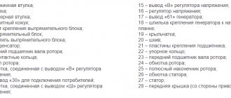
| Item number in the picture | Explanation of position |
| 1 | cap on slip ring side |
| 2 | rectifier unit |
| 3 | rectifier diode |
| 4 | rectifier block fastening screw |
| 5 | slip ring |
| 6 | rear bearing |
| 7 | capacitor |
| 8 | rotor shaft |
| 9 | output "30" magneto |
| 10 | output "61" generator |
| 11 | — terminal “B” of the voltage regulator |
| 12 | voltage regulator |
| 13 | brush |
| 14 | stud mounting the generator to the tension bar |
| 15 | pulley with blades |
| 16 | rotor pole piece |
| 17 | sleeve |
| 18 | front bearing |
| 19 | drive side cover |
| 20 | rotor winding |
| 21 | stator |
| 22 | stator winding |
| 23 | rotor pole piece |
| 24 | buffer bushing |
| 25 | sleeve |
| 26 | clamping sleeve |
Since 1988, the VAZ-2107 has been using a three-phase alternating current generator brand 37.3701 with a built-in rectifier unit and a microelectronic voltage regulator. Some batches of passenger cars may be equipped with generators made in Bulgaria, Slovenia or Germany. These generators are interchangeable with 37.3701 in terms of characteristics and installation parameters, but differ slightly in design.
Useful! VAZ 2107 fuse box
Technical characteristics of generator 37.3701
- Maximum recoil current (at 13 V and rotor speed 5000 min1), A 55
- Limits adjustable voltage, V 14.1 ±0.5
- Highest rotor speed, min-1 - 13000
- Motor-generator gear ratio 1:2.04
CARBURETOR VAZ 2107
Generator diagram VAZ 2107 injector
| Position number on the diagram | Explanation of the position on the diagram |
| 1 | electricity storage |
| 2 | generator VAZ 2107 |
| 3 | fuse and relay block |
| 4 | ignition switch |
| 5 | Battery charging warning light located on the instrument panel |
| 6 | voltmeter |
Generator parts 37.3701 injector
| Position number on the diagram | Explanation of the position on the diagram |
| 1 | voltage regulator complete with brush holder for generators produced since 1996 |
| 2 | voltage regulator and brush holder for generators produced before 1996. |
| 3 | terminal block for output of additional diodes |
| 4 | insulating sleeve |
| 5 | rectifier unit |
| 6 | contact hardware |
| 7 | stator |
| 8 | rotor |
| 9 | spacer sleeve |
| 10 | bearing inner washer |
| 11 | drive side cover |
| 12 | pulley |
| 13 | outer bearing mounting washer |
| 14 | fastening hardware |
| 15 | front rotor bearing |
| 16 | sleeve |
| 17 | cap on slip ring side |
| 18 | buffer bushing |
| 19 | clamping sleeve |
| 20 | capacitor |
| 21 | casing |
| 22 | voltage regulator |
| 23 | base |
| 24 | brush holder |
Generator device 37.3701 for VAZ 2107
This is a three-phase synchronous electrical device with electromagnetic excitation and a built-in rectifier unit based on silicon diodes. The generator rotor rotates using a belt from the engine crankshaft pulley.
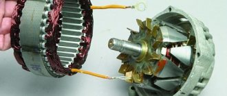
Rotor
The rotor consists of a spindle, on which a steel sleeve and 2 steel beak-shaped poles are placed, which create a magnetic structure. The rotor winding is located on a metal sleeve among the beak-shaped poles in a plastic casing. It is called the field winding. Its ends are connected to contact rings 18 located on a plastic block placed on the rotor shaft. Electricity is supplied to the excitation winding from brushes, which are pressed by springs to the contact rings. The rotor shaft rotates in 2 ball bearings. They are closed type. Lubricant is placed in the bearings at the factory for the entire service life of the generator brand 37.3701 VAZ 2107. The inner ring of the rear bearing is put on the rotor shaft, and the outer ring is squeezed into the rear cover. The other rotor bearing is pressed into the front tire and pressed on both sides with plates with 4 bolts.
Stator
The stator is assembled from metal plates connected by electric welding. The internal grooves of the stator contain 3 phase windings, connected in a star with a neutral wire plug. The variable voltage induced in the stator winding is converted into a constant voltage by the rectifier unit. At the generator, the battery charge indicator lamp is connected to the power supply terminals of the excitation winding.
Rectifier block
The rectifier unit is created using a bridge circuit and consists of 6 power limiting diodes. Which are squeezed into 2 horseshoe-shaped aluminum cooling plates. On one of these plates there are 3 additional diodes, through which the excitation winding of the generator is supplied with electricity after the engine starts. The plates are combined into a rectifier unit attached to the rear tire of the generator.
Helpful! Tightening torques for VAZ 2107
Generator relay 2107 injector
This section describes the generator relay 2107. The generator regulator relay 2107 has a number in the VAZ spare parts catalog - 21080-3701500-00. The figure below shows a VAZ 2107 generator relay.
Generator relay 2107 - electronic, integral. Since 1996 it has been integrated with brushes. The voltage relay is non-separable and cannot be repaired. If it breaks, it must be replaced. It is attached to the back cover of the generator.
How to check the VAZ 2107 injector generator?
Scheme for testing generator 37.3701 on a stand
| Position number on the diagram | Explanation of the position on the diagram |
| 1 | indicator light 12 V, 3 W |
| 2 | generator |
| 3 | voltmeter |
| 4 | rheostat |
| 5 | ammeter |
| 6 | switch |
| 7 | electricity storage |
Connect the electric motor of the stand, set the voltage at the generator output to 13 V using a rheostat and set the rotor speed to 5000 min-1. Let the generator operate in this mode for at least 2 minutes, and then measure the output current. For a working generator it must be at least 55 A.
When the measured size of the supplied current is less, this means that the stator and rotor windings are faulty, the valves are damaged, or the slip rings and brushes are worn out.
The voltage at the generator output is also controlled at a rotor speed of 5000 min-1. The rheostat sets the output current to 15 A and measures the voltage at the generator output; it must be (14.1±0.5) V at an air and generator temperature of (25±10)oC.
When the voltage is not within the specified limits, replace the voltage regulator with a new, serviceable one and repeat the test. If the voltage is normal, then the old voltage regulator is damaged and needs to be replaced.
When the voltage again does not fall within the above limits, you need to check the windings and valves of the generator
Checking the voltage regulator of the VAZ 2107 injector generator
| Position number on the diagram | Explanation of the position on the diagram |
| A | generators have 37.3701 releases since 1996. |
| b | generators have 37.3701 releases before 1996. |
| 1 | battery |
| 2 | output “-” of the voltage regulator |
| 3 | voltage regulator |
| 4 | contact "Ш" of the regulator |
| 5 | contact "B" of the regulator |
| 6 | signal light |
| 7 | contact "B" of the regulator |
Check on the car.
To check, you need to have a DC voltmeter with a scale of up to 15 ... 30 V, accuracy class not lower than 1.0.
When the engine has been running for 15 minutes at average speed with the headlights connected, measure the voltage between terminal “30” and the generator ground. The voltage should be within 13.6... 14.6 V.
If there is a systematic undercharging or overcharging of the battery and the regulated voltage does not fall within the specified limits, the voltage regulator must be changed.
Checking the removed voltage regulator.
The regulator removed from the generator is checked according to the diagram located on this page, just above. The generator regulator 37.3701, used before 1996, must be checked together with the brush holder, since in this case you can immediately find broken brush leads and poor contact between the contacts of the voltage regulator and the brush holder.
Between contacts “III” and “B” of the regulator (or between the brushes on the generator 37.3701) connect a light bulb with a power of 1...3 W, 12 V. To contacts “B” and “C” and to the ground of the regulator, first connect the battery with a voltage of 12 V, and then voltage 15... 16 V.
When the regulator is working, in the first case the light will light up, and in the second case it will go out.
When the light comes on in two cases, there is a breakdown in the regulator; when it does not light in two cases, then there is a break in the regulator or there is no contact between the brushes and the contacts of the voltage regulator (on generator 37.3701 produced before 1996).
Useful! Electrical diagrams of VAZ 2107
000shema_el.jpg
Next, let's get to work:
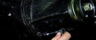
-Remove the unit from the engine and, using the “ten” key, unscrew the nut from terminal “30”. We remove the capacitor wire.
-Unscrew the fastening screw and remove the capacitor.
-Remove the charging relay and the corresponding insulating washer.
-Unscrew the fastening nut from the pulley.
-We disassemble the pulley and impeller.
-Remove the ring installed behind the key.
-Pull the front cover off the rotor shaft
-Remove the adjusting washer (don’t forget to put it back when installing).
-Using the “8” wrench, unscrew the nuts that hold the bearing
-Remove the outer and inner bearing caps.
-Knock out the bearing.
- Press in a new bearing. To do this, you need to apply several light blows through a special mandrel.
-Re-lock the nuts.
-Knock out the anchor from the back cover. We remove it together with the rear bearing.
-If it needs to be replaced, remove it from the rotor shaft.
-Unscrew the three nuts that secure the stator terminals to the diode bridge.
-We take out three bolts from the back cover along with special insulating gaskets.
-Remove the diode bridge and winding.
It is better to replace, if necessary, the diode bridge assembly. We clean all generator parts from dirt, dust and oil. We perform assembly in reverse order.
Alternator belt VAZ 2107
The generator belt has article number 21070-1308020-00 or 21010-1308020-00. The brand 21070-1308020-00 belt has a toothed shape, and the brand 21010-1308020-00 belt has a wedge shape.
Alternator belt size brand 21070-1308020-00
The VAZ 2107 generator belt brand 21070-1308020-00 has the following dimensions:
- Length - 944 mm
- Width - 10.7 mm
- Thickness - 8 mm
Alternator belt size brand 21010-1308020-00
The VAZ 2107 generator belt brand 21070-1308020-00 has the following dimensions:
- Length - 944 mm
- Width - 8.5 mm
- Thickness - 8.8 mm
How to check a VAZ 2107 generator with a multimeter?
Here are ways to check a generator removed from a car. But the same thing can be done on a car. To do this, you need to disconnect the wire from the battery and generator.
Useful! Panel VAZ 2107
How to check a removed VAZ 2107 generator
- Disconnect the wire from the voltage regulator contact;
- We check the rectifier unit with an ohmmeter or using a light bulb and battery. When the resistance on the device goes off scale or the signal light does not light up, it means the valves are working.
- We check the positive and negative valves for breakdown.
We connect the positive lead of the ohmmeter to terminal 30 of the generator, and “-” to its housing. When the ohmmeter shows low resistance or the signal light does not light up, it means 1 or more valves are broken.
- Checking the negative valves.
We connect the “+” of the device with one of the fastening bolts of the rectifier unit, and the “-” with the generator housing. When the resistance is low, it means that 1 or more valves are broken or there is a short stator winding on the generator housing.
- Checking the positive valves.
We connect “+” of the device to terminal 30 of the generator, and “_” to one of the bolts securing the rectifier unit. A small resistance on the device indicates that one of the valves has broken through.
- We check the rotor field windings.
Remove the voltage regulator. Through the window in the generator cover we control the rotor for shortness. To do this, connect 1 ohmmeter probe to the generator impeller, and the other to the contact ring of the field winding.
- We check that there is no break in the excitation winding.
We connect the test probes to the contact rings.
- Checking the capacitor. To do this, we dismantle it. We evaluate the preliminary condition with an ohmmeter. An accurate check is carried out with a special device. We short-circuit the capacitor terminal to the ohmmeter body to discharge it. We connect to the housing contact and the tip of the ohmmeter wire. We switch the ohmmeter to the upper measurement limit. When connected, the arrow must deviate toward “0” and then smoothly return to the end of the scale. When the polarity is changed, the arrow must deviate to “0”
Mounting the generator VAZ 2107 injector
| Item number in the picture | Explanation of the position in the figure | detail number |
| 1 | engraver 10 | 00001-0011983-73 |
| 2 | Nut M10x1.25 | 00001-0021647-21 |
| 3 | bar | 21214-3701635-00 |
| 4 | screw | 21100-3701686-00, 21120-1001294-00 |
| 5 | Bolt M8x25 | 00001-0060436-21 |
| 6 | bolt | 21100-3701376-00 |
| 7 | generator vaz 2107 injector | 21214-3701010-00, 21214-3701010-01 |
| 8 | sleeve | 21214-3701638-00 |
| 9 | Bolt M10x1.25x20 | 00001-0059705-21 |
| 10 | bracket | 21214-3701650-00 |
| 11 | Bolt M10x1.25x35 | 00001-0059709-21 |
Malfunctions
The main malfunctions of the VAZ 2107 generator include:
- brush wear;
- failure of the diode bridge (rectifier unit);
- failure of rotor bearings;
- short circuit in the excitation winding;
- break or short circuit in the stator winding.
Signs of a faulty generator are:
- no indicator light on the dashboard comes on;
- the voltmeter needle is in the red zone;
- sparking inside the generator;
- noise during operation (hum or howl);
- smoke and burning smell coming from the generator.
Do I need to change the generator?
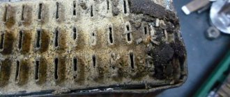
It is quite difficult to determine the cause of generator failure without having a clue about electrical engineering, so in order to repair it, it is better to contact specialists. Most often, in VAZ 2107 cars, the generator fails due to brush wear, which occurs due to an expended resource or mechanical damage to the commutator. In addition, a short circuit or open circuit in the rectifier often occurs, which is “treated” by replacing the diode bridge.
The hum or howl of the generator indicates bearing failure, which can also be repaired. But if suddenly a short circuit occurs in one of the windings, you will have to either negotiate with home-grown specialists about winding a new winding, which is quite risky, or replace the generator with a new one. The last option would be most appropriate here, especially if it also comes with a guarantee.
A new generator, depending on the model and manufacturer, can cost from 2800 to 5000 rubles. Replacing it at a service station will cost about 500 rubles.
The catalog number of the standard VAZ generator for the “seven” is 21083701010.
Generator VAZ 2107 carburetor model G-222
| Position number on the diagram | Explanation of the position on the diagram |
| 1 | voltage regulator |
| 2 | cap on the contact side |
| 3 | rotor |
| 4 | drive side cover |
| 5 | pulley with blades |
| 6 | neutral wire connector |
| 7 | stud securing the generator to the tension plate |
| 8 | generator terminal 30 |
| 9 | voltage regulator housing |
| 10 | terminal 15 of the generator (pin B of the voltage regulator) |
| 11 | capacitor |
| 12 | lag bolt |
| 13 | stator |
| 14 | sleeve |
| 15 | buffer bushing |
| 16 | pressing bushing |
| 17 | rectifier unit |
| 18 | slip rings |
| 19 | rubber ring |
| 20 | brush holder |
Technical characteristics of the generator G-222
- Maximum recoil current (at 13 V and rotor speed 5000 min1), A 45
- Limits adjustable voltage, V 14.1 ±0.5
- Highest rotor speed, min-1 - 13000
- Motor-generator gear ratio 1:2.04
Generator diagram VAZ 2107 carburetor
| Position number on the diagram | Explanation of the position on the diagram |
| 1 | electricity storage |
| 2 | generator VAZ 2107 |
| 3 | battery charging light bulb |
| 4 | Relay and fuse block |
| 5 | ignition lock |
| 6 | battery charging warning light |
| 7 | voltmeter |
Layout of parts for generator G-222
| Position number on the diagram | Explanation of the position on the diagram |
| 1 | brush holder |
| 2 | neutral wire plug terminal block |
| 3 | contact bolt insulating inserts |
| 4 | rectifier unit |
| 5 | contact bolt |
| 6 | stator |
| 7 | rotor |
| 8 | washer |
| 9 | bearing inner washer |
| 10 | drive side cover |
| 11 | pulley |
| 12 | outer bearing mounting washer |
| 13 | pinch bolt |
| 14 | rotor bearing |
| 15 | pressing bushing |
| 16 | cap on the contact ring side |
| 17 | buffer insert |
| 18 | insert |
| 19 | capacitor |
| 20 | base |
| 21 | voltage regulator |
| 22 | frame |
How to check the VAZ 2107 generator carburetor
Scheme for testing the G-222 generator on a stand
| Position number on the diagram | Explanation of the position on the diagram |
| 1 | generator VAZ 2107 |
| 2 | voltmeter |
| 3 | ammeter |
| 4 | rheostat |
| 5 | switch |
| 6 | electricity storage |
Checking the generator relay 2107 carburetor brand G-222
Checking the relay of the generator G-222 VAZ 2107 is carried out according to the diagram shown below in the figure.
| Position number on the diagram | Explanation of the position on the diagram |
| 1 | current storage |
| 2 | contact "-" of the voltage regulator |
| 3 | voltage regulator |
| 4 | output "w" of the regulator |
| 5 | output "B" of the regulator |
| 6 | signal light |
| 7 | contact "B" of the regulator |
Above is a diagram of testing the voltage relay removed from the generator.
Checking the voltage regulator of the G-222 generator of a carburetor engine is similar to checking the voltage regulator of the 37.3701 generator of an injection engine.
The generator relay is checked in the following sequence:
- A 1 - 3 W light bulb is connected to contacts “W” and “B”;
- A source of electricity is connected to terminals “B”, “B” and to the relay ground. First with a voltage of 12 V, and then 15 - 16 V.
- If the regulator is working properly, then in the first case the light should light up, and in the 2nd case it should go out. If the light bulb lights up in two ways, then there is a breakdown in the regulator. When the light does not light in two cases, there is a break or there is no contact between the brushes and the terminals of the regulator.
Circuits for testing rectifier valves
| Position number on the diagram | Explanation of the position on the diagram |
| 1 | voltage regulator |
| 2 | generator rotor |
| 3 | stator winding |
| 4 | rectifier valves |
| 5 | capacitor for protection against overloads and radio interference |
| 6 | signal light |
| 7 | current storage |
| I | control of “+” and “-” valves at once |
| II | control of negative valves |
| III | control of positive valves |
For ease of fastening of rectifier parts, 3 valves have a “+” of rectified voltage on the body. These are “positive” valves, and they are pressed into one plate of the rectifier block. The other 3 valves - “negative” - have a “-” rectified voltage on the body and are pressed into another plate of the rectifier block.
The operating valve allows electricity to flow in one direction. Broken - may not pass current (open circuit) or pass current in both directions (short).
You can check with an ohmmeter or using a 25...40 W light bulb and a battery. First, we check whether there is a short in the “plus” and “minus” valves at once. To do this, connect the “+” of the battery through a light bulb to contact “30” of the generator, and “-” to the generator housing. When the light is on, it means that both the “minus” and “plus” valves have a short one.
The short of the “-” valves can be checked by connecting the “+” of the current source through a light bulb with the terminal block of the neutral wire of the stator winding, and the “-” - with the generator housing. The glow of the light bulb shows a shortness in 1 or several “negative” valves, while the glow of the light bulb may be a consequence of the shortness of the turns of the stator winding on the generator housing. Such a breakdown is less common than short valves. To control the short in the “positive” valves, connect “+” of the battery through a light bulb to terminal “30” of the generator, and “-” to the terminal block of the neutral wire of the stator winding (Fig. III). The glow of the light bulb indicates the shortness of 1 or several “positive” valves.
Mounting the generator 2107 carburetor
| Item number in the picture | Explanation of the position in the figure | detail number |
| 1 | conical spring washer 10 | 00001-0011983-73 |
| 2 | Nut M10x1.25 | 00001-0021647-11 |
| 3 | Nut M10x1.25 self-locking | 00001-0025745-11 |
| 4 | washer | 21010-3701490-00 |
| 5 | bar | 21010-3701635-00 |
| 6 | generator vaz 2107 carburetor | 21080-3701010-00, 21080-3701010-01, 21080-3701010-05 |
| 7 | Bolt M12x1.25x120 | 00001-0055418-21 |
| 8 | Hairpin M10x1.25x20 | 00001-0035461-21 |
| 9 | washer 12 | 00001-0005200-01 |
| 10 | engraver | 00001-0005170-70 |
| 11 | Nut M12x1.25 | 00001-0061015-11 |
| 12 | Bolt M10x1.25x20 | 00001-0059705-21 |
| 13 | bracket | 21050-3701630-00 |
| 14 | Bolt M10x1.25x40 | 00001-0013070-21 |
