Engine ignition system 21129
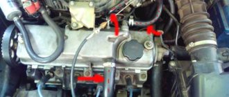
The ignition system of the 21129 engine uses 4 individual ignition coils (Fig. 1).
The ignition system has no moving parts and therefore requires no maintenance or adjustment, with the exception of the spark plugs.
The current in the primary windings of the ignition coils is controlled by a controller that uses information about the engine operating mode received from the sensors of the engine control system.
To switch the primary windings of the ignition coils, the controller uses powerful transistor valves.
Ignition coils
Ignition coils have the following circuits:
Primary winding power circuit
The vehicle's electrical system voltage is supplied from the main relay (ignition relay) to contact “3” of the individual ignition coil.
Ignition coil primary control circuit
The controller switches to ground the circuit of the primary winding of the ignition coil, which supplies high voltage to the spark plugs of the corresponding cylinders:
— contact “1” of the individual ignition coil.
Engine detonation dampening system
To prevent engine failure as a result of prolonged detonation, the ECM adjusts the ignition timing.
To detect detonation, the system has a knock sensor.
The controller analyzes the signal from this sensor and, when detonation is detected, which is characterized by an increase in the amplitude of engine vibrations in a certain frequency range, it adjusts the ignition timing using a special algorithm.
Adjustment of the ignition timing to dampen detonation is carried out individually for the cylinders, i.e. it is determined in which cylinder detonation occurs, and the ignition timing is reduced only for this cylinder.
If the knock sensor malfunctions, the corresponding malfunction code is entered into the controller's memory and the malfunction indicator turns on.
In addition, the controller at certain engine operating modes sets a reduced ignition timing, which eliminates the occurrence of detonation.
Engine cooling fan
The controller controls the relay unit for turning on the electric fan of the engine cooling system.
The electric fan turns on and off depending on the engine temperature.
The electric fan operates in two modes - at maximum speed and at reduced speed.
The reduced speed of the electric fan is activated when the coolant temperature is above 102 °C, as well as when there are DTOZh fault codes in the controller’s memory or when the air conditioner is running.
In this case, the electric fan relay unit is controlled from the “X1.1/H2” contact of the controller.
The reduced speed of the electric fan turns off when the coolant temperature drops below 98 °C.
The maximum performance of the electric fan is switched on when the coolant temperature is above 103 °C, as well as when the refrigerant pressure in the line is high, both with the air conditioner running and the air conditioner not working.
In this case, the electric fan relay unit is controlled from the “X1.1/H3” contact of the controller.
The maximum performance of the electric fan is switched off when the coolant temperature drops below 98 °C.
Engine crankcase ventilation system 21129
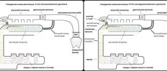
The crankcase ventilation system (Fig. 4) ensures the removal of crankcase gases.
Crankcase gases flow through the exhaust hose into the oil separator located in the cylinder head cover on engine 21129.
The hoses of the first and second circuits are two hoses (one of small diameter, the other of large diameter), through which crankcase gases, having passed through the oil separator, are supplied to the combustion chamber.
The first circuit has a calibrated hole with a diameter of 1.7 mm.
The calibration hole is located in the cylinder head cover tube.
The primary circuit hose (small diameter hose) is connected to the cylinder head cover tube (oil separator fitting).
The primary circuit hose goes from the oil separator to the intake module.
The secondary circuit hose (larger diameter hose) goes from the oil separator to the intake pipe hose.
At idle, all crankcase gases are supplied through the primary circuit nozzle (small diameter hose).
In this mode, a high vacuum is created in the intake pipe, and crankcase gases are effectively sucked into the throttle space.
The jet limits the volume of sucked gases so that engine idle operation is not disrupted.
Under load conditions, when the throttle valve is partially or fully open, a small amount of crankcase gases passes through the primary circuit nozzle.
In this case, their main volume passes through the second circuit (large diameter hose) into the intake pipe hose in front of the throttle pipe and is then burned in the combustion chamber.
If the tightness of the primary circuit hose is broken (air leaks outside the 1.7 mm calibration hole), the ECM erroneously determines an overestimated value of leakage through the throttle valve (the nominal value determined by the manufacturer is 3 - 5 kg/hour), which leads to instability of the idle speed.
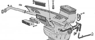
Engine air intake system 21129
Outside air is sucked through the air intake pipe into the resonator and then into the air filter housing.
Air filter 6 (Fig. 5) is used to clean the air from mechanical particles.
The air filter element is a consumable item and has a limited service life.
After the air filter element, the air passes into the intake pipe hose and the throttle pipe.
After the throttle pipe, the air is directed into the channels of the intake module and the intake pipe, and then into the cylinder head and into the cylinders.
The throttle pipe with the electric drive of the distributed fuel injection system is mounted on the intake module. It controls the amount of air entering the intake pipe.
The air supply to the engine is metered by an electrically driven throttle valve controlled by a controller.
The throttle pipe contains two throttle position sensors and an associated electric drive.
The engine intake module 21129 uses a system for changing the length of the intake manifold, which also makes it possible to reduce the toxicity of exhaust gases.
Adjusting the length of the intake manifold ensures better filling of the combustion chamber with air and, accordingly, more complete combustion of the fuel-air mixture throughout the entire engine speed range.
Switching from one length to another is carried out using a pneumatic drive of the air damper axis (Fig. 6) depending on the engine speed and the load on the control of the pneumatic drive, carried out by the ECM controller through the hoses of the pneumatic drive system using the solenoid valve for controlling the damper mechanism of the intake module (Fig. 1.6-03 ).
Idle system (XX)
The controller controls the crankshaft speed at idle speed.
The actuator that meteres the incoming air into the engine is the throttle valve, the opening angle of which at idle is set by the controller depending on the temperature of the coolant, the switched on consumers (air conditioning, heated seats, fan, etc.)
In addition, to maintain the speed, the XX controller controls the speed control and fuel supply.
It is worth remembering that when driving a car with the accelerator pedal released in 1st, 2nd or 3rd gear, the specified idle speed differs from the specified speed of a stationary vehicle and depends on the temperature of the engine coolant.
The state of the engine at idle speed can be determined by the parameters of the current idling correction (“Desired change in torque to maintain idle speed (integral part)”% and Desired change in torque to maintain idle speed (proportional part)”) and the torque adaptation parameter (“Parameter adaptation of idle speed control" %).
The torque adaptation parameter is determined only on a warm engine, but is used as an additive throughout the entire temperature range of engine operation.
Gasoline vapor recovery system
The gasoline vapor recovery system (VAPS) consists of a carbon adsorber with a purge solenoid valve and connecting pipelines.
Gasoline vapors from the fuel tank are supplied to a collection tank (adsorber with activated carbon) (Fig. to retain them when the engine is not running. The vapors enter through the pipe marked “TANK”.
The controller, by controlling the solenoid valve, purges the canister after the engine has operated for a specified period of time from the moment it switches to the closed-loop fuel control mode.
Air is supplied to the adsorber through the “AIR” pipe, where it is mixed with gasoline vapor.
The mixture thus formed is sucked into the engine intake pipe for combustion during the operating process.
The controller regulates the degree of purge of the adsorber depending on the engine operating mode, sending a signal to the valve with a variable pulse frequency (16 Hz, 32 Hz).
The controller constantly monitors the effect of purge (the state of the canister being filled with fuel vapor) on engine operation using signal information from the UDC.
If the adsorber has a high % filling with fuel vapors, the controller reduces the fuel supply (the value of the parameter “Fuel concentration coefficient in the adsorber” is about 2%, respectively, if the % filling with fuel vapors is low, the value of the parameter “Fuel concentration coefficient in the adsorber” is about 0%).
During each trip on a warm engine, the controller checks the condition of the canister purge valve, closing it completely and opening it to a value higher than that set for the given engine operating mode.
Based on the deviation of the fuel supply correction factor, the controller determines the condition of the canister purge valve.
The scan tool displays the duty cycle of the control signal.
A coefficient of 0% means that the adsorber is not purged. A coefficient of 100% means that maximum purging occurs.
The controller turns on the purge solenoid valve when:
— the coolant temperature is above a certain value;
— the system operates in feedback mode based on the oxygen sensor signal;
- the system is working properly.
contents .. 238 239 240 241 ..Lada Vesta (2019). Abundant crankcase gases: causes
The main causes of gases from the engine crankcase:
- Malfunction of the crankcase ventilation system
-Breakthrough of gases into the crankcase
Signs of malfunction of the crankcase ventilation system and valve
The crankcase gas recirculation system has significantly reduced harmful emissions. At the same time, it is quite easy to operate and requires virtually no intervention when repairing the engine. However, like any system, it is also not ideal.
The fact is that a system malfunction is not as obvious as a breakdown of any other engine unit. But when the system fails, it can result in quite large financial losses for the car owner. The breakdown of such a system is not clearly pronounced; the car owner will already notice the immediate consequences of its failure. Signs of failure are usually:
— fogging of system hoses
- increased oil consumption
- valve cover gasket leaking
Presence of oil in the air filter pipes. Excessive gas pressure inside the engine. And the most critical case is the squeezing out of the crankshaft seals. Agree, a silent assistant can lead to big problems.
Gas breakthrough into the crankcase
The breakthrough of gases into the crankcase is associated with excessive oil consumption. Gases do not break into the crankcase, but into the engine valve cover through a torn or crumbled valve sleeve. This happens occasionally. The valve then loses alignment on the seat and does not fit well. Compression in the cylinder drops, the fuel does not burn out completely, but externally and audibly the engine is operating quite normally. Such a malfunction can really be fixed in two hours. You can verify the correctness of the diagnosis by measuring the compression in the cylinders, or, which is easier, with the valve covers removed, see where the gases are coming from. Due to excessive oil consumption, severe leakage through all seals, and smoke from the breather, it is too early to pronounce a “death sentence” on the engine. We need to look into it carefully, not wasting time.
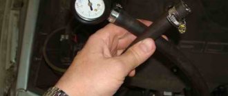
How to check the crankcase ventilation valve
As with any vehicle component, it is necessary to periodically inspect and correct the malfunction. The fact is that the recirculation valve operates in a rather dirty environment. Mandatory, cleaning is necessary. At the slightest suspicion of its malfunction, you need to check its performance. If a valve with additional electronic systems is installed, the vehicle's self-diagnosis may show an error. In more simplified versions, diagnostic skill is required.
1. Connect the ventilation hose to the valve. 2. Start the engine and let it idle. 3. Touch the valve inlet with your finger and make sure there is vacuum. At this moment the valve stem will move. 4. If vacuum is not created in the valve inlet, clean or replace the valve.
How to determine malfunctions of the engine crankcase ventilation system
During operation, excess pressure and gases arise in the crankcase of an internal combustion engine. Crankcase gases contain vapors of fuel, water, oil, etc. Their effective removal is very important, because they can significantly deteriorate the quality and condition of motor lubrication, which usually leads to excessively rapid wear of power unit components. So, to remove these gases, it is customary to use a special crankcase ventilation system. It has already happened historically that today there are two systems: open and closed. Considering that crankcase gases are extremely toxic, it is impossible to vent them outside, so modern cars have used a closed ventilation system for such gases, in which the crankcase gases are burned into the combustion chamber. But due to the excessive pressure of the motor lubricant, oil particles also rise together with the gases, and they must not get into the combustion chamber; it is the separation of oil from gases that is the main task of the ventilation system. This is usually done using special oil traps. If we talk about oil traps, they can be very diverse, but at the same time they all have the same operating principle: to deposit all the heavy lubricant particles on the walls, and let gases through. This is done using labyrinths, vortices and grids. Immediately after separating the lubricant from the gases, the oil flows back into the engine, while the gases are sent to the manifold in small portions, and from there they enter the engine and are burned there. A special valve regulates the supply of gases to the manifold; it can open when there is excess pressure and close when there is a vacuum. On every car, the crankcase ventilation system needs periodic cleaning and inspection. If the system becomes severely clogged, the pressure in the crankcase rises, and as a result, oil may begin to pour out through the dipstick. Typically, this phenomenon indicates a valve malfunction or a clogged oil trap. If the reason is a malfunction of the oil trap, then motor lubricant begins to flow into the combustion chamber, as a result of which the vehicle begins to smoke, a rather unpleasant odor occurs, and when this problem is not corrected in a timely manner, this can lead to a stuck ring. Problems associated with the crankcase ventilation system of the power unit, as well as any other engine problems, are much easier to prevent than to then eliminate the consequences. If the very first cause of failure of the crankcase gas exhaust system occurs, and this is poor separation of lubricant from gases, or excess pressure, repairs must be carried out immediately. Identifying signs indicating a malfunction of the crankcase ventilation system is usually not difficult. If the oil trap is clogged or the valve is broken, then excess lubricant pressure can be detected using a simple check; for this, the neck of the lubricant filler hole is closed with the palm of your hand. If there is excess pressure in the system, then the palm will push away with a force that gradually increases. Well, if the oil catcher breaks down, small particles of engine lubricant get into the pipes on the intake manifold, sometimes they can even settle on the air filter, and, accordingly, the car’s exhaust gases change their color.
contents .. 238 239 240 241 ..
Have oil burns been cured on the 1.8 engine (Lada Vesta, Lada XRAY)
The 1.8-liter engine with the VAZ 21179 index has been produced since February 2016. It is designed for installation in cars of the LADA Vesta and XRAY family. Along with the advent of the new engine, the owners noticed oil burns (increased engine oil consumption). This was confirmed:
- Autoreview magazine during life tests of the Lada XRAY in 2016 (it took 5 liters per 10,000 km);
- magazine "Behind the Wheel" (over 2500 km, the oil level dropped from the middle to below the minimum level).
We decided to find out if this issue has now been fixed. The news will be updated as new information becomes available.
What are the engine oil consumption standards?
AVTOVAZ reported that oil consumption can reach up to 0.7 l/1000 km. And with a sporty driving style it can reach 1.0 l/1000 km.
January 2022
. The news came out that AVTOVAZ modified the 1.8-liter engine (cured it from the oil burn). It was reported that the new modified VAZ 21179 engine eliminates the problem of increased oil consumption. Now all new LADA Vesta and XRAY cars have begun to consume oil in accordance with the established regulations.
May 2022
. Za Rulem experts have recorded increased engine oil consumption on the 2022 Lada Vesta SW Cross. (about a quarter of the level over 3500 km.).
26.08.2019
. Lada XRAY project director Oleg Grunenkov said in an interview:
11.09.2019
. To the question “Have they eliminated the oil burner on 1.8L engines?” We were answered by an AVTOVAZ employee directly involved in the production of VAZ 21179 engines (1.8L, 122HP). He said that this problem has not been completely resolved at the plant.
In November 2022
Lada Vesta project manager Alexey Likhachev told how the plant solved the problem of oil consumption of the 1.8 liter engine. According to him, 5 measures were introduced over the past year.
In February 2022
an information letter has appeared stating that the control value for oil consumption is now no more than 0.5 liters per 1000 km of vehicle mileage.
In the second half of 2022
AVTOVAZ has modified the design of the cylinder head of the VAZ 21179 engine (1.8 l, 122 hp). We started installing other valve guides. Whether this will affect oil consumption is still unknown.
Have you encountered increased oil consumption in the 1.8-liter VAZ 21179 engine? Leave your feedback in the comments, take part in the survey.
Source
Checking the canister purge valve
The control unit is located in the engine compartment, to the left of the expansion tank of the cooling system. The algorithm of actions is as follows:
- We turn off the engine.
- Open the hood.
- Disconnect the block with wires. We check the terminals for oxidation and clean them as necessary.
- We temporarily dismantle the control unit and check the resistance of the equipment with a multimeter (no more than 30 ohms).
- Based on the diagnostic results, we decide on the advisability of replacing the CPA with a new one.
Typical problems
In order to carry out comprehensive diagnostics of the vehicle, seek help from service station specialists. The primary signs of a CPA malfunction are as follows:
- prolonged hissing when unscrewing the fuel tank cap;
- delay in engine response when sharply pressing the accelerator pedal (the so-called kickdown);
- the “Check Engine” indicator lights up on the dashboard and produces system errors: P0443, P0444, P0458, P0459;
- loud knocking of the gearbox when the engine is running;
- Unstable engine speed.
Where is the canister purge valve located?
Topic: engine oil burner 1.8.
Car: Lada Vesta
For those who don’t know, the 1.8 engine has an oil burner. on Lada cars
It occurs immediately after purchase and some cars do not make it to the first maintenance so as not to add oil. The factor of grinding in engine parts also plays a role here, but even after grinding in, the oil burn does not go anywhere and, according to official statements by AVTOVAZ, can amount to up to 0.7 liters per 1000 km.
I remember how everyone scolded and scolded VAG cars for oil consumption, but there it is at least found in turbocharged engines, which are highly boosted, but here it is naturally aspirated.
By the way, this information about oil consumption is not from a bullshit, but from an official letter from AVTOVAZ, which I am traditionally enclosing.
According to Alexey Likhachev, Lada Vesta project manager, it was
5 measures have been introduced to eliminate oil stains.
- The engine calibrations were changed in terms of adjusting the intake phase of the gas distribution mechanism.
- Worked with the valve supplier to tighten tolerances and improve the surface of the valve stems to avoid nicks and premature wear.
- Valve stem seals. Fixed two things. The first is the technical process. The surface quality of the valve stem seal has been improved. The second is the material. It became more elastic and began to fit the valve stem more tightly.
- The design of the oil deflector has been changed. Oil separation now occurs more efficiently.
- We switched from 5w30 to 5w40 engine oil. This is an oil with more viscous characteristics.
In my opinion, the last three points look most effective,
which actually make changes to the operation of the engine in terms of oil consumption. As for the viscosity of the oil, this is debatable. In winter, you will not fill in thick oil, otherwise the engine is more likely to starve of oil. In winter you will still have to fill in thinner oil. And for warm regions, this method will help to slightly reduce oil consumption.
Have oil burns been cured on the 1.8 engine (Lada Vesta, Lada XRAY)
The 1.8-liter engine with the VAZ 21179 index has been produced since February 2016. It is designed for installation in cars of the LADA Vesta and XRAY family. Along with the advent of the new engine, the owners noticed oil burns (increased engine oil consumption). This was confirmed:
- Autoreview magazine during life tests of the Lada XRAY in 2016 (it took 5 liters per 10,000 km);
- magazine "Behind the Wheel" (over 2500 km, the oil level dropped from the middle to below the minimum level).
We decided to find out if this issue has now been fixed. The news will be updated as new information becomes available.
What are the engine oil consumption standards?
AVTOVAZ reported that oil consumption can reach up to 0.7 l/1000 km. And with a sporty driving style it can reach 1.0 l/1000 km.
January 2022
. The news came out that AVTOVAZ modified the 1.8-liter engine (cured it from the oil burn). It was reported that the new modified VAZ 21179 engine eliminates the problem of increased oil consumption. Now all new LADA Vesta and XRAY cars have begun to consume oil in accordance with the established regulations.