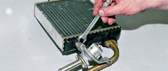
VAZ 21213 and 21314 SUVs use a supply and exhaust ventilation system. While the car is moving, air is forced into the cabin by natural pressure through the air intake slots on the hood. Air leaves the cabin through openings in the rear roof pillars. We will talk about these and other features of the Lada 4×4 heater (stove) further..
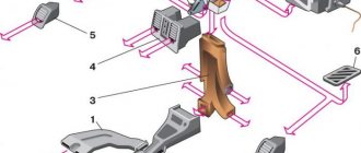
Heater device
1 – side deflector; 2 – side air duct; 3 – air duct for heating the windshield; 4 – central deflectors; 5 – air duct damper cable; 6 – air duct damper; 7 – stove radiator; 8 – radiator seal; 9 – radiator casing; 10 – radiator outlet pipe; 11 – radiator inlet pipe; 12 – stove tap; 13 – air distribution cover; 14 – electric fan casing; 15 – fan impeller; 16 – fan electric motor; 17 – stove tap cable; 18 – windshield heating damper cable; 19 – bracket for heater control levers; 20 – air duct damper control lever; 21 – control lever for the windshield heating flap; 22 – lever for controlling the stove tap.
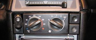
Interior heating
To heat the interior and protect the windshield, door windows and rear window from fogging and freezing:
- move levers 6 and 7 to the right;
- set lever 8 to the middle position;
- open the heater cover with lever 10;
- turn on switch 11 heated rear window;
- If necessary, turn on the electric heater fan with switch 12.
Warm air will be directed both to the driver’s and passengers’ footwells and to the windshield and front door glass. For faster heating of only the windshield, close the heater cover with lever 10 and move lever 8 to the right.
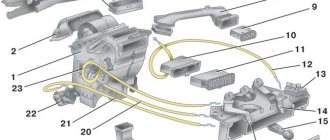
Heater diagram
1 – damper; 2 – electric fan casing; 3 – fan electric motor; 4 – impeller; 5 – heater radiator; 6 – radiator inlet pipe; 7 – radiator outlet pipe; 8 – radiator casing; 9 – air duct damper; 10 – air duct box; 11 – air duct for heating the windshield; 12 – central deflector damper; 13 – central deflector; 14 – crane control lever; 15 – control lever for the windshield heating flap; 16 – air duct damper control lever; 17 – control lever bracket; 18 – windshield heating flap; 19 – windshield heating damper cable.
content .. 100 101 102 103 104 105 106 107 108 109 ..7.11.
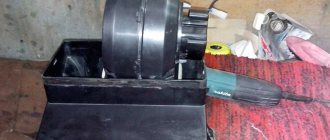
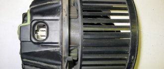
VAZ-21213 (Niva). Heater fan motor
Heater fan motor connection diagram
Electric motor type ME-255 DC with excitation from permanent magnets. When an additional resistor 4 is connected to the power supply circuit of the electric motor, the armature shaft rotates at a reduced frequency. The resistor is secured with two spring washers in the heater fan housing. The resistor value is 1.5 Ohm at 20° C. It is recommended to replace a faulty electric motor with a new one. The only possible repair is cleaning the collector. To disassemble the electric motor, you need to unscrew the screws securing the cover and remove it. Then you should remove the lock washer from the armature shaft and remove the armature from the housing. Assembly is carried out in reverse order. Checking the technical condition is similar to that described above for the windshield wiper motor. Possible malfunctions, their causes and methods of elimination
| CAUSE | REMEDY METHOD |
| The electric motor does not work | |
| Wires are damaged or wire connections are oxidized | Check and restore connections. Replace damaged wires |
| Fuse 1 in the fuse block has blown | Replace the fuse |
| The heater switch is damaged - no voltage is supplied to the switch output terminals | Check the switch, replace it with a new one if necessary |
| Sticking or wear of the motor brushes, a break in the armature winding or contamination of the commutator | Check motor, repair or replace |
| Short circuit to ground in the armature winding - when the electric motor is turned on, the fuse burns out | Replace the motor |
| The electric motor only operates at one speed | |
| Wires are damaged or wire connections are oxidized | Replace damaged wires, strip wire ends |
| Damaged heater switch | Replace the switch |
| Additional resistor burnt out | Replace the resistor |
| Motor armature rotates slowly | |
| Additional resistor burnt out | Clean the commutator, replace the brushes |
| Contamination or oxidation of the commutator, worn brushes | Replace the motor |
| Interturn short circuit in the armature winding | Disassemble the electric motor, clean the shaft journals |
7.11.2. Motor test data
| Shaft rotation frequency when the electric motor is loaded with an impeller at a voltage of 12 V and a temperature of (25±10) °C, min–1 | 3000 ± 150 |
| Current consumption at the specified load and speed, A | no more than 4.5 |
content .. 100 101 102 103 104 105 106 107 108 109 ..
Heating and ventilation system components
The heater fan (ME-255) supplies air to the passenger compartment through air ducts. Its rotation speed is controlled by a three-position switch on the panel.
An additional resistor is designed to reduce the fan rotation speed (intermediate rotation speeds).
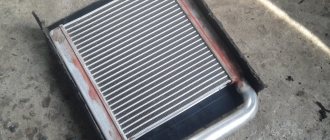
The heater radiator is installed in the passenger compartment under the panel in a plastic case and serves to transfer heat to the interior.
The heater valve is installed at the inlet of the heater radiator and serves to regulate the flow of antifreeze that passes through it.
The damper control levers serve to distribute air flows that are directed into the cabin, as well as to control the heater tap.
The design of the heater has a number of disadvantages, for example, strong fan noise, as well as its low performance. We'll talk about this and other problems in the improvements section.
Keywords: stove 4x4 | 4x4 air ducts
0 0 0 1 2 0
Share on social networks:
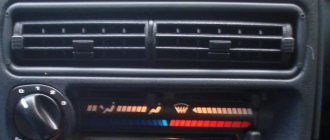
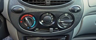
Interior ventilation
Content
Outside air can enter the vehicle interior:
- through open door windows;
- through nozzles 2 (Fig. 1-6) for blowing the windshield, if you move distribution lever 8 and lever 7 for controlling the air supply hatch cover to the right;
- through the side nozzles 1 for blowing the door windows, if you move lever 7 to the right and lever 8 to the left;
- through holes 9 of the heater casing into the driver's and front passenger's foot area, if you open the heater cover with lever 10 and move lever 7 to the right;
- through the central nozzles 5 directly from the air supply box when the car is moving, if the regulators 3 open the nozzle flaps (summer airflow). By moving lever 4 in the horizontal and vertical directions, the direction of the air flow from the nozzle changes.
In the middle position of lever 8 and in the right extreme position of lever 7, air will flow through nozzles 1 and through nozzles 2.
If the car is moving at low speed, you can increase the amount of incoming air by turning on the electric heater fan with switch 12.
How to upgrade the Niva-21213 stove
If you are the owner of a Niva-21213 and are in love with this vehicle, then you are unlikely to give it up if you find some technical defects in it. In principle, this is absolutely correct; you can remain faithful to your “iron horse”, and if defects are identified, try to eliminate them yourself.
Niva-21213, indeed, needs some of your intervention; tuning the Niva stove will not be superfluous at all.
https://www.youtube.com/watch?v=3ch3Fh8Xx38
In the summer, you won’t be able to notice any inconvenience, but with the onset of cold weather, you definitely won’t be able to do without enhanced wardrobe equipment in the form of cotton pants and a jacket.
You don’t want to constantly feel like a “tanker”, so most owners of this car decide to roll up their sleeves and modify the stove of their own Niva. By the way, the same problems are inherent in another domestic model - the UAZ, the owners of which are also actively searching for what to do to improve the performance of the stove.
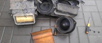
The process of refining the heating system
It is useful to note that modification of the VAZ-2121 stove is not accompanied by high problems. Even a car enthusiast who does not have special technical and repair skills can eliminate such technical defects.
Discounts on new cars! Advantageous loan from 9.9% Installment plan 0%
In addition, modification of the Niva-2121 stove may involve performing a variety of actions, including the most basic ones.
Heating in your car can be improved by even just slightly upgrading the air ducts. If you want to radically improve the heating system and increase comfort, then, of course, you will have to tinker a little more.
Air duct modernization
Unfortunately, if you carefully examine the air ducts that your Niva is equipped with, you will be horrified at how it was possible to install so many cracks in it. Is it possible to expect good heating with such a design?
The answer, of course, is simple, since all the heated air is dispersed under the dashboard, and the interior is heated according to the residual principle.
However, it’s good when a problem is so easily identified, then solving it is much easier. Upgrading the air duct involves applying silicone glue to all joints.
Be prepared for the fact that performing such actions is sometimes quite difficult, since not all places have unobstructed access. You still have to get used to it and apply silicone glue to all the joints.
Electrical diagram of VAZ-2121
1 – side direction indicators; 2 – front lights; 3 – VAZ-2121 headlights; 4 – electric motors for headlight cleaners; 5 – sound signals; 6 – relay for turning on the headlight cleaners and washer; 7 – relay for turning on low beam headlights; 8 – relay for turning on the high beam headlights; 9 – windshield washer electric motor; 10 – sensor of insufficient brake fluid level; 11 – plug socket of a portable lamp; 12 – oil pressure warning lamp sensor; 13 – oil pressure indicator sensor; 14 – coolant temperature indicator sensor; 15 – ignition distributor; 16 – spark plugs; 17 – windshield wiper motor; 18 – ignition coil; 19 – generator; 20 – carburetor shut-off valve; 21 – VAZ-2121 starter; 22 – headlight washer motor; 23 – voltage regulator; 24 – battery charge warning lamp relay; 25 – battery; 26 – windshield wiper relay; 27 – additional fuse block; 28 – main fuse block; 29 – parking brake warning lamp switch; 30 – switch for differential lock warning lamp; 31 – reverse light switch; 32 – switch for the carburetor air damper warning lamp; 33 – brake light switch; 34 – heater electric motor; 35 – relay-interrupter for direction indicators and hazard warning lights; 36 – additional resistor of the heater electric motor; 37 – instrument lighting switch; 38 – headlight switch; 39 – direction indicator switch; 40 – sound signal switch; 41 – wiper switch; 42 – windshield washer switch; 43 – ignition switch; 44 – external lighting switch; 45 – heater switch; 46 – switch for headlight cleaners and washer; 47 – cigarette lighter; 41 – alarm switch; 49 – lamp switches located in the door pillars; 50 – oil pressure gauge with insufficient pressure warning lamp; 51 – fuel level indicator with fuel reserve warning lamp; 52 – tachometer; 53 – parking brake warning lamp; 54 – battery charge indicator lamp; 55 – control lamp for the carburetor air damper; 56 – speedometer; 57 – indicator lamp for external lighting; 58 – turn signal indicator lamp; 59 – control lamp for high beam headlights; 60 – relay-interrupter for the parking brake warning lamp; 61 – brake fluid level warning lamp; 62 – differential lock warning lamp; 63 – coolant temperature indicator; 64 – lampshades; 65 – sensor for level indicator and fuel reserve; 66 – rear lights; 67 – license plate lights.
Motor control circuit
Connection diagram of the VAZ-21214 engine management system with central fuel injection under US-83 toxicity standards with controller 21214-1411010 (EFI-4 type) on VAZ-21214 vehicles:
1 - control lamp “CHECK ENGINE”; 2 – instrument cluster (fragments); 3 – electric fans of the engine cooling system*; 4 – electric heater of the intake pipe; 5 – air temperature sensor; 6 – absolute pressure sensor; 7 – coolant temperature sensor; 8 – block connected to the throttle position sensor; 9 – central fuel injection unit; 10 – block connected to the idle speed regulator; 11 – block connected to the nozzle; 12 – diagnostic block; 13 – controller; 14 – knock sensor; 15 – speed sensor; 16 – oxygen concentration sensor; 17 – adsorber; 18 – battery; 19 – main relay; 20 – fuse block for the engine control system; 21 – relay for turning on the electric fuel pump; 22 – relay for turning on the electric fan*; 23 – relay for turning on the electric heater of the inlet pipe; 24 – electric heater protection fuse; 25 – starter activation relay; 26 – ignition relay; 27 – main car fuse box (fragment); 28 – spark plugs VAZ-21214; 29 – tachometer; 30 – electric fuel pump with fuel level sensor; 31 – ignition module; 32 – crankshaft position sensor; 33 – courtesy light switch, located on the driver’s door pillar; 34 – control unit of the automobile anti-theft system**; 35 – status indicator of the car anti-theft system**; A – wire going to plug “50” of the ignition switch; B – wire going to plug “15” of the ignition switch; B – wire going to terminal “30” of the generator; G – rear wiring harness wires connected to the fuel level indicator; D – rear wiring harness wire connected to switch 33.
Useful: Pinout and diagram of a fuel pump with a VAZ relay
Connection diagram of the VAZ-21214 engine management system with distributed fuel injection under Euro-2 emission standards with controller 2123-1411020-10 (MP 7.0 type) on VAZ-21214 vehicles:
1 – warning lamp of the engine management system; 2 – instrument cluster (fragments); 3 – electric fans of the engine cooling system; 4 – courtesy light switch, located on the driver’s door pillar; 5 – status indicator of the car anti-theft system; 6 – control unit of the automobile anti-theft system; 7-coolant temperature sensor; 8 – air flow sensor; 9 – throttle unit; 10 – block connected to the throttle position sensor; 11 – block connected to the idle speed regulator; 12 – controller; 13 – oxygen concentration sensor; 14 – knock sensor; 15 – crankshaft position sensor; 16 – speed sensor; 17 – adsorber; 18 – battery; 19 – main relay; 20 – diagnostic block; 21 – fuse block for the engine control system; 22 – relay for turning on the electric fuel pump; 23 – relay for turning on electric fans; 24 – main car fuse box (fragment); 25 – block connected to the additional wiring harness*; 26 – ignition module; 27 - tachometer VAZ-21214; 28 – electric fuel pump with fuel level sensor; 29 – nozzles; 30 – spark plugs; A – rear wiring harness wire connected to switch 4; B – wires connected to plug “1” of fuse block 24 (one wire goes to plug “15” of the ignition switch, and the other to plug “85” of the ignition relay); B – rear wiring harness wires connected to the fuel level indicator.
The order of conditional numbering of plugs in the blocks: a – controller; b – control unit of the automobile anti-theft system; in - air flow sensor; g – speed sensor; d – indicator of the state of the automobile anti-theft system; e – electric fuel pump and oxygen concentration sensor; g – throttle pipe; h – ignition module.