The generator on the VAZ 2109 is a device that converts mechanical energy into electrical current. This installation charges the battery and powers all electrical equipment of the car while the engine is running.
Failure of the generator can lead to a failure in the entire vehicle system. At the same time, correct and timely diagnosis will allow you to avoid undesirable consequences.
Next, we will look at what the VAZ 2109 generator is and what is the generator connection diagram. Also in this article we will take a closer look at how the VAZ 2109 generator is checked and how to disassemble the generator if necessary.
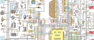
Connection diagram for generator in VAZ cars
The generator in cars is designed to generate electricity and charge the battery. If the normal operation of a car electric generator is disrupted, the battery begins to discharge and soon the car will stop starting completely - there is not enough battery charge. This device consists of a three-phase diode bridge, which, in turn, has 6 silicon diodes. Electrical voltage is created by the excitation of the rectifier at the moment when the rotor poles change under the stator windings. When the rotor rotates inside the machine stator, the poles of the rotor change. To increase the value of magnetic fluxes, the stator contains an electromagnetic exciting winding in the area of the magnetic cores. Marking and designation of wires:
- P - pink.
- F - purple.
- O - orange.
- B&W - black and white.
- KB - brown and white.
- CHG - black and blue.
- K - brown.
- H - black.
- B - white.
Repair costs
The approximate cost of spare parts is shown in the table.
| Name | Price, rub |
| Price of a set of bearing elements | Around 150 rubles. |
| Generator diode bridge | 200 rub. |
| Charging relay | About 150-200 rub. |
| Removal tool for bearing elements | Around 100-200 rubles. |
| Prices are relevant for three regions: Moscow, Chelyabinsk, Krasnodar. | |
Connection diagram for the VAZ-2101 generator
Structurally, generator 2101 consists of the following main elements:
- The rotor is a moving part that rotates from the engine crankshaft. Has an excitation winding.
- The stator is the stationary part of the generator and also has a winding.
- Front and rear covers , inside of which bearings are installed. They have eyelets for attaching to the internal combustion engine. The back cover contains a capacitor necessary to cut off the alternating current component.
- Semiconductor bridge - called a “horseshoe” for its similarity. Three pairs of semiconductor power diodes are mounted on a horseshoe-shaped base.
- A pulley on which the VAZ-2101 generator belt is placed. The belt is V-shaped (on modern cars a multi-ribbed belt is used).
- The voltage regulator is installed in the engine compartment, away from the generator. But still it must be considered part of the structure.
- The brushes are mounted inside the generator and transmit the supply voltage to the field winding (on the rotor).
Connection diagram for the VAZ-2107 generator
1 - battery; 2 - negative diode; 3 - additional diode; 4 - generator; 5 - positive diode; 6 - stator winding; 7 - voltage regulator; 8 — rotor winding; 9 — capacitor for suppressing radio interference; 10 — mounting block; 11 — battery charge indicator lamp in the instrument cluster; 12 - voltmeter; 13 — ignition relay; 14 - ignition switch.
Precautionary measures
The voltage required to activate the generator when the ignition is on is supplied to its positive contact, having previously been connected to the control indicator. After the motor is fully started, the winding receives current from three rectifier diodes.
- The positive output of the battery must be in contact with the positive output of the generator, and the wire from the negative terminal must be connected to ground. Under no circumstances should mistakes be made, as this will entail a sharp increase in current, which will lead to damage to the generator valves.
- It is not allowed to operate the generator with the battery disconnected. Short overvoltages will damage the generator relay and electrical appliances of the vehicle network.
- It is prohibited to test the generator with electronic measuring instruments with a voltage higher than 12V. Sometimes it is necessary to check the stator windings with such devices. This can only be done with the generator disconnected.
- During welding work on the car body, all wires and contacts of the generator must be disconnected
Connection diagram for the VAZ-2108 generator
The VAZ-2108 generator has a rather massive stator winding, since it uses a large cross-section wire. It is with its help that electricity is generated. The wire is wound evenly over the entire inner surface of the stator into recesses specially provided for this purpose in the magnetic core. It’s worth talking about the latter separately. The middle part, the generator stator, consists of a series of thin metal plates pressed tightly together. They are often boiled on the outside to prevent separation.
Connection diagram for the VAZ-2109 generator
- Alternator. The 37.3701 or 94.3701 series can be installed.
- Negative diode.
- Additional diode.
- Positive diode.
- Alternator warning lamp, also known as battery discharge lamp.
- Instrument cluster.
- Voltmeter.
- Relay and fuse box located in the engine compartment in the compartment between the engine and the vehicle interior.
- Additional resistors built into the fuse mounting block.
- Ignition relay.
- Egnition lock.
- Accumulator battery.
- Capacitor.
- Rotor winding.
- The voltage relay is located in the engine compartment.
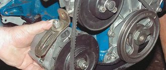
Removing the generator on the “eight”
To dismantle the unit for replacement or repair, you will need “17” keys and a mounting blade. Before starting work, be sure to generously treat all threaded connections to facilitate dismantling. The procedure looks like this:
- Disconnect the negative terminal from the battery.
- Unscrew the top nut securing the generator housing to the bracket.
- Unscrew the nut on the lower mounting bolt.
- Slide the generator housing towards the engine block and remove the belt.
- Unscrew the nut from the power contact and move the wires to the side.
- Remove the lower mounting bolt.
After all these manipulations, you can completely dismantle the unit. This can be done either from below, if protection is not installed on the car, or from above.
Connection diagram for the VAZ-2110 generator
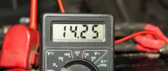
On VAZ-2110, 2111 and 2112 cars, a 94.3701 generator was installed with a maximum output current of 80 Amperes and a voltage = 13.2–14.7 Volts.
Here is a breakdown of the connection diagram for the generator on the ten :
- Battery 12V;
- generator 94.3701;
- mounting block;
- egnition lock;
- battery charge indicator lamp in the instrument cluster
Rotor and stator windings
First, it’s worth talking about what a stator winding is. It is from it that the voltage is removed to power the vehicle’s on-board network and charge the battery. On a VAZ-2109 car, the generator is very similar to an AC asynchronous motor. However, if you make minor changes to the design, the generator can also be used as an electric drive. Three windings on the rotor, each with a beginning and an end. The ends are connected at a common point. This connection is called a “star”.
As for the rotor winding, it is much simpler. There are no extra taps, the copper wire is wound in bulk on the rotor. The ends of the winding are connected to contacts that are located on the back of the rotor
Particular attention, of course, is paid to the magnetic circuit, due to which the field is formed around the coil. When rotating, the magnetic field induces a certain potential in the stator windings
Actually, this is what the entire operation of the generator is based on. But there are many smaller nuances that we can talk about for as long as we like.
How to check the generator yourself
How to check a VAZ generator using the example of model 2109. Generator type 94.3701 alternating current, three-phase, with a built-in rectifier unit and an electronic voltage regulator, right-hand rotation.
Generator connection diagram . The voltage to excite the generator when the ignition is turned on is supplied to terminal “D+” of the regulator (terminal “D” of the generator) through indicator lamp 4 located in the instrument cluster. After starting the engine, the excitation winding is powered by three additional diodes installed on the generator rectifier block. The operation of the generator is controlled by a warning lamp in the instrument cluster. When the ignition is turned on, the lamp should be on, and after starting the engine, it should go out if the generator is working. If the lamp is brightly lit or glows half-lit, it indicates a malfunction.
The “minus” of the battery should always be connected to ground, and the “plus” should always be connected to the “B+” terminal of the generator. Failure to turn the battery back on will immediately cause increased current through the generator valves and damage them.
It is not allowed to operate the generator with the battery disconnected. This will cause short-term overvoltages to occur at the “B+” terminal of the generator, which can damage the generator voltage regulator and electronic devices in the vehicle’s on-board network.
It is prohibited to check the functionality of the generator “for spark” even by briefly connecting the “B+” terminal of the generator to ground. In this case, significant current flows through the valves and they are damaged.
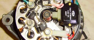
Design Features
VAZ 2109 cars can be equipped with two models of generator units. These are 37.3701 and 9402.3701.
Description of the structural elements of the first:
- 1 — clamping fitting;
- 2 - bushing;
- 3 - buffer fitting;
- 4 — rear cover of the unit;
- 5 - bolt fixing the rectifier device;
- 6 - the rectifier unit itself;
- 7 - valve of this device;
- 8 - capacitor component;
- 9 — rear bearing element of the rotor shaft;
- 10 — slip rings;
- 11 — pulley of the rotor device;
- 12 - brush connected to terminal B of the regulator;
- 13 — contact 30, necessary for connecting energy consumers;
- 14 — contact element 61 of the generating set;
- 15 - brush connected to output Ш on the control mechanism;
- 16 - contact B of this element;
- 17 — the voltage regulator itself in the on-board network;
- 18 — pin for fixing the generating set to the tension bar;
- 19 — impeller;
- 20 - shaft;
- 21 — washers for fixing the bearing device;
- 22 - thrust ring;
- 23 — front bearing element of the rotor device pulley;
- 24 — rotor winding;
- 25 - pole piece of this device;
- 26 - another winding;
- 27 — stator mechanism;
- 28 — front cover of the generator unit.
Diagram of device model 37.3701
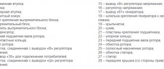
Design of unit 9402.3701:
- 1 — protective casing of the device;
- 2 — contact B+ for connecting the electrical equipment of the machine;
- 3 - capacitor device;
- 4 - common contact of additional diode elements. It connects to the D+ output on the control fixture;
- 5 — fixing device for positive diodes of the rectifying mechanism;
- 6 — clamp for negative diode elements;
- 7 - positive diode;
- 8 - negative element;
- 9 — voltage regulator in the machine’s electrical network;
- 10 — rear cover of the generating set;
- 11 — coupling bolt;
- 12 — front cover of the generating set;
- 13 - stator winding;
- 14 - thrust ring;
- 15 — front bearing element of the rotor mechanism shaft;
- 16 - shaft;
- 17 - nut;
- 18 — shaft of the rotor mechanism;
- 19 — cone-shaped washer;
- 20 - regular washer;
- 21 — pole pieces of the rotor mechanism;
- 22 — core of the stator device;
- 23 - bushing;
- 24 — winding of the rotor mechanism;
- 25 — rear bearing element of the rotor pulley;
- 26 — bushing of the bearing element;
- 27 — slip rings;
- 28 — brush assembly holder;
- 29 — contacts of the stator mechanism winding;
- 30 - additional diode element;
- 31 - common contact D.
Design of the generator 9402.3701
Carburetor power units are equipped with devices model 37.3701, and injectors - 9402.3701. These units are similar in design; they are synchronous AC motors. They are equipped with a built-in rectifier unit based on silicon diode elements. And the voltage regulator in them is electronic.
On vehicles built before 1996, 37.3701 models used separate adjusters and brush holders. In such devices, the voltage from pin 30 was supplied to pin B. In later versions, this parameter is supplied to pin B, since B is absent.
Replacement and removal of the electric generator
The generator on a VAZ car is removed either for complete replacement in case of failure or to carry out repair work to replace faulty parts. To perform dismantling, prepare a standard set of tools; it is advisable to drive the car into the inspection hole.
- Disconnect the battery.
- Remove the protective rubber cap from terminal “30” and unscrew the nut and remove it from the wire stud.
- Disconnect the block with wires from the generator connector.
- We loosen the tightening of the generator to the adjusting bar, then lift it all the way up to the cylinder block and remove the belt from the pulleys.
- Completely unscrew the bolt securing the adjusting bar to the cylinder block, then from the bottom of the car unscrew the 2 bolts securing the lower bracket to the block and remove the generator, pulling it out of the engine compartment.
Source
Safety precautions when working
Nuances that must be taken into account when repairing a VAZ 2109 generator:
- All control and adjustment work related to diagnosing the unit with the engine running must be carried out in a ventilated area or outdoors. If it is a garage, it is recommended to open the doors or provide good ventilation.
- Before carrying out the task, you need to button up your sleeves if the work is performed in a shirt. All hanging ends of clothing should be removed to prevent them from getting caught on the operating pulley.
- To carry out repairs, a specialized tool is used.
- The generator must not be allowed to fall after it has been removed during transportation to the machine. This can lead to complete failure of the unit.
- Repairs should only be carried out using serviceable, clean and oil-free tools.
- If the nuts are rusty and difficult to unscrew, it is recommended to treat the elements with kerosene or WD-40 before turning them out. Dismantling is carried out with preliminary tapping with light blows of a hammer.
- The vehicle is inspected using a 36-volt light bulb. If the diagnosis is performed in a ditch, a 12 V light source will be required. It is important that the light bulb is equipped with a safety net.
Exciting the generator (LADA Samara and similar)
To answer the question briefly, is it possible to provide excitation from a battery , then yes, it is possible, but through a diode.
In details . If the generator excitation suddenly disappears, then you can supply voltage from the battery to input D of the generator during or immediately after starting the engine. Soon, a working generator should switch to self-excitation mode from the voltage it generates. You need to connect through a diode, but not directly, otherwise you risk burning out the generator's additional diodes. And of course, only with the ignition on, otherwise you will drain the battery while parked.
Now in more detail. By itself, simply by rotating the rotor, the generator will not generate voltage. In order for it to start doing this, it needs to be excited - “kicked”, and for this it has an excitation winding that consumes some current. Voltage is supplied to it through contact D of the generator and the voltage regulator. The regulator also turns off the winding when the generated voltage is exceeded, in fact, this is its entire function. There are 2 power modes for the excitation winding. Starting, when the engine starts; and working, when the generator is already running. In the first case, power is supplied to the winding from the battery through a charge control lamp and a diode connected in series with it. In the second case, when the generator begins to generate voltage, the winding is powered through its 3 additional diodes - autonomously.
It happens that the generator does not want to be excited. The very first and simplest possible option here is to check the terminal on contact D of the generator, there may be a bad contact there, everything is very simple: tighten it up, clean it, and be happy. Another option: the charge control lamp has burned out. Naturally, it can be replaced. But if there is no way to change it now, on the road, for example, there are the following options: - “turn on the gas”, and it is likely that the generator will be excited due to residual magnetization; — apply voltage to the excitation winding artificially, i.e. separate wire from the battery. Let's talk about the last method.
Undercharge from the generator. (legendary photo of the instrument panel board here!!!) | Topic started by: Bozidara
Lada 07 injector. I just can’t solve the problem with the generator, I changed the brushes, the diode bridge twice, tightened the belt with a crowbar, and even bought a new generator... Right now the charging is normal, but often the voltmeter goes into the white zone with the headlights off, then again shows normal. Antifreeze wets the generator. What's the matter? Antifreeze or something else, maybe a short somewhere? I can’t find where the antifreeze might be dripping from? Dmitry (Pula) maybe the sensor on the dash is just nonsense Sergey (Kahakuloa) maybe drops of antifreeze from the lower radiator hose are blown onto the generator by the headwind! I just coated all the hoses with sealant! Alexey (Halima) That's it, today I soldered the instrument panel board! Most likely the reason for the undercharging was in the board; the voltmeter needle now constantly stays at the end of the green zone. On the board, the contacts of the chip are not soldered, but simply on rivets, so the contact is bad, I realized this when I changed the headlight indicator lamp, the voltage to the lamps appeared and disappeared when I moved the chip, and it is known that if the battery lamp does not light, there will be no charging from the generator. When you drive, the chip moves due to vibrations, so the charge appears and then disappears.. Andrey (Manuelita) Alexey, that is, because of this chip, charging happened every other time or something???????? Alexey (Halima) Andrey, the lamp in the instrument panel is in the excitation circuit of the generator winding. No contact (or the lamp has burned out) - no charging. It’s convenient to learn the hardware here https://car-exotic.com/vaz-cars/vaz-lada-2107-auto-rep.. Dimka (Ballou) The same crap happened with the board and bad charging)))) I forgot how I soldered it problem, I've been driving for three years now, everything is fine))) Andrey (Manuelita) Dimka, well guys, I'll go take off the panel now, maybe there really is something there Konstantin (Hosain) Is it the board? Shit, I really wanted to torture the generator. The headlights are not on, and the low beams can turn off; you move the button and they light up again. Charging is also somewhat weak. This is the last time the check light came on, the charge dropped to zero, and the gene malfunction light did not turn on (although it works when the ignition is on). In short, I got home on the battery and did not start again (( Alexey (Halima) Konstantin, many not only “torment" generator, but they also go broke on a new one. And all because they are too lazy to learn the hardware, there is nowhere to read, there is no desire... Dmitry (Pula) Guys, the problem is that the charge was measured with a multimeter, everything is fine, but on the dashboard the battery lamp is dimly lit and on the voltmeter at the beginning of the green zone. Everything would be fine, I drive like this for more than six months, it’s annoying, it just doesn’t betray my peace of mind, how can I fix it, where should I go? Alexey (Halima) Dmitry, 1. It’s completely unclear what you measured with a multimeter, if the arrow of the on-board voltage indicator is at the beginning of the green zone, and you write that "everything is fine." 2. For what reason did you not write about the results of replacing the RR, diode bridge, checking all connections, terminals, etc.? 3. If the charge is still enough and you drive like this for more than six months, then you drive on two phases . Repair the generator. The problem has been described here more than once - go to the car. Good luck to you in your work. Dmitry (Pula) Alexey, 13.2, 13.4 showed with a load. I understand thanks Alexey (Halima) Dmitry, this is normal. Try changing the diode bridge. Dmitry (Pula) Thank you, the problem has been fixed Alexey (Halima) Dmitry, on the Internet on forums, etc. In VK groups it is customary to describe the process of solving a problem. SO that those who have a similar problem can do the same. Dmitry (Pula) Alexey, I changed the diode bridge and at the same time the brushes since the output was decent so as not to climb there again. Dmitry (Pula) By the way, I managed to burn the PP, two wires are screwed onto a stud when I pulled it in, I didn’t notice that the terminal touched the fastening bolt, I still got off easy Ilya (Jaskaran) My charging light does not light up when I turn on the ignition, changing the light bulb is of no use. But although charging is going on. Alexey (Halima) Ilya, why isn’t it on? Why is it going? Tell me in detail. Tags:
Where do the wires go from the VAZ 2110 generator
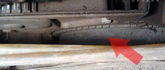
Excitation wire for generator VAZ 2109
It so happened that the battery charge died on the way. In the evening the traffic jam drained all the charge. Using the test method, the cause was determined - the voltage on the gene excitation wire when the ignition is on is 6.5V, which is clearly not enough to excite the generator normally. After lighting the cigarette, charging did not appear. 12V was supplied to pin 61 genes (thin wire) directly from the adjacent wires coming from the battery. Oh miracle! charging appeared - the car started working with the battery disconnected. That is, the problem is clearly not in the gene.
Question No. 1 – Who had this and how was it treated? Suspicions about tidy or CY. Is it really possible to fix it yourself or is it easier to give it to a competent electrician?
Question No. 2 – Is it normal that a working generator is not able to revive a dead battery? I idled the engine at 2.5-3000 rpm for about 20 minutes, but the battery was still not charged and I couldn’t start it myself.
Question No. 3 – Does anyone know a competent electrician in the Golyanovo area?
Etta. was the lamp not on?
If not, then there was enough power from the additional excitation diodes, so this is not the problem. After checking the bridge and regulator, you should think about a complete disassembly with troubleshooting (what is the mileage?)
Everything is real, a matter of desire and time