VAZ 2115 and 2114 cars are equipped with modern equipment that allows you to monitor the serviceability of all systems and units of these brands. To repair temporarily faulty lamps of these models, it is not necessary to go to a service station, but you can acquire a simple tool, and knowledge of where the relay is located to monitor the serviceability of the lamps of a VAZ 2114 and 2115 car, and fix the fault yourself.
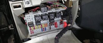
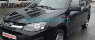
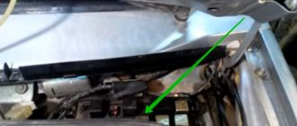
There is a mounting block in the engine compartment of VAZ 2114 and 2115 cars. Its location can be seen in this photo No. 1
VAZ manufacturers have placed in it various relays, as well as fuses, which are responsible for the operation and monitoring of the serviceability of not only lighting devices, dimensions, car turns, interior lighting, as well as windshield wipers.
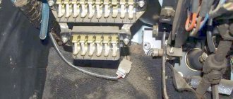
In order to open this mounting block, you need to disconnect two clamps from it, as shown in the photo, and remove the special safety cover. This can be done using pliers or other devices, but it is better not to damage these clamps.
Photo 2
If it is necessary to repair or replace some parts (for example, fuses), then it is better to disconnect the unit itself from the current. To do this, it is disconnected from the battery, that is, the terminals are removed, and then it must be disconnected from the wires connected to it. They are located in a special plug, which is easily separated from the unit itself. Only after this can repairs be made.
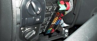
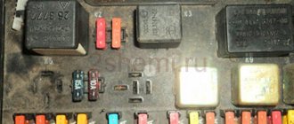
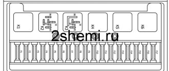
After these manipulations, the VAZ owner will see fuses that have special designations, as well as several relays, and those that are responsible for monitoring the serviceability of the lamps of the VAZ car. If the car has technical documentation, then in the figure these relays for monitoring the health of the lamps will have a special designation. When technical documentation is missing for some reason, then you need to carefully look at the provided photo.
Photo No. 3
On it, these relays are designated as follows:
- K4, it is responsible for the serviceability of the brake light indicator lamps, as well as the vehicle’s side lights;
- K8 is responsible for the proper operation of the car’s high beam lamps;
- K9 is responsible for the proper operation of turning on the low beam lamps of the car.
So if problems arise, the driver must know which relay is responsible for what. They have special designations, as indicated in photo No. 3.
Also in this mounting block there are fuses that are responsible for the functions of VAZ lamps, and have a resistance designed for a certain current strength, and in the event of overvoltage or a technical malfunction, they give a signal to the relay, which, in turn, outputs it to the dashboard.
The location of this block on the above car models does not change, but in some modifications or years of production, the location of the fuses and the relays themselves, which are responsible for performing certain control functions, may be changed. It is from this block that all the signals go to the dashboard, which inform the driver about a particular malfunction of the car’s light bulbs.
It is important to know that some cars are not equipped with such relays. But if you look closely and disassemble the dashboard, you can find an additional wire leading from the mounting block, where, at the request of the car owner, you can install the relay yourself. After such installation, a light signal will appear on the dashboard, which will indicate a malfunction of the lighting equipment.
Search principle
To find a fault in any vehicle on-board network system, you should use the method of sequential elimination of elements. The point is to consistently check electrical appliances and sections of the circuit, excluding elements from the list of reasons that could cause a breakdown. To do this, you need to clearly understand the design and operating principle of the system. When troubleshooting, you need to move from the components that require the least effort to check, to the most difficult to diagnose elements.
Electrical diagram
We immediately emphasize that the pinout of connectors and color markings of wires may differ not only between different models of the same automaker, but also among one model of different years of manufacture. Before you start searching for the cause of the breakdown, you need to find an electrical diagram specifically for your car model.
We will consider the principle of operation of brake lights and the troubleshooting algorithm using the example of the VAZ 2101-2102 circuit. The photo shows the general diagram of the vehicle's lighting and light signaling. We need to isolate the components involved in the operation of brake lights.
- 6 – mounting fuse block;
- 13 – brake light switch. It is a non-locking button (returns to its original position after removing the force). Located directly next to the brake pedal. When the brake pedal is released, the contacts of the limit switch are open, no current passes through it. Accordingly, when pressed, the contacts close, allowing flow through the lamps;
- 19 – lamps that light up when you press the brake pedal.
We do not have a diagram of the mounting block, but we know in advance that the brake lights only work when the ignition is on. There is a wire from the mounting block to the brake light limit switch, on which there is a constant + after the ignition is turned on. As soon as the limit switch contacts close, + goes to the brake light bulbs, which are connected in parallel. The “ground” of the rear lights is common and consists of a wire screwed to the car body.
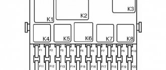
In the diagram we presented, the elements are depicted as close as possible to how they look in reality. Don’t be alarmed if you only find a schematic diagram for your car with symbolic images of the elements. Schematic diagram of external lighting for VAZ 2114, 2115:
- 3 – mounting block;
- 8 – lamps for side lights and brake lights;
- 11 – brake light limit switch;
- K4 – relay for monitoring the serviceability of brake light lamps and side lights.
Limitations and procedure for modifying the turn relay
Installation of LEDs is possible only if the relays are digital. For cars of the VAZ or GAZ family, these are devices marked with the designation 494.3747 (for comparison: the designation for analog ones is 231.3747). When there is no marking, the relay class is quite simply determined by its dimensions, which are noticeably larger for the analog version. If the car only operates analog, you will have to purchase a digital one.
Appearance of digital and analog turn relays
The direction indicator is modified in the following sequence:
- The case is opened;
- The location of the chip responsible for the operation of the turn signals is determined: it is usually located to the right of the external board.
- The capacitor is replaced, which determines the frequency of the turn signal lamp blinking generator. The subtlety is that the capacitor capacity should be within 4.7 µF at 50 V operating voltage. Alternatively, you can install another capacitor; in most cases, the space inside the relay case allows this operation.
- Output parameters are monitored using measuring instruments. If the LEDs are functioning properly, the housing is installed in its original place.
As additional items you should purchase:
- P-channel transistor;
- A resistor from the above resistance range (if it will be soldered into the circuit and not a capacitor);
- LEDs (preferably red or orange).
Soldering of such a modernized version of the relay can be done using the usual hinged method, on top of the main circuit.
Fault localization
Understanding the operating principle allows you to determine exactly why the brake lights may not light up:
The fuse has blown. In the diagram, the fuses are marked with the letter F (from English - Fuse) and the serial number of the seat in the fuse block, for example, F3;- poor contact at connectors;
- the light bulbs have burned out, but since the lights are connected in parallel, the likelihood that 2 lamps will burn out at once is extremely low;
- poor contact on the negative terminal of the lights. In this case, problems may begin not only with the feet, but also with the lighting of the remaining lamps in the lanterns;
- Damage to the negative track in the lamp board. From the total mass directly to the brake light lamp, the minus goes along a special path on the board. The path may collapse from water or mechanical impact;
- malfunction of the brake light switch, the so-called frog;
- broken wiring, oxidation of contacts.
How to troubleshoot?
The most common reasons that the brake light on the VAZ 2114 does not work are the following factors:
- Fuse failure.
- Broken wires in one of the sections of the circuit.
- Limit switch faulty.
- Bulbs burn out.
- Oxidation of contacts in lamp sockets.
- Damage to the contact board.
The most common and at the same time the most easily removable of the above reasons is a blown fuse. To identify such a malfunction, you need to examine the fuse box. A 10-amp fuse F3 is responsible for the brake lights, which also protects the ignition switch, computer and interior lighting.
Malfunctions in the operation of the latter may also indicate a malfunction of the stop fuse (and in this case, troubleshooting should begin with the block). If it turns out that the fuse has blown, then you should replace it with a new, similar one.
A new fuse installed in place of a failed one must be designed for exactly the same maximum current. If it is less, the fuses will blow more often, and if it is more, the protected device itself may burn out.
The problem may also be in the fuse block itself - sometimes the tracks on its printed circuit boards burn out or the contact legs oxidize. In order to check its serviceability, it is enough to measure the voltage at the contacts of the newly installed fuse.
Car electrical equipment
The electrical equipment of a car (another name is the electrical system of a car) is designed to generate electrical energy and power various systems and devices of the car.
The electrical equipment of a car combines current sources and consumers, controls, and electrical wiring. All structural elements of electrical equipment are integrated into the on-board network.
The sources of current in a car are the battery and the generator.
The battery is designed to supply consumers with electric current when the engine is not running, when the engine is started, and when the engine is running at low speeds.
The main source of electric current is the generator. It provides electrical power to all consumers, as well as charging the battery.
The capacity of the battery and the power of the generator must correspond to the power of electricity consumers in all operating modes of the vehicle, i.e. Energy balance must be maintained in the system.
Energy consumers can be divided into three groups: main, long-term and short-term. The main energy consumers ensure the vehicle's performance. These include: fuel system, injection system, ignition system, engine management system, automatic transmission, electric power steering.
Long-term consumers are the cooling system, lighting system, active safety systems, passive safety systems, heating and air conditioning systems, anti-theft systems, audio systems, navigation systems.
Short-term consumers include most comfort systems, starting system, glow plugs, horn, cigarette lighter.
Control elements ensure coordinated operation of current sources and electricity consumers. The system uses the following control elements: fuse panels, relay blocks, electronic control units. They are located, as a rule, decentralized.
On modern cars, many functions of relays and switches are assigned to electronic control units, but it is not yet possible to completely abandon these devices. For example, the on-board network control unit is assigned the following functions:
- energy consumption control;
- monitoring the voltage at the battery terminals and, if necessary, increasing the engine speed at idle;
- load regulation by disconnecting individual consumers, mainly from comfort systems;
- control of the lighting system, windshield wipers, rear window heater, etc.
In addition to traditional electrical wiring, the vehicle's on-board network uses multiplex systems - the so-called. data buses that ensure the connection of electronic control units with each other and the transmission of control signals in digital form.
Malfunction of the lights themselves
If during the check from the fuse box to the limit switch no problems are found, then you should move on. Now you should test the wiring from the second limit switch connector to the stop connectors with a tester. If it is working, then you need to check the board. The printed circuit board on which the taillights are mounted is not ideal, and is one of the biggest problems of all VAZ cars.
Its tracks often burn out or peel off, causing the lights to stop working. This problem can be solved in two ways - either re-solder the tracks (which can be done with a regular soldering iron, although not in road conditions) or replace the board with a new one (most motorists choose the second option).
Another reason why the VAZ 2114 brake lights do not work may be oxidation of the lamp sockets. In order to eliminate this problem, it is enough to clean all contacts from oxides that have appeared on them.
This is best done in one of the following ways:
- small grit sandpaper;
- WD-40 solution;
- kerosene;
- purified gasoline (“galosh”).
You should absolutely not use gasoline or other solvents to clean contacts.
The last option for faulty stops is the light bulbs themselves. It makes no sense to give any detailed advice here - you just need to replace the burnt out light bulbs with new ones.
By following all the tips listed above, the car enthusiast gets the opportunity to check the entire electrical circuit of the brake lights, starting from the fuse box and ending with the bulbs in the lamps. Thanks to this, the guarantee that the fault will be accurately detected and eliminated is 100%.
New mounting block
The turn signal relay is an electromagnetic device responsible for turning on and blinking the turn signal lights.
The turn signal relay is located in the mounting block under the hood in a plastic case. This device is marked with the letter K2, or a conventional symbol in the form of a triangle. There is also a fuse that protects the electrical circuit from burnout. It is located in the left lane, second in a row.
Additional Tips
Before each trip, especially over long distances, you should check the functionality of all lighting equipment, including brake lights. In order to reduce the likelihood of breakdowns along the way, you need to periodically check the condition of the sockets and bases of the rear light bulbs, and periodically clean them of oxides and dirt.
In case a breakdown does occur, you should always have an additional set of light bulbs and 10 amp fuses in your car, as well as a multimeter to check them.
Use the second wrench as leverage
If you are trying to unscrew a stuck/rusted/oxidized bolt or nut and are unsuccessful, stop for a second and remember Archimedes, who said the great phrase: “Give me a fulcrum and I will move the Earth.” This means that the task is simplified. Remember, the torque required to remove a bolt or nut is equal to the force times the distance. So why go out of your way to increase “power” when you can simply increase “distance”?
Take the second wrench and put it on as shown in the photo. That is, put it on the end of the first key to get one large lever. We twist the bolt/nut, but try not to overdo it.