To ensure maintenance and repair of the electrical equipment of a VAZ car, a special approach was taken to the layout of each of the components of the overall system. That is, all relays and fuses were placed in one compact housing of the mounting block. The use of switching interconnected circuits of various electrical equipment systems makes it possible to avoid installing a large number of relays throughout the machine body and simplifies the process of repairing parts to replace them. To find faulty elements, you do not need to disassemble the entire car - you just need to replace the device itself, which is connected to the circuit using standardized connectors. Diagnostic connectors help us with this. Below are the electrical circuit diagrams of the MB for a VAZ car.
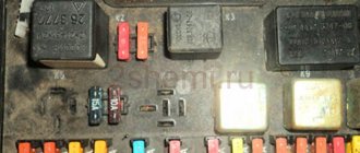
Pinout of mounting block 2107
Circuits protected by fuses
| Fuse no. | Protected Circuits |
| F1 (8A)(10A) | Rear lights (reversing light). Heater motor. Warning lamp and rear window heating relay (winding) |
| F2 (8A)(10A) | Windshield wiper and washer motors. Headlight wiper and washer motors. Windshield wiper relay. Headlight wiper and washer relay (contacts) |
| F3 (8A)(10A) | Spare |
| F4 (8A)(10A) | Spare |
| F5 (16A)(20A) | Rear window heating element and heating relay (contacts) |
| F6 (8A)(10A) | Cigarette lighter. Socket for portable lamp |
| F7 (16A)(20A) | Horns and horn relays |
| F8 (8A)(10A) | Direction indicators in hazard warning mode. Switch and relay-breaker for direction indicators and hazard warning lights in hazard warning mode |
| F9 (8A)(10A) | Generator voltage regulator (for vehicles with generator G-222) |
| F10 (8A)(10A) | Direction indicators in turn indication mode and the corresponding warning lamp. Relay for turning on the fan motor (winding). Indicator lamp for fuel reserve, oil pressure, parking brake, brake fluid level. Indicator lamp for battery charge. Instrument cluster. Voltmeter. Carburetor electro-pneumatic valve control system. Parking brake warning lamp relay-breaker |
| F11 (8A)(10A) | Rear lights (brake lamps). Internal body light |
| F12 (8A)(10A) | Right headlight (high beam). Coil of the relay for turning on the headlight cleaners (with the high beam on) |
| F13 (8A)(10A) | Left headlight (high beam). High beam indicator lamp |
| F14 (8A)(10A) | Left headlight (side light). Right rear light (side light). License plate lights. Engine compartment lamp. Indicator lamp for side lighting |
| F15 (8A)(10A) | Right headlight (side light). Left rear light (side light). Cigarette lighter lamp. Instrument lighting lamps. Glove box lighting lamp |
| F16 (8A)(10A) | Right headlight (low beam). Coil of the relay for turning on the headlight cleaners (with the low beam on) |
| F17 (8A)(10A) | Left headlight (low beam) |
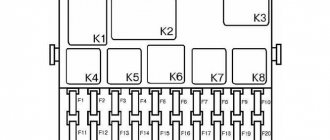
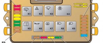
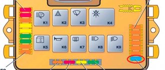
Mounting block diagram 2105-3722010-02
LADA 21054, 21074
| K1 | Heated rear window relay |
| K2 | Headlight washer cleaner relay |
| K3 | Horn relay (jumper) |
| K4 | Fan motor relay |
| K5 | High beam relay |
| K6 | Low beam relay |
Circuits protected by fuses
| Fuse no. | Protected Circuits |
| F1 (10A) | Reversing lamps. Heater electric motor. Rear window heating indicator. Rear window heating relay (winding). |
| F2 (10A) | Windshield wiper motors. Windshield washer pump motors. Windshield wiper relay. Relay for cleaners and headlight washers (contacts). |
| F3 (10A) | Spare. |
| F4 (10A) | Spare. |
| F5 (20A) | Rear window heating element. Relay for turning on the heated rear window (contacts). |
| F6 (10A) | Cigarette lighter. Watch. |
| F7 (20A) | Sound signal. Horn relay. Radiator cooling fan electric motor. Radiator cooling fan motor relay (contacts) |
| F8 (10A) | Direction indicators (in hazard warning mode). Turn signal indicator (in hazard warning mode). Relay-breaker for direction indicators and hazard warning lights. Hazard warning switch with warning lamp. |
| F9 (7.5A) | Rear fog lamps. Indicator for switching on the rear fog lamps. |
| F10 (10A) | Direction indicators (in turn indication mode). Turn signal interrupter relay. Turn signal indicator. Tachometer. Fuel indicator. Fuel reserve indicator. Parking brake indicator. Indicator of insufficient oil pressure in the engine lubrication system. Coolant temperature gauge. Voltmeter. Indicator of emergency condition of the working brake system. Battery charge indicator. Electric fan relay. Generator excitation winding (generator 37.3701). |
| F11 (10A) | Interior lighting lamps. Brake light bulbs. Luggage compartment lamps. |
| F12 (10A) | High beam headlights (right headlight). |
| F13 (10A) | High beam headlights (left block headlight). High beam indicator. |
| F14 (10A) | Front side light (left headlight). Rear marker light (right light). License plate lights. Indicator for turning on side lights. |
| F15 (10A) | Front marker light (right headlight). Rear marker light (left light). Cigarette lighter lamp. Instrument lighting lamp. Glove box lighting lamp. Clock (lighting lamp). |
| F16 (10A) | Low beam headlights (right headlight). Headlight cleaner relay (relay coil). |
| F17 (10A) | Low beam headlights (left block headlight). |
What is the purpose of MB?
The electrical circuit of modern cars is quite complex even for experienced auto mechanics. Therefore, in order to ensure its maintenance and repair, a special approach was applied to the layout of each of the components of the overall system. To put it simply, almost all relays and fuses are placed in one compact housing of the mounting block - it is impossible to imagine a modern car without it.
This part is the central module of the car’s electrical equipment, which combines the control and protection of all electrical devices. The use of switching interconnected circuits of various electrical equipment systems makes it possible to avoid installing a large number of relays throughout the machine body and simplifies the process of repairing parts to replace them. There is no need to disassemble the entire car to find faulty elements. If the breakdown is serious, there is no need to arm yourself with a soldering iron. It is enough just to replace the device itself, which is connected to the circuit using standardized connectors.
The mounting block can be called one of the most important devices in the electrical system of a car. Almost the entire electrical circuit of the car converges in the body of the part. If a malfunction is detected, checking the electrical circuits must begin with the unit.
Pinout of mounting block 2108
Here is a new type mounting block. The old-style block generally has the same circuit, but some contacts (less than 5%) may not match.
Schematic electrical diagram of the LADA Samara mounting block (VAZ-21099 with VAZ-2114 panel).
Numbering of terminals in connecting blocks, color of wires and electrical circuits connected to them.
| Connector | Contact | Wire color | Purpose |
| X1 (Ш1) | 1 | B | window lifters |
| 2 | G | ignition switch (cl. 15/2) | |
| 3 | GP | ignition switch (terminal 15) | |
| 4 | ZhG | heater motor switch | |
| 5 | R | ignition switch (cl. 30/1) | |
| 6 | KR | ignition switch (terminal 30) | |
| 7 | door lock | ||
| 8 | P | ignition switch (terminal 50) | |
| X2 (Ш2) | 1 | BG | rear window wiper switch |
| 2 | G | Turn signal switch (right) | |
| 3 | RP | brake light switch | |
| 4 | B | lamp continuity indicator | |
| 5 | IF | hazard warning switch | |
| 6 | GB | left front door | |
| 7 | ABOUT | rear fog light switch | |
| 8 | 34 | high beam warning lamp | |
| 9 | — | ||
| 10 | 4 | rear fog light switch | |
| 11 | sch | fuel reserve warning lamp | |
| 12 | IF | fuel level warning lamp | |
| 13 | Warhead | interior lamp | |
| 14 | KG | hand brake warning lamp | |
| 15 | hh | Turn signal switch (left) | |
| 16 | electric motor for headlight cleaner | ||
| 17 | — | ||
| X3 (Ш3) | 1 | and | speed sensor |
| 2 | emergency | hazard warning switch | |
| 3 | GP | direction indicator switch | |
| 4 | SB | oil level warning lamp | |
| 5 | H | weight | |
| 6 | RB | washer fluid level warning lamp | |
| 7 | RO | brake lining wear warning lamp | |
| 8 | 3 in | headlight switch | |
| 9 | ZhZ | windshield wiper switch | |
| 10 | PG | portable lamp connection socket | |
| 11 | ignition switch (terminal 15) | ||
| 12 | RF | rear window washer switch | |
| 13 | |||
| 14 | and | fog light warning lamp | |
| 15 | |||
| 16 | SG | oil pressure indicator | |
| 17 | |||
| 18 | R | wiper switch | |
| 19 | CO | wiper switch | |
| 20 | WITH | wiper switch | |
| 21 | ABOUT | rear fog light switch | |
| X4 (Ш4) | 1 | Salary | On and indicator lamp for heated rear window |
| 2 | GB | headlight switch (high beam) | |
| 3 | ABOUT | wiper | |
| 4 | Warhead | outdoor lighting switch | |
| 5 | TO | Instrument lighting rheostat | |
| 6 | R | battery | |
| 7 | BW | windshield wiper and washer switch | |
| 8 | ABOUT | block Ш4 of the mounting block terminal 3 | |
| 9 | midrange | horn switch | |
| 10 | BP | brake light switch | |
| 11 | R | battery | |
| 12 | JV | headlight switch (low beam) | |
| 13 | warning light | ||
| 14 | — | ||
| 15 | — | ||
| 16 | RG | brake fluid level warning lamp | |
| 17 | ZB | coolant temperature gauge | |
| 18 | KB | battery charge indicator lamp | |
| 19 | ZhCh | fog light switch | |
| 20 | RZ | coolant level warning lamp | |
| 21 | AND | tachometer | |
| X5 (W5) | 1 | 3 | high beam (right) |
| 2 | 3H | high beam (left) | |
| 3 | midrange | low beam (left) | |
| 4 | P | starter (cl. 50) | |
| 5 | PB | electric radiator cooling fan | |
| 6 | WITH | low beam (right) | |
| X6 (Ш6) | 1 | — | |
| 2 | 3 | reverse light switch | |
| 3 | MS | Turn signal (left front) | |
| 4 | — | ||
| 5 | — | ||
| 6 | — | ||
| 7 | — | ||
| 8 | ZhCh | side light (right front) | |
| 9 | Warhead | electric fan thermostat | |
| 10 | ZhCh | side light (left front) | |
| 11 | G | Turn signal (right front) | |
| 12 | reverse light switch | ||
| 13 | RG | brake fluid level sensor | |
| X7 (W7) | 1 | — | |
| 2 | ZhG | electric motor for headlight cleaner | |
| 3 | B | electric motor for headlight cleaner | |
| 4 | — | ||
| 5 | SB | oil level sensor | |
| 6 | midrange | sound signals | |
| 7 | WITH | speed sensor | |
| 8 | ZB | coolant temperature sensor | |
| 9 | KB | generator (cl. 61) | |
| 10 | R | windshield washer pump | |
| 11 | Warhead | engine compartment lamp switch | |
| 12 | RB | washer fluid level sensor | |
| 13 | RF | brake linings | |
| 14 | — | ||
| 15 | KP | tachometer | |
| 16 | RZ | coolant level sensor | |
| 17 | reinforced concrete | fog light relay | |
| X8 (W8) | 1 | ZhP | fog light relay |
| 2 | ZhCh | fog lamp (left) | |
| 3 | AND | fog lamp (right) | |
| 4 | GP | ignition coil | |
| 5 | R | generator (cl. 30) | |
| 6 | R | generator (cl. 30) | |
| 7 | — | ||
| S | RF | fog light relay | |
| X9 (W9) | 1 | RF | electric motor rear window wiper |
| 2 | G | Turn signal (right rear) | |
| 3 | BG | electric motor rear window wiper | |
| 4 | VERY | rear fog lights | |
| 5 | midrange | back door | |
| 6 | IF | front right door | |
| 7 | Warhead | interior lamp | |
| 8 | KG | handbrake sensor | |
| 9 | Warhead | open door alarm buttons | |
| 10 | rear window heating elements | ||
| 11 | WITH | license plate light | |
| 12 | GB | front left door | |
| 13 | B | interior lamp | |
| 14 | P | brake lights | |
| 15 | AND | side light (right rear) | |
| 16 | 3 | reversing light | |
| 17 | ZhCh | side light (left rear) | |
| 18 | ZhG | rear window cleaner | |
| 19 | rear window heating elements | ||
| X11 (W11) | 1 | AND | pump |
| 2 | RF | rear window washer valve | |
| 3 | — | ||
| 4 | AND | pump | |
| 5 | Warhead | engine compartment lamp | |
| 6 | — | ||
| 7 | — | ||
| 8 | CC | engine compartment lamp | |
| 9 | B | electric windshield wiper motor | |
| 10 | windshield wiper motor | ||
| 11 | — | ||
| 12 | CO | emergency oil pressure sensor | |
| 13 | — | ||
| 14 | R | windshield washer valve | |
| 15 | CO | electric wiper motor | |
| 16 | WITH | electric windshield wiper motor | |
| 17 | reinforced concrete | electric windshield wiper motor | |
| 18 | — | ||
| 19 | — |
Useful: VAZ tachometer connection diagram
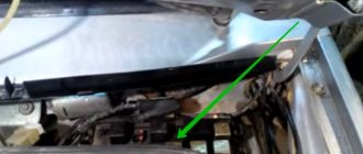
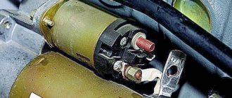
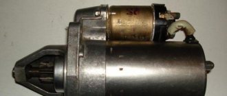
Where is the PTF relay located?
On VAZ 2114 cars there are no front fog lights by default. Installation of PTF is an additional option. On older versions, the fog light relay is installed in the engine compartment. For easy access to it, it is necessary to remove the battery. On modern models, the fog light relay is installed in the passenger compartment. It is located on the driver's side under the steering column.
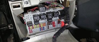
Pinout of mounting block 2109
The VAZ 2109 mounting block is designed to combine wiring harnesses, as well as to accommodate relays and fuses. The first models used a mounting block type 17.3722. It consists of a housing consisting of two parts and a printed circuit board on which leads are soldered for connection to the wiring harness blocks, installation of relays and fuses.
On cars with an injection engine, mounting blocks similar to 2114-3722010-60 are used, but they have a different connection for the radiator cooling fan.
| Fuse no.' | Protected Circuits |
| 1 (8 A) F9 (7.5 A) | Right fog lamp |
| 2 (8 A) F8 (7.5 A) | Left fog lamp |
| 3 (8 A) F1 (10 A) | Headlight cleaners (at the moment of switching on). Relay for turning on headlight cleaners (contacts). Headlight washer activation valve |
| 4 (16 A) F7 (30 A) | Headlight cleaners (in operating mode). Relay for turning on headlight cleaners (winding). Heater fan motor. Window washer motor. Rear window wiper motor. Rear window washer timing relay. Valves for turning on the windshield and rear windows. Relay (winding) for turning on the electric fan of the engine cooling system. Relay (coil) for turning on the heated rear window. Control 'Lamp for heated rear window. Glove compartment lamp |
| 5 (8 A) F16 (15 A) | Direction indicators and relay-interrupter for direction indicators and hazard warning lights (in turn indication mode). Turn signal indicator lamp. Rear lights (reversing lamps). Gearmotor and windshield wiper activation relay. Generator excitation winding (when starting the engine). Brake fluid level warning lamp. Oil pressure warning lamp. Carburetor air damper warning lamp. Parking brake warning lamp. Light display lamp "STOR". Coolant temperature gauge. Fuel level indicator with reserve warning lamp. Voltmeter |
| 6 (8 A) FZ (10 A) | Rear lights (brake lamps). Interior lighting |
| 6(8 A) F6 (30 A) | Power windows for front doors. Power window relay |
| 7 (8 A) F10 (7.5 A) | License plate lights. Engine compartment lamp. Instrument lighting lamps. Indicator lamp for external lighting. Heater lever illumination display. Cigarette lighter lamp |
| 8 (16 A) F5 (20 A) | The electric motor of the engine cooling system fan and its activation relay (contacts). Sound signal and relay for its activation |
| 9 (8 A) F10 (7.5 A) | Left headlight (side light). Left rear light (side light) |
| 10 (8 A) F11 (7.5 A) | Right headlight (side light). Right rear light (side light) |
| 11 (8 A) F2 (10 A) | Direction indicators and hazard warning relay-breaker (in hazard warning mode). Hazard warning lamp |
| 12 (16 A) F4 (20 A) | Rear window heating element. Relay (contacts) for turning on the heated rear window. Plug socket for portable lamp. Cigarette lighter" |
| 13 (8 A) F15 (7.5 A) | Right headlight (high beam) |
| 14 (8 A) F14 (7.5 A) | Left headlight (high beam). Indicator lamp for high beam headlights |
| 15 (8 A) F13 (7.5 A) | Left headlight (low beam) |
| 16 (8 A) F12 (7.5 A) | Right headlight (low beam) |
Replacing fuses on a VAZ 2114
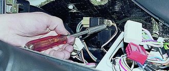
When any problems are detected in the operation of the car’s electrical network and engine, be it the burnout of light bulbs or the failure of some electrical devices, the driver must first check the functionality of the fuses. The procedure is as follows:
- determine where the fuses are located on the VAZ 2114, which may have failed. To do this, look in the machine’s operating manual for a diagram of the location of the protective devices and determine whether they are located in the mounting block or under the dashboard in the area where the front passenger’s feet are located;
- when working with the car's electrical system, the negative contact of the battery must be disconnected;
- open the plastic latches holding the mounting block cover;
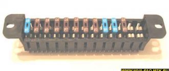
- remove the plastic tweezers from the mount in the upper right part of the block; they can be red, transparent or yellow;
- take the protective device, the circuit of which is supposed to be broken, by the body with tweezers and pull out the fuse;
- There are rules, developed by operating experience, on how to check the fuse. First of all, it is necessary to visually determine whether the fuse-link inside the case has burned out or whether the charger is in good condition;
- if the destruction of the insert cannot be visually determined, it is necessary to check the protective device using a device;
- If confirmation is received that the fuse has blown, it must be replaced with a functional one. The price for a VAZ 2114 fuse box on the automotive market is about 2,000 rubles, and a set of separate chargers of this type will cost 150 -250 rubles.
Attention!
It is strictly forbidden to install home-made devices or jumpers in place of failed chargers, as well as fuses with a different rated insert current. A short circuit or fire may occur.
When working with the mounting block, do not use metal screwdrivers or other metal tools, this can lead to a short circuit and failure of the mounting tracks of the block.
We invite you to watch this useful video:
The article was written thanks to the online information publication https://novyjgod.com/. This is a portal about everything: news, holidays, cars, construction and repairs, gifts, recipes, gadgets, sports, tourism, studies, finance, fashion, society.
Pinout of mounting block 2110
| K1 | Relay for monitoring the health of lamps (contact jumpers are shown inside, which are installed instead of the relay) |
| K2 | Windshield wiper relay |
| K3 | Relay-breaker for direction indicators and hazard warning lights |
| K4 | Low beam relay |
| K5 | High beam relay |
| K6 | Additional relay |
| K7 | Heated rear window relay |
| K8 | Rear Fog Light Relay (Backup Relay) |
Circuits protected by fuses
| Fuse no. | Protected Circuits |
| F1(5A) | License plate light lamps. Instrument lighting lamps. Side light indicator lamp. Trunk light lamp. Left side side light lamps |
| F2(7.5A) | Left headlight (low beam) |
| F3(10A) | Left headlight (high beam) |
| F4(10A) | Right fog lamp |
| F5(30A) | Electric door window motors |
| F6(15A) | portable lamp |
| F7(20A) | Engine cooling fan motor. Sound signal. |
| F8(20A) | Rear window heating element. Relay (contacts) for turning on the rear window heating |
| F9(20A) | Recirculation valve. Cleaners and washers of the windshield, rear window and headlights. Relay (coil) for turning on the heated rear window |
| F10(20A) | Spare |
| F11(5A) | Starboard side marker lamps |
| F12(7.5A) | Right headlight (low beam) |
| F13(10A) | Right headlight (high beam). High beam indicator lamp |
| F14(10A) | Left fog lamp |
| F15(20A) | Electric seat heating. Trunk lock |
| F16(10A) | Relay-breaker for direction indicators and hazard warning lights (in hazard warning mode). Hazard warning lamp |
| F17(7.5A) | Interior lighting lamp. Individual backlight lamp. Ignition switch backlight lamp. Brake light lamps. Clock (or trip computer) |
| F18(25A) | Glove compartment lamp. Heater controller. Cigarette lighter |
| F19(10A) | Door locking. Relay for monitoring the serviceability of brake light and side light lamps. Direction indicators with warning lamps. Reversing light lamps. Generator excitation winding. On-board control system display unit. Instrument cluster. Clock (or trip computer) |
| F20(7.5A) | Rear fog lamps |
VAZ instrument cluster diagram 2110, 2110, 2111, 2112
Device functions
The described part includes more than a dozen electronic keys, which are responsible for starting the starter, monitoring the health of light bulbs, and switching low/high beams. Also, with the help of a relay, the inclusion of fog lights, windshield wipers (with additional switching of their speed), the inclusion of headlight cleaners, power windows, rear window heating and much more is ensured.
True, not every car has all types of relays, since the front seat heating circuit is present only as an additional option. The same situation applies to headlight cleaners, fog lights and much more.
If we talk about fuses, they are responsible for protecting almost all electrical circuits, with the exception of only the power cables through which current is supplied to the engine and the battery is charged. Some devices protect several power supply circuits with the same currents at once, which causes the failure of several systems if just one fuse fails.
Schematic electrical diagrams, connecting devices and pinouts of connectors