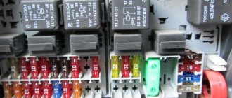
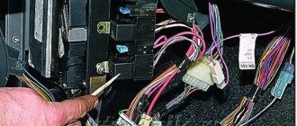
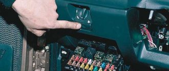
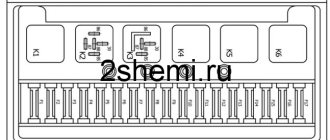
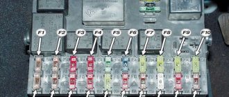
The turn signal fuse on the VAZ 2114 is necessary to protect the wiring from fire when the load is exceeded or a short circuit occurs. Constant burnout of the fuse element indicates a malfunction in the direction indicator circuit. To understand where the turn signal fuse is located on a VAZ 2114, you should dismantle and turn over the block cover. The reverse side shows the designations and locations of relays and fuses. The location of the fusible element may vary depending on the year of manufacture of the vehicle.
New sample block
On newer car models, fuse F 16 . It is located 7th in the right column (from top to bottom).
Its power is 15 amperes. In addition to the direction indicators, the element is responsible for protecting such circuits as:
- Lights when the car is moving in reverse.
- Indicator for turning on/off the parking brake system.
- Low engine oil pressure lamp.
- Generator excitation winding (when starting the power plant).
- Low brake fluid level lamp.
- Instrument cluster.
- Insufficient battery charge lamp.
If the turn signal fuse on a VAZ 2114 blows, all protected consumers stop working at the same time. The occurrence of such a malfunction requires replacement of the fusible element.
Old mounting block
In old-style units, the turn signal fuse is designated F16 . It is installed 5th in a row from left to right .
The maximum fuse capacity is also 15 amperes. Additionally, the element protects the following circuits:
- Lights when the car is moving in reverse.
- Generator excitation winding (when starting the power unit).
- Electric motor and relay for turning on the windshield wiper.
- Voltmeter.
- Low oil pressure lamp.
- Fuel level indicator in the tank.
- Warning lamp for insufficient brake fluid level.
- Parking brake indicator.
- Engine cooling system fluid temperature gauge.
To make it easy to remove the fuse from its seat, the manufacturer provides specialized tweezers. It is installed in the mounting block.
Purpose of the VAZ 2107 relay
| Relay number | Relay purpose |
| R1 | Heated rear window relay |
| R2 | Relay for headlight cleaners and washers (wiper relay) |
| R3 | Signal relay. If there are two signals, then there is a relay. If there is only one signal, a jumper |
| R4 | VAZ 2107 cooling system fan relay. Or a jumper if the car is fuel-injected |
| R5 | High beam relay |
| R6 | Low beam relay |
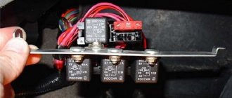
On VAZ 2107 cars with an injection engine, several more relays and fuses can be found under the glove compartment. They look like this:
Do the wipers turn on themselves on the VAZ 2114? Solution
Water and dirt accumulate on the windshield during rain, snow, and dust flows. To get rid of this, the design of the car provides for the presence of special elements - wipers.
Circuit breakers
Inside the cabin, at the driver's fingertips, there is a windshield wiper speed control . Brushes can have different sizes and function in several modes.
If we talk about windshield wipers on the VAZ 2114, they have four operating modes:
- With interruptions;
- At first speed;
- At second speed;
- Together with washer.
There are two modes on the rear window:
- With washer;
- No washer.
Dimensions
In fact, the size of the wipers on the VAZ 2114 plays a fairly large role in the quality and efficiency of glass cleaning.
Windshield wiper wiring diagram
Small brushes are also not good, because then the cleaning area is reduced and not the entire glass surface is cleaned, which would provide the required visibility for the driver.
Then what should be the size of these same brushes in the case of the “fourteenth” model?
- The windshield of the VAZ 2114 has two blades of the same size - 51 centimeters. The brush on the driver's side can be replaced with an element 53 centimeters long, but on the passenger's side it is important to leave 51 cm. Otherwise, a strip of cleaned water will remain on the glass between the driver and passenger.
- There is also a cleaner on the rear window of the VAZ 2114. But in this case, the size of the element is 30 centimeters. It is possible to install the wiper at 33 centimeters, which allows it to fit perfectly into the dimensions of the rear window. Some even install components at 40 centimeters, but in this case you will definitely have to increase the wiper stroke limit. To do this, remove the motor, shift the teeth by several units and put it in place.
Common problems
It is not uncommon for car owners to encounter a situation where the wipers on a VAZ 2114 do not work properly. The causes of the problems may be different, so you should carefully examine the breakdown, and then take appropriate action.
Typical faults include:
- They work constantly;
- The windshield wipers may operate on their own, even though the driver has not turned anything on or pressed anything;
- May work too slowly;
- Spontaneous switching occurs.
Replacing the motor
In practice, replacing wipers on a VAZ 2114 may be necessary in several cases. The most common is the failure of the gear motor.
There are different reasons:
- The brushes constantly work, the shutdown relay does not work;
- Turning on the regulator does not allow the wipers to start;
- Sometimes the windshield wipers simply do not turn off when the corresponding buttons are pressed, etc.
Relay for turn signals, alarm and ignition relay for VAZ 2107
The turn signal and ignition relay is located behind the instrument panel. To replace or check the relay, you need to remove the instrument panel and you can see it behind it:
| Relay number | Relay purpose |
| R4 | Ignition relay VAZ 2107 |
| R5 | Relay for alarm and turn signals VAZ 2107 |
Blocks in the engine compartment
Depending on the year of manufacture of the car and the configuration, there may be one or two blocks in the engine compartment. They are installed between the battery and the upper mount of the left shock absorber strut.
Power block
Power block location
For cars produced in 2007-2013
| Designation on the diagram | Denomination, A | Protected circuit |
| F1 | 50 | Generator power circuit (generator to battery connection) |
| F2 | 50 | Electric power steering |
| F3 | 60 | Generator power circuit (generator to battery connection) |
| F4 | 30 | ABS |
| F5 | 30 | ABS |
| F6 | 30 | Engine control circuits |
For cars produced in 2013-2018
| Designation on the diagram | Denomination, A | Protected circuit |
| F1 | 15 | Air conditioning compressor electromagnetic clutch circuit |
| F2 | 40 | Heater fan motor |
| F3 | – | Reserve (not used) |
| F4 | 50 | Heated windshield |
| F5 | 30 | Main cooling fan motor |
| F6 | 30 | Additional cooling fan motor |
Additional block
Location of the additional unit
It was installed on cars equipped with air conditioning.
For vehicles with Halla air conditioning
Circuit breakers
| Designation on the diagram | Denomination, A | Protected circuit |
| 1 | 30 | Right electric fan |
| 2 | 30 | Left electric fan |
| 6 | 40 | Heater fan power supply circuit |
| 7 | 15 | Compressor power circuit |
Relay
| Designation on the diagram | Protected circuit |
| 3 | Right electric fan |
| 4 | Additional (sequential activation of the left and right electric fans) |
| 5 | Left electric fan |
| 8 | Electric heater fan |
| 9 | Air conditioning compressor |
For vehicles with Panasonic air conditioning
Circuit breakers
| Designation on the diagram | Denomination, A | Protected circuit |
| 5 | 30 | Left fan |
| 6 | 30 | Right fan |
| 7 | 40 | Interior heater motor |
| 8 | 15 | Air conditioning compressor |
Relay
| Designation on the diagram | Protected circuit |
| 1 | Heater speed |
| 2 | Right fan |
| 3 | Sequential activation of fans |
| 4 | Left fan |
| 9 | Interior heater fan |
| 10 | Air conditioning compressor |
What does the relay kit with fuse box do?
Layout of fuses and relays in the main mounting block of the VAZ-2110
The above diagram describes the location of the main relay kit and fuse box. The following elements are located here:
- K1 is a type of relay responsible for monitoring the health of a set of light bulbs;
- K2 – this component is associated with the operation of the front pair of wipers;
- K3 – behind this designation lies a breaker relay that regulates the operation of the repeater and the vehicle’s alarm sign;
- K4 and K5 – a pair of relays for the injector, which is responsible for turning on the low/high beam headlights of the VAZ-2110;
- K6 - an additional type of relay required to replace one of the burned out ones from the main unit;
- K7 - this element is responsible for turning on the heating function on the rear window;
- K8 - like K6, is a backup relay.
Tip: If you notice the main signs of a malfunctioning oxygen sensor, you should first look at the fuses. If everything is in order in the mounting block, then you should seek help from a car service for diagnostics.
Recommendations for care and maintenance
- Buy original fuses. Domestic or foreign, it doesn’t matter;
- Install strictly in accordance with amperage ratings. Unacceptable with lower or higher current strength. In the first case, this will lead to damage to the module, in the second - to breakdown of the unit, which is attached to the fuse;
- Carefully check the quality of fixation of terminals and limit switches on the board. If loose, tighten and press with pliers. A spark can cause a fire and melting occurs;
- If moisture gets in or condensation forms inside the mounting block, remove the cover, dry it, and if necessary, blow it with a stream of compressed air.
Carry out preventive and diagnostic work in the fuse box with the battery terminals removed in order to prevent a short circuit in the circuit.
The average service life of fuses is 40 – 60 thousand km. The service life of foreign analogues is 10–15% longer. Before replacing, read the instructions and get advice from service station specialists.
Sources
- zapchasti.expert/predoxraniteli/predoxraniteli-vaz-2115.html
- vaznetaz.ru/predoxraniteli-i-rele-vaz-2114-2115-2113
- avtoblokrele.ru/vaz/blok-predohranitelej-vaz-2113-2114-2115.html
- drive2.ru/l/5419303/
Circuits protected by additional fuses (all fuses are 15 A) on the VAZ-2110:
Additional fuses: 1 – ignition module, controller; 2 – canister purge valve, vehicle speed sensor, oxygen (heating) sensor, air flow sensor; 3 – fuel pump relay, fuel pump, injectors.
Additional relays: 4 – electric fan relay; 5 – electric fuel pump relay; 6 – main relay (ignition relay).
There is a fog lamp fuse installed in the niche of the instrument panel behind the mounting block:
Blocks in the cabin
There are two mounting blocks installed in the cabin: main and additional. The main one is installed in the instrument panel to the left of the steering wheel.
Location
Appearance of the main unit in the cabin
An additional one is under the glove compartment near the passenger’s left foot.
Basic
On cars produced in 2007-2013, two models of the mounting block were installed: 1118-3722010-00 and Delphi 15493150. On cars produced in 2014-2018, a single block was used.
Mounting block 1118-3722010-00
Mounting block Delphi 15493150
“Standard” and “Norma” configurations (without air conditioning)
Circuit breakers
| Fuse no. | Current strength, A | Protected element |
| F1 | 25 | Engine cooling radiator fan |
| F2 | 25 | Heated rear window |
| F3 | 10 | Right headlight, high beam |
| F4 | 10 | Left headlight, high beam |
| F5 | 10 | Sound signal |
| F6 | 7,5 | Left headlight, low beam |
| F7 | 7,5 | Right headlight, low beam |
| F8 | 10 | Standard alarm |
| F9 | 25 | Heater fan |
| F10 | 7,5 | Interior lighting, instrument panels, brake light |
| F11 | 10 | Front and rear windshield wipers |
| F12 | 20 | Terminal 15 devices |
| F13 | 15 | Cigarette lighter |
| F14 | 5 | Left headlight, parking light, license plate light, trunk light |
| F15 | 5 | Right headlight, parking light |
| F16 | 10 | Terminal 15 ABS |
| F17 | 10 | Left fog lamp (Norma package) |
| F18 | 10 | Right fog lamp (Norma package) |
| F19 | 15 | Heated seats (Norma package) |
| F20 | 5 | Immobilizer |
| F21 | 7,5 | Rear fog lights (Norma package) |
| F22-F30 | – | Reserve (not used) |
| F31 | 30 | Electrical package control unit |
| F32 | – | Reserve (not used) |
Relay
| Fuse no. | Protected element |
| K1 | Engine cooling fan |
| K2 | Heated rear window |
| K3 | Starter |
| K4 | Additional relay (ignition relay) |
| K5 | Reserve |
| K6 | Windshield and rear window washer and cleaner |
| K7 | High beam headlights |
| K8 | Sound signal |
| K9 | Standard alarm |
| K10 | Space for backup relay |
| K11 | Space for backup relay |
| K12 | Space for backup relay |
“Norma” (with air conditioning) and “Lux” configurations
Circuit breakers
| Fuse no. | Current strength, A | Protected element |
| F1 | 25 | Reserve |
| F2 | 25 | Rear window heating (switching on and heating element); Electrical package controller |
| F3 | 10 | Right headlight (high beam); Instrument cluster; Headlight high beam indicator |
| F4 | 10 | Left headlight (high beam) |
| F5 | 10 | Sound signal |
| F6 | 7.5 | Low beam headlights, left headlight |
| F7 | 7.5 | Low beam headlights, right headlight |
| F8 | 10 | Standard alarm system (sound signal and switching relay). |
| F9 | – | Reserve (not used) |
| F10 | 10 | Instrument cluster; Brake light switch; Brake lamps; Interior lighting unit; Interior lighting lamps, threshold of the right front door; Additional brake signal |
| F11 | 20 | High speed windshield wiper; Switch for wipers and washers; Switch for wipers and washers; Rear window heating switch; Heated rear window; Electric motor for windshield and rear window wipers; Electric motor for windshield and rear window washer; Airbags |
| F12 | 10 | Instrument cluster; Electrical package controller; Electric power steering ECU; Reversing light switch; Reversing lamps; Parking system ECU |
| F13 | 15 | Cigarette lighter |
| F14 | 5 | Side lights (left side); Instrument cluster; Main light indicator; License plate lights; Trunk light; Electrical package controller |
| F15 | 5 | Side lights (starboard side); Glove box light |
| F16 | 10 | ABS hydraulic unit |
| F17 | 10 | Fog lamp, left side |
| F18 | 10 | Fog lamp, right side |
| F19 | 15 | Seat heating switch; |
| Heated front seats | ||
| F20 | 10 | Recirculation switch (on indicator); System for automatically turning on side lights and low beam headlights; Electric heater fan; Automatic lighting control switch; Windshield wiper and external lighting control unit; Controller for automatic climate control system; Automatic window cleaning sensor (rain sensor) |
| F21 | 5 | Light switch; Diagnostic block; Watch; Automatic climate control system controller |
| F22 | 20 | Windshield wiper motor (automatic mode); Windshield wiper (high speed) |
| F23 | 7.5 | Control unit for windshield wipers and external lighting |
| F24-F30 | – | Reserve (not used) |
| F31 | 30 | Electrical package controller; Driver door module; Left front door sill lamp |
| F32 | – | Reserve (not used) |
Relay
| No. on the diagram | Protected element |
| K1 | Automatic lighting control system |
| K2 | Heated rear window |
| K3 | Starter |
| K4 | Additional relay (ignition relay) |
| K5 | Reserve (not used) |
| K6 | High speed (automatic) windshield wiper |
| K7 | High beam headlights |
| K8 | Sound signal |
| K9 | Signaling |
| K10 | Fog lights |
| K11 | Heated front seats |
| K12 | Intermittent and automatic wiper operation |
Additional block
Location
Appearance
Scheme
It is the same for all trim levels.
Circuit breakers
| Designation on the diagram | Denomination, A | Protected circuit |
| F1 | 15 | Main relay and starter interlock circuits |
| F2 | 7.5 | ECU |
| F3 | 15 | Gasoline pump |
Relay
| Designation on the diagram | Protected circuit |
| K1 | Main |
| K2 | Gasoline pump |
