Lada Samara is a general designation for the VAZ 2113 2114 2115 . They were produced with a sedan body, as well as 3 and 5 door hatchbacks, mainly with 8 and 16 valve gasoline engines. Years of production: 2000, 2001, 2002, 2003, 2004, 2005, 2006, 2007, 2008, 2009, 2010, 2011, 2012 and 2013. During this time, some models were updated. In this publication we will show a description of VAZ 2115 2114 2113 fuses with block diagrams, their locations and photographs of the design. Note the cigarette lighter fuse.
The design of the blocks and the purpose of the fuses in your VAZ 2114 2115 2113 may differ from the one presented and depends on the year of manufacture and level of equipment.
Starter, ignition, rear fog lamp relay
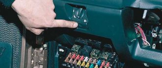
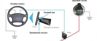
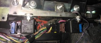
In order to carry out quick checks and repairs, the ignition system relay is installed under the front dashboard of the car, behind the hood release handle. It is located just below the central dashboard. The module is closed with a plastic plug, which must be opened slightly to test for functionality.
Starter, ignition, rear fog lamp relay
Next to the indicated relay, there is a similar one for the rear fog lights and the starter.
The main task of the relay when igniting is to reduce the applied load to the contacts. When the engine starts, the relay turns off some electrical circuits in the vehicle system. The system is used not only in injection, but also in carburetor engines.
In the event of a malfunction or malfunction in the ignition system, it is necessary to monitor the operation of the relay. For this purpose, open the box and carefully remove the desired element. It is attached using contacts to special grooves. The first thing to do is look at the oxidation of the contacts, if necessary, clean them with a soft cloth or treat them with a special liquid.
To check functionality, you need to use a regular multimeter. We connect to incoming connections and check the numbers. If there is no short circuit when current is applied, it means the element is not working. Replacement is carried out in a similar manner. It is necessary to use a standard element with the number of amperes indicated on the housing.
Location in the car
There are two types of location of turn signals in the classic VAZ family of cars, depending on the modification:
Let's start disassembling
- Early modification models
To get to the relay, you need to remove the plug by unscrewing the bolt on the dashboard.
We pull the entire panel towards us, move the sensor panel a little to the side so that we can get to the relay.
- The contacts approach the relay from below.
- Disconnect the contacts.
- We remove the old device and install the new one.
- We put the dashboard back, sliding it into the side grooves.
- Screw in the bolt.
We check the turn signals for flickering and characteristic clicks. The frequency of contact closure should be approximately 1 time per second.
The technology is very simple. The main difficulty here is accessibility to the relay. The space under the panel of these models is small, getting there is problematic.
- Later models
- Remove the screws from the steering column switch housing. We remove the casing elements.
- Unscrew the mounting bolt.
- We take out the devices on the electrical wiring inside the cabin.
- We replace the old relay with a new one.
- Screw it back. We put the covers in place.
Important: it is recommended to replace the relay itself or the mounting block as an assembly, given that the wiring often burns out and restoring the contacts is quite problematic.
When replacing any of the above relays, special attention should be paid to contact insulation. Insulation is performed using hollow mass braiding. To tie the wires, use a special strip clamp.
Functions of VAZ-2115 fuses
A fuse in cars is a fuse-link that performs protective functions for current-carrying circuits. Such functions are aimed primarily at blocking either the entire circuit or an individual node from overloads. This is due to the fact that any vehicle is equipped with an on-board network with a whole set of circuits that conduct electric current. Their task is to ensure the uninterrupted functioning of the vehicle’s electrical equipment. Each section of the current-carrying circuit has its own specific fuse with the corresponding marking.
A standard automotive fuse is a small part, in a plastic body of which a filament of low-melting metal is placed, which acts as a conductor. If an overload occurs in a current-carrying circuit, this conductor thread will melt, which will cause a break in this circuit.
Due to this gap, a certain section of the on-board network will be de-energized and fail.
How to check
First of all, see if the indication installed on the dashboard continues to work. If it also does not turn on, then reach into the mounting block - the fuse has probably blown.
When the control is functioning and the protective device is in order, then activate the VAZ emergency lights and see how well the lamps in the headlights glow. Moreover, this must be done both in front and behind. Excessive dullness indicates an incorrect rating or poor ground contact.
When the turn signal does not work, you should look at the relay. Make sure that current is flowing to its terminals.
Proceed like this:
- remove the housing of the electromagnetic device;
- connect one tester probe to its positive contact;
- Place the second probe on ground.
Instead of a measuring device, it is permissible to take a light bulb with wires soldered to it. It is not necessary to activate the ignition at all.
If there is no electricity, then most likely:
- the button that starts the emergency lights is broken;
- there is a break in the circuit;
- the fuse responsible for the turn signal has burned out;
- Somewhere the contact is lost.
When current flows, as evidenced by a glowing lamp or tester readings, it is necessary to close the relay contacts directly. If all other elements of the circuit work, then the turn signal should light up. The absence of a positive result indicates the failure of the mentioned device.
Image of VAZ-2115 fuse diagram
A fuse diagram for a vehicle is usually at hand for every car enthusiast. But how to understand all the icons and markings? This will be discussed in this article.
Functions of VAZ-2115 fuses
A fuse in cars is a fuse-link that performs protective functions for current-carrying circuits. Such functions are aimed primarily at blocking either the entire circuit or an individual node from overloads. This is due to the fact that any vehicle is equipped with an on-board network with a whole set of circuits that conduct electric current. Their task is to ensure the uninterrupted functioning of the vehicle’s electrical equipment. Each section of the current-carrying circuit has its own specific fuse with the corresponding marking.
A standard automotive fuse is a small part, in a plastic body of which a filament of low-melting metal is placed, which acts as a conductor. If an overload occurs in a current-carrying circuit, this conductor thread will melt, which will cause a break in this circuit.
Due to this gap, a certain section of the on-board network will be de-energized and fail.
How to distinguish fuses from each other on a diagram
On the VAZ-2115, car fuses, in addition to special markings, are painted in different colors. This is done for convenience: each specific color corresponds to one of the calculated current values in accordance with GOST conditions:
- gray – 2 A;
- pink – 4 A;
- orange – 5 A;
- brown - 7.5 A;
- red – 10 A;
- blue or blue - 15 A;
- yellow – 20 A;
- white – 25 A;
- green – 30 A.
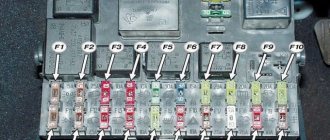
On the VAZ-2115 fuse diagram, 20 elements are marked, each of which corresponds to a marking with the English letter “F” and a digital designation. It is by the alphanumeric marking that you can find the desired fuse, which is responsible for a specific section of the conductive circuit:
- Rear fog lights – F1.
- Turn signal repeaters – F2.
- Car interior lighting – F3.
- Rear window heating – F4.
- Radiator fan, signal – F5.
- Electric windows – F6.
- Cigarette lighter, washer motor – F7.
- Front fog lights – F8-F9.
- Left-hand dimensions, front and rear license plate lighting, instrument panel lighting - F10.
- Right-hand dimensions – F11.
- Low beam headlights – F12-F13.
- Driving lights – F14-F15.
- Instrument panel indicator lamps – F16.
- Reserve safety elements for VAZ-2115 injector – F17-F20.
But in addition to the listed main safety elements, which are located in the mounting block of the engine compartment (on the left side under the windshield), the VAZ-2115 has several additional fuses. Additional safety elements are located in the vehicle interior itself - under the dashboard under the glove compartment on the passenger side. This arrangement of three additional fuses is due to their functional feature - they are responsible for the operation of the main engine systems. Such systems include:
- power supply for the gasoline pump – top location of safety elements;
- cooling fan, canister purge valve, speed sensor, crankshaft position and mass air flow sensor - middle location;
- central relay, ECU - bottom location.
As you can see, all of the above automotive parts perform important functions, so the safety elements for them must be protected from external influences, mechanical damage and negative environmental influences.
When there is a need to use a VAZ-2115 fuse diagram
Motorists use the diagram, which shows the placement of safety elements, to carry out the procedure for replacing those that have failed, that is, burned out. Car fuses blow out for several reasons:
- Short circuit in the current-carrying circuit.
- Overload in the entire on-board network.
- The use of additional electrical appliances that have greater power than the current values in the on-board network.
Short circuits can most often be observed when wires are broken, automotive electrical appliances are in a faulty condition, or moisture gets on their contacts.
As soon as the inactivity of a certain device (for example, a cigarette lighter) is noticed, the first thing to do is check its fuse. And to figure out where a specific safety element is located, you need to know the diagram and all the symbols on it.
Design and principle of operation of an electromagnetic-thermal turn relay
Relays of this type do not have a very complicated design. It is based on an electromagnetic relay of a traditional design - a cylindrical core with a winding of thin copper wire. At the top of the core there are two contact groups, and on the sides there are flexible metal anchors (or, as they are called, anchors). One contact group is designed to close the circuit of the turn signal indicator lamp located on the dashboard. And the second contact group directly closes the circuits of the direction indicator lamps, and it is its design features that ensure the blinking of the turn signals.
The armature of the contact group of the turn signal lamps is pulled away from the contact located on the core using a thin nichrome string, so in the normal position the turn signal circuit is open. The opposite end of the string is fixed on a platform made of insulating material, which serves as the basis for installing the core. The nichrome string is connected through a resistor to the turn signal switch circuit, so current flows through it during operation of the relay.
This entire structure is placed in a cylindrical metal case; the bottom of the case is a platform made of insulating material with a relay. At the bottom of the platform there are contacts with the help of which the breaker relay is connected to the turn signal circuit.
The operation of an electromagnetic-thermal relay is quite simple and boils down to the following. When the turn signal is turned on, a circuit is closed that includes the turn signal lamps, a resistor, a relay winding and a nichrome string. Due to the resistance of the resistor, the voltage supplied to the lamps is low, so their filaments burn at full heat. Nichrome, as is known, has a high resistivity and heats up greatly when current flows - thanks to this heating, the nichrome string increases its length, and the armature pulled by it, under the influence of the attraction of the core, straightens and at some point closes the contact group. As a result, current begins to flow bypassing the resistor and the nichrome string, and the turn signal lamps light up in full force.
However, stopping the heating of the string leads to its cooling and shortening, and the armature is again pulled away from the core, opening the contacts - the turn signal lamps go out, and the cycle repeats again. The heating and cooling of the nichrome string occurs quickly, so the lamps blink at a frequency ranging from 60 to 120 times per minute.
The current position of the contact group of the direction indicator lamps (let's call it the first) is associated with the work of the contact group of the signal lamp (let's call it the second). When the contacts of the first group are open, current flows through the winding, but it is not enough to attract the armature of the second group, so the signal lamp does not light up. When the string is pulled and the first contact group is closed, the current flowing through the winding increases sharply, and it is already sufficient to attract the armature of the second contact group. As a result, simultaneously with the blinking of the direction indicators, the warning light on the dashboard also blinks.
Characteristic clicks during operation of the direction indicators occur due to the impact of the anchors on the contacts when they are closed and opened. Clicking is a characteristic feature of electromagnetic relays, and it comes in very handy in breakers.
The electromagnetic-thermal relay has a simple design, and this is its main advantage. But this type of relay has many more disadvantages: over time, the string is stretched, as a result of which the relay stops functioning normally, during operation the relay heats up, which changes its characteristics, and if one of the turn signal lamps burns out, the blinking frequency of the second lamp decreases significantly, and In some cases, the lamp stops lighting up altogether.
Today, electromagnetic-thermal relay-interrupters have been replaced by more modern and advanced electronic relays.
Some useful tips
To ensure that the fuses in your VAZ-2115 last longer, and the failure of any of them does not take you by surprise, use the following tips:
- At least once a quarter, check the condition of the mounting block, its board and the protection elements installed in it. Do not allow moisture or dirt to get inside. If necessary, take care of its additional protection.
- When undergoing maintenance, ask an auto electrician to check the performance of the vehicle’s on-board network. If they deviate from the norm, take care of repairing the machine.
- Do not overload the vehicle's on-board network. Do not use electrical appliances that consume high current.
- Under no circumstances use homemade bugs instead of fuses. This can cause not only a short circuit, but also a fire in the machine.
- Carry a spare set of fuses with you. It costs 150-200 rubles, takes up virtually no space, and can help out at the right time.
Never do this in church! If you are not sure whether you are behaving correctly in church or not, then you are probably not acting as you should. Here's a list of terrible ones.
What does your nose shape say about your personality? Many experts believe that you can tell a lot about a person's personality by looking at their nose.
Therefore, when you first meet, pay attention to the stranger’s nose
11 Weird Signs That You're Good in Bed Do you also want to believe that you please your romantic partner in bed? At least you don't want to blush and apologize.
15 Cancer Symptoms Women Most Often Ignore Many signs of cancer are similar to symptoms of other diseases or conditions, which is why they are often ignored.
Pay attention to your body. If you notice
7 Body Parts You Shouldn't Touch with Your Hands Think of your body as a temple: you can use it, but there are some sacred places that you shouldn't touch with your hands. Research showing.
10 charming celebrity children who look completely different today Time flies, and one day little celebrities become adults who are no longer recognizable. Pretty boys and girls turn into...
Types of problems and troubleshooting methods
The turn signal works correctly if the following indicators are met:
- the presence of the ignition on ensures the operating mode;
- moving the steering column switch up and down must be accompanied by turning on the turn signal on the corresponding side;
- The turn signal should flash at a rate of 60 cycles per minute.
Any other turn signal behavior indicates a problem. The most common causes of malfunctions include:
Non-blinking turn signal. The problem requires familiarity with the basic principle of relay operation: the current passing through the lamps leads to heating of the measuring resistor - an element that determines whether a particular lamp needs to be turned on. Consequently, the lamp resistance, different from the nominal one, changes the time the turn signal is turned on: it begins to blink. In this situation, it is recommended to lightly tap the relay (this helps if there is a weak connection or moisture). If you have replaced the relay, but the turn signal does not blink, but is constantly on, then there is poor contact with the fuse block. Replacing a fuse that was found to have a resistance value that does not correspond to the nominal value can also help.
Stopping the operation of one turn signal is incompatible with a relay malfunction (problems of this type cause the operation of both turn signals to malfunction). One of the turn signals may fail due to a burnt-out light bulb (the simplest option) or a faulty wiring or socket. The new tab must not only fit into the turn signal socket, but also correspond to the power indicated on the lamp
If after replacing the light bulb the turn signal still does not start working, you need to pay attention to the socket. If there are traces of oxidation on it, then you should start removing them
Sandpaper or a needle file works well for this. And if the light bulb is in too tight contact with the contacts, then you need to bend them with thin-nose pliers. This must be done as carefully as possible, preventing the contacts from closing, which can lead to another problem - the turn signals working in a checkerboard pattern. The normal state of the cartridge means that the cause of the malfunction lies in the wiring. First you need to make sure that the wire is securely connected to the socket. In this case, it is unacceptable for the wires to be closed to each other or to have a ground short to the metal body of the car. In this case, it is necessary to replace the wires or at least insulate them. If at the same time the hazard lights do not work, then the relay definitely needs to be changed - it is faulty.
Also, the reason for the turn signal not working may be the switch itself. To check it, you need to get to the steering column switch and unmount it. By the way, if a problem occurs in the form of a hazard warning light that does not turn on when there are normally working turn signals, you just need to replace the button responsible for turning on the emergency lights.
A dim turn signal light is a signal to check the suitability of the model and power. If everything is in order, then cleaning the contacts of the light bulbs can correct the situation.
A turn signal relay making a clicking sound is also not normal. The malfunction is hidden in the mounting block, or more precisely, in the relay contacts. Clicking sounds may occur if the contact is oxidized or is too tight. This can also be caused by a defective relay. The problem can be fixed by cleaning the contacts or installing a new relay.
A turn signal that does not work on one side, either front or rear, or in the repeater, indicates that the steering column switch is broken, there is no contact with it, or that the same relay has failed.
The turn signal circuitry is protected by an 8-amp fuse located in the mounting block. If it breaks down, turns will stop working on both the left and right sides of the car.
The light signaling system ensures traffic safety, so the driver should always have at least light bulbs of the required power with him.
Location and electrical diagram
The fuse is turned on simultaneously with the device for which it is responsible. As mentioned above, if the optimal voltage parameters in the circuit are exceeded, the electrical circuit breaks. By the way, in total, power supply elements in vehicles operate for one hundred hours.
VAZ 2114 car
VAZ 2114 vehicles with an injection engine use a single-wire wiring system, which is typical for most cars that exist today. Each, without exception, energy consumer connected to the power supply has its own fuse, which, as a result of an increase in voltage or a short circuit, immediately opens the entire circuit. This is done to prevent overheating of the wiring, and therefore a potential fire.
However, not all devices and instruments of the vehicle are connected to the power supply. Some components of domestic cars require high voltage, which means they cannot be protected by fusible power supply components. For example, these include the circuit of the ignition coil, engine start, and battery. As a rule, the wiring of such components has a much larger cross-section and is equipped with a reliable layer of insulation.
Location of the fusible device block of the VAZ 2114 car
Therefore, take into account the fact that before disassembling the headlights, radio, ventilation system or anything else, you need to make sure that the power supply element itself responsible for this device has not failed. We invite you to familiarize yourself with the diagram and location of the power supply elements and relays in the VAZ 2114 car. The power supply itself is located in the engine compartment, on the left side in the direction of travel of the car. Opening the hood, under the wipers you will see a power supply unit, which is usually painted black. In order to remove the cover, you need to disconnect the two latches on the sides of the power supply.
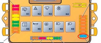
Removing the cover of the box, you will see a device on which nine relays and twenty fuses are located. On the inside of the protective cover there is a diagram identifying the purpose of each power supply device, including the relay. Below we will look at the electrical circuit and the purpose of each individual power supply component.
Electrical diagram of device components
| Number | Purpose |
| K1 | Ensures the functionality of the headlight washer wipers. |
| K2 | Responsible for the operation of direction lamps, as well as light signaling. |
| K3 | Windshield cleaner. |
| K4 | Ensures the functioning of the light bulb, which is responsible for the operation of other lamps. |
| K5 | This relay is responsible for the operation of the power windows. |
| K6 | The purpose of this relay is to ensure the operation of the steering horn. |
| K7 | Rear window heating device. |
| K8 and K9 | These relays are responsible for the operation of high and low beam lamps. |
We will also consider the purpose of power supply elements responsible for lighting, operation of the stove, cigarette lighter, fuel pump, etc.
Table of assignment of devices of the mounting block of the VAZ 2114 car
Retreat
And comrades, let’s make one more digression from the topic; it is important mainly for novice drivers who have recently gotten behind the wheel and are not yet familiar with the structure of the car.
I want to say that on the instrument panel there is a red oil pressure light (oil can). If it lights up, stop the car, turn it off, and call your friends so they can drag you to a car service center on a rope. Driving with this light on is strictly prohibited. If you decide to drive home, and then figure out what kind of light it is and why it is on. Then be prepared to replace the engine. This is the engine oil pressure light. If it lights up, this indicates that the engine has run out of oil, or there is an internal engine malfunction, or the sensor has failed. In any case, you should immediately stop driving and turn off the engine. And perhaps the repair will not cost you that much. I hope my warning will keep someone’s engine and pocket intact.
Fuse Location
For ease of maintenance, most fuses are installed in a special mounting block, and here the VAZ-2115 injector is no exception. You just need to know that this model has two of them installed.
The first one in the VAZ-2115 (equipped with an 8-valve engine) is located directly in the cabin, under the dashboard, at the steering wheel. The other one is installed near the engine, that is, under the hood, next to the left glass.
Any of the fuses located in the mounting block has its own specific designation, based on this, it is not difficult to find out which circuit it is responsible for.
So the fuse is marked:
- K1 – protects the relay that turns on the headlight cleaning from overvoltage;
- K2 – for emergency signaling and switching of turn signals;
- K3 – power supply for the “janitors”;
- K4 – lighting;
- K5 – window regulators;
- K6 – horn;
- K7 – rear window heating element;
- K8 – high beam headlights;
- K9 – close;
Below are fuses with fuse links, which are designated F and have a serial number. Each of them is designed for a specific current.
The unit installed in the cabin is slightly different from the one described above. It contains, in particular:
- relays (3 pieces);
- ECU;
- fuses (3).
Each of the latter is designed to protect a specific circuit from overvoltage and short circuit.
Down up:
- on-board computer power supply (7.5 A);
- radiator cooling fan, and in addition an adsorber valve, mass air flow sensors, DC and DC sensors (7.5A);
- fuel pump (15 A).
As noted earlier, this block also contains three relays. Down up:
- Basics.
- Radiator fan control.
- Responsible for the operation of the fuel pump.
Relay under the hood
The main one is the fuse box near the engine. The vast majority of fusible protective elements and almost all relays are located here. During the existence of the model, its modifications changed several times. The most common modern block was presented in 2008. In this release, the arrangement of individual elements has changed slightly and new ones have been added.
You can find the block in the engine compartment above all the devices in the engine compartment. It is protected by a cover that can be easily opened by pressing two latches.
Fuses and relays VAZ 2114, 2115, 2113
Today, every car, regardless of type, is equipped with special protection for all electrical systems. This protection is called a fuse. They are installed so that in the event of a short circuit or malfunction, the system can turn off via a fuse, thereby protecting itself from breakdown. Fuses are used for every electrical circuit, from a small light bulb to an engine's ignition system. More important engine systems are equipped with special relays, they protect various pumps, electric motors and other powerful sources of electricity consumption.
The fuse is a small structure consisting of a plastic casing with a fusible element inside. If a short circuit occurs, the thin contact melts under the influence of current, which interrupts the electric current. The simplest electrical fuse is a thin copper wire inserted into a circuit. If the upper limit of the supplied current increases, the contact begins to melt and interrupts the flow of electricity. Here there is a description of all fuses and relays for VAZ 2113, 2114, 2115 models of injection and carburetor types, old and new models.
Purpose of the turn relay
The Traffic Rules in force in Russia clearly state that when making maneuvers, it is necessary to turn on the direction indicators, and in their absence, indicate the direction of movement with your hand. However, now most cars and motorcycles are equipped with turn signals, so you rarely need to use your hands to indicate the direction of travel.
When turned on, the direction indicators flash, that is, they light up and go out at certain intervals, so they attract the attention of other road users, and it is quite difficult not to notice the turn signal being turned on. The blinking of direction indicators also serves another role - it does not allow drivers to confuse their activation with the activation of brake lights or the activation of side lights.
Periodic turning on and off (that is, the same blinking) of the direction indicator lamps is realized using a simple device that is part of the vehicle's electrical system - a turn relay, which is often simply called a breaker or breaker relay.
The breaker relay included in the turn signal circuit performs three functions at once:
- Supplying electric current to the direction indicator lamps (that is, turning on the “turn signals”);
- Ensuring intermittent operation of the direction indicator lamps (their blinking);
- Creation of characteristic clicks, signaling to the driver of the car that the direction indicators are working.
In cars of the Volzhsky Automobile Plant of various generations and models, several types of turn relays are used, which have different operating principles and characteristics.
Turn relay VAZ-2108,2110,GAZ-31105,GAZelle Next AVAR
Turn relay VAZ-2104,05,07,GAZ-3110;3302 AVAR
Turn relay VAZ-2108-10, M-2141 AUTO RELAY
Turn relay VAZ-2101-03 AVTOPRIBOR
Turn relay VAZ-2104-07 AENK-K
Turn relay VAZ-2104,05,06,07 4-pin. AUTOPRIBOR
Turn relay VAZ-2108,2110 EM
Explanation of the additional fuse and relay block
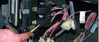
To turn on the main systems of any car, the manufacturer has designed the installation of auxiliary fuses. As a rule, they are located in the center console area. Each auxiliary module consists of several important relays and fuses.
In this particular case, the box is located to the left of the glove compartment, behind the side trim of the center console. To quickly access the box, you need to remove part of the plastic protection. The protection is attached to Phillips bolts, so you need to prepare the appropriate screwdriver.
Table 3. Explanation of the additional fuse and relay block
There are also options for other decryptions.
Explanation of the additional fuse and relay block
Relay:
Fuse:
f2 - main relay;
f3 - ECU (electronic control unit).
Relays that control the supply of current are present in the design of many vehicles. They are designed to perform a very important function - they turn on and off important electrical devices and mechanical systems of the vehicle. In simple terms, this is a device for supplying current to a required element.
What problems might you encounter when replacing?
Fuses and relays Mercedes w124
The main problem that arises when replacing a fuel pump is the lack of the expected result: there is no fuel supply, or it is supplied intermittently.
Therefore, before starting all work, you need to make sure that the problem is really in the pump itself. After all, a weak fuel supply can be caused by a clogged fine filter, problems with the fuel lines - sometimes they can simply bend somewhere in an unexpected place, or dirty injectors on the fuel rail.
Even an air filter that is not replaced on time or a coked throttle valve can cause effects that look similar to insufficient fuel supply. But the most common problem is a poor contact in the electrical connector of the fuel module or a simply blown fuse.
Good luck to you and your car friend! Be always healthy!
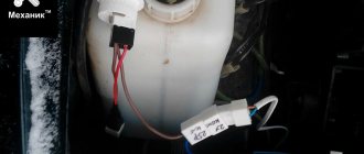
Fuel pump fuse VAZ 2115
The pump relay is the lowest. Its fuse is also at the very bottom. When you turn the key, the relay turns on for 5 seconds in order to pump up pressure in the system and turns off. After the engine starts, control of the pump passes to the computer.
The mass of the pump (and fuel level sensor) is attached to the stud securing the handbrake to the body under the carpet. To get to it you need to remove the vestibule between the passenger and driver seats. There are 3 wires going to the fuel pump. first +, second minus, third fuel level sensor.
Where is
If we describe them from top to bottom, we get the following:
1. The fuse that controls the fuel pump. Its current strength is 15 amperes.
A fuse is a small element whose task in the design of electrical circuits is to melt in the event of an overload. The device melts and the current-carrying circuit opens.
Using the example of a solution from the popular VAZ Priora model, we can superficially examine the design and operating principle of the fuse. The device is small, the outer casing is made of plexiglass.
There is a conductive element inside. Such an element is based on several plates, which are made of different materials. Between these plates there is a special low-melting material. Electricity passes through this material, which allows the fuse to be an integral part of the electrical power circuit of the fuel pump. Fuses have a special marking in the form of the letter F. This designation indicates that the fuse element belongs to a circuit whose power is not large. To calculate the current that certain devices are designed for, you need to divide the power by 220. The result will be a figure in amperes.
If the fuse is blown, then such a malfunction is often caused by the following reasons:
— short circuit in the electrical circuit;
— failure of the fuel pump relay;
- low quality of the fuse itself;
In other words, more often the fuel pump fuse blows due to faults in the electrical circuits or as a result of failure of the components of the pump power circuit. Note that situations also arise when the fuel pump fuse burns on its own, but this phenomenon occurs much less frequently with high-quality elements.
How to identify a malfunction
The fuel pump relay turns on the fuel pump and delivers fuel to the injectors. The safety relay is activated when the engine is not running and the ignition is on (the control unit does not receive speed signals). This relay is switched off in the control unit via a safety switch and interrupts the power supply to the pump. For example, in the event of an accident, gasoline cannot flow into the engine. Checking the fuel pump is a job most likely reserved for service centers. In this regard, to find errors, we will limit ourselves to the following points:
— disconnect the fuel supply line at the distributor, while preparing a rag for spilled gasoline;
— even when the engine is turned off, a certain amount of gasoline may come out, since the system is under pressure;
— turn on the ignition for a short time without turning on the starter;
— if the pump does not start working, check the fuse or safety relay again;
— if fuel does not flow, check the pump relay;
— if the relays are working properly, the fuel pump should start working;
- otherwise, remove the cover under the rear seat and carefully tap the pump housing with a small hammer - sometimes it helps;
— check the correct connection of the wires to the fuel pump;
- if the pump does not work, check the voltage using a diode bridge (a conventional test lamp can damage the control unit). Don't forget to turn on the ignition first;
- if the voltage is normal, it means the pump is damaged or there is an open circuit. The pump should be replaced with a new one.
Other causes of fuel pump malfunctions
Quite often, unprofessional installation of additional electrical equipment or security anti-theft systems leads to the fact that the power to the fuel pump is lost due to mixed up contacts or other connection errors.
Finally, let’s add that the gas pump in the gas tank is immersed in gasoline, in which it is actively cooled. The habit of driving with an empty tank can quickly damage the electric motor of the fuel pump, as it burns out.
What functions does the fuel pump relay perform, signs of breakdown. Where is the fuel pump relay installed, how to properly check the fuel pump relay.
Why does the starter turn normally, but the engine does not catch and does not start? Main causes of malfunction, checking fuel supply and ignition systems. Adviсe.
Diagnose faults that may indicate problems with the fuel pump. Self-check of the device, measuring the pressure in the fuel rail.
The causes of whistling and increased noise during operation of the fuel pump are overheating of the pump. How to diagnose and fix the problem yourself. Tips and tricks.
How to change a fuel pump. Location of the fuel pump, releasing pressure in the system, unscrewing the fuel lines, removing the pump, reassembling.
What to do if the car accelerates worse, does not pick up speed, or has failures during acceleration. Why the engine does not pull, how to find the reason for the decrease in power.
- Signs of breakdown
- Popular breakdowns
- Pump replacement
It's no secret that you can't get far in a car without gasoline. Therefore, for the engine to operate, it is simply necessary that the entire fuel system functions in optimal mode.
In many ways, the fuel pump is responsible for supplying fuel to the engine, which the VAZ 2114 model is not without, of course. To solve a problem with a faulty fuel pump, you need to make sure it is at fault.
Decoding the plugs of the mounting block of fuses VAZ 2114, 2113, 2115 model 2114-3722.010
| Table for decoding the terminals of the VAZ 2114, 2113, 2115 fuse mounting block | |||
| Plug connector designation | Terminal number | Wire color | Device name |
| Ш1 | 1 | B | window lifters |
| 2 | G | ignition switch (cl. 15/2) | |
| 3 | GP | ignition switch (terminal 15) | |
| 4 | ZhG | heater motor switch | |
| 5 | R | ignition switch (cl. 30/1) | |
| 6 | KR | ignition switch (terminal 30) | |
| 7 | door lock | ||
| 8 | P | ignition switch (terminal 50) | |
| Ш2 | 1 | BG | rear window wiper switch |
| 2 | G | Turn signal switch (right) | |
| 3 | RP | brake light switch | |
| 4 | B | lamp continuity indicator | |
| 5 | IF | hazard warning switch | |
| 6 | GB | left front door | |
| 7 | ABOUT | rear fog light switch | |
| 8 | 34 | high beam warning lamp | |
| 9 | -/td> | ||
| 10 | 04 | rear fog light switch | |
| 11 | midrange | fuel reserve warning lamp | |
| 12 | pch | fuel level warning lamp | |
| 13 | Warhead | interior lamp | |
| 14 | kg | hand brake warning lamp | |
| 15 | hh | Turn signal switch (left) | |
| 16 | electric motor for headlight cleaner | ||
| 17 | — | ||
| Ш3 | 1 | and | speed sensor |
| 2 | emergency | hazard warning switch | |
| 3 | gp | direction indicator switch | |
| 4 | Sat | oil level warning lamp | |
| 5 | h | weight | |
| 6 | RB | washer fluid level warning lamp | |
| 7 | ro | brake lining wear warning lamp | |
| 8 | 3v | headlight switch | |
| 9 | zhz | windshield wiper switch | |
| 10 | pg | portable lamp connection socket | |
| 11 | O | ignition switch (terminal 15) | |
| 12 | RF | rear window washer switch | |
| 13 | |||
| 14 | and | fog light warning lamp | |
| 15 | |||
| 16 | sg | oil pressure indicator | |
| 17 | |||
| 18 | R | wiper switch | |
| 19 | with | wiper switch | |
| 20 | With | wiper switch | |
| 21 | about | rear fog light switch | |
| Ш4 | 1 | salary | On and indicator lamp for heated rear window |
| 2 | GB | headlight switch (high beam) | |
| 3 | O | wiper | |
| 4 | warhead | outdoor lighting switch | |
| 5 | To | Instrument lighting rheostat | |
| 6 | R | battery | |
| 7 | bw | windshield wiper and washer switch | |
| 8 | O | block Ш4 of the mounting block terminal 3 | |
| 9 | sch | horn switch | |
| 10 | bp | brake light switch | |
| 11 | R | battery | |
| 12 | joint venture | headlight switch (low beam) | |
| 13 | warning light | ||
| 14 | — | ||
| 15 | — | ||
| 16 | rg | brake fluid level warning lamp | |
| 17 | zb | coolant temperature gauge | |
| 18 | kb | battery charge indicator lamp | |
| 19 | zhch | fog light switch | |
| 20 | rz | coolant level warning lamp | |
| 21 | and | tachometer | |
| Ш5 | 1 | 3 | high beam (right) |
| 2 | zch | high beam (left) | |
| 3 | sch | low beam (left) | |
| 4 | P | starter (cl. 50) | |
| 5 | pb | electric radiator cooling fan | |
| 6 | With | low beam (right) | |
| Ш6 | 1 | — | |
| 2 | 3 | reverse light switch | |
| 3 | hh | Turn signal (left front) | |
| 4 | |||
| 5 | — | ||
| 6 | — | ||
| 7 | — | ||
| 8 | zhch | side light (right front) | |
| 9 | warhead | electric fan thermostat | |
| 10 | zhch | side light (left front) | |
| 11 | G | Turn signal (right front) | |
| 12 | O | reverse light switch | |
| 13 | rg | brake fluid level sensor | |
| Ш7 | 1 | — | |
| 2 | zhg | electric motor for headlight cleaner | |
| 3 | b | electric motor for headlight cleaner | |
| 4 | — | ||
| 5 | Sat | oil level sensor | |
| 6 | sch | sound signals | |
| 7 | With | speed sensor | |
| 8 | zb | coolant temperature sensor | |
| 9 | kb | generator (cl. 61) | |
| 10 | R | windshield washer pump | |
| 11 | warhead | engine compartment lamp switch | |
| 12 | RB | washer fluid level sensor | |
| 13 | RF | brake linings | |
| 14 | |||
| 15 | kp | tachometer | |
| 16 | rz | coolant level sensor | |
| 17 | reinforced concrete | fog light relay | |
| Ш8 | 1 | zhl | fog light relay |
| 2 | zhch | fog lamp (left) | |
| 3 | and | fog lamp (right) | |
| 4 | gp | ignition coil | |
| 5 | R | generator (cl. 30) | |
| 6 | R | generator (cl. 30) | |
| 7 | |||
| 8 | RF | fog light relay | |
| Ш9 | 1 | RF | electric motor rear window wiper |
| 2 | G | Turn signal (right rear) | |
| 3 | bg | electric motor rear window wiper | |
| 4 | very good | rear fog lights | |
| 5 | sch | back door | |
| 6 | pch | front right door | |
| 7 | warhead | interior lamp | |
| 8 | kg | handbrake sensor | |
| 9 | warhead | open door alarm buttons | |
| 10 | rear window heating elements | ||
| 11 | With | license plate light | |
| 12 | GB | front left door | |
| 13 | b | interior lamp | |
| 14 | P | brake lights | |
| 15 | and | side light (right rear) | |
| 16 | h | reversing light | |
| 17 | zhch | side light (left rear) | |
| 18 | zhch | rear window cleaner | |
| 19 | O | rear window heating elements | |
| Ш11 | 1 | and | pump |
| 2 | RF | rear window washer valve | |
| 3 | |||
| 4 | and- | pump | |
| 5 | warhead | engine compartment lamp | |
| 6 | |||
| 7 | |||
| 8 | CC | engine compartment lamp | |
| 9 | b | electric windshield wiper motor | |
| 10 | O | windshield wiper motor | |
| 11 | |||
| 12 | with | emergency oil pressure sensor | |
| 13 | |||
| 14 | R | windshield washer valve | |
| 15 | with | electric wiper motor | |
| 16 | With | electric windshield wiper motor | |
| 17 | reinforced concrete | electric windshield wiper motor | |
| 18 | |||
| 19 |
Wire colors:
- B - white;
- G - blue;
- F - yellow,
- 3 - green,
- K - brown;
- O - orange;
- P - red;
- P - pink;
- C - gray,
- H - black.
We are looking for a breakdown with our own hands
Primary diagnostics can be carried out with a test light, but a tester is required to check the condition of the circuit. If you know, then in the resistance measurement mode you can independently “ring” the wiring for a break.
If you clearly hear the relay clicking when you turn on the right/left turn signal, check the resistance of the section of the circuit with the steering column switch. If only the left or right side does not work, the reason is definitely in the switch or in the wiring of the circuit from it to the light bulbs.
If the turn signal relay does not click at all, check the condition of the contacts, the positive wire and ground. If, after turning on the ignition, “+” does not come to the relay, the problem is most likely in the section of the circuit from the mounting block to the relay.
Understeering's shifter
The cause of the malfunction can be either mechanical damage to plastic or contact elements, or the formation of carbon deposits. During operation of the turn signals, the contacts may burn out, which increases the resistance and reduces the current in the circuit. It is typical that in the case of oxides and carbon deposits, the indicator relay may click, but the lamps will not light up.
To repair the steering column switch, you will need to remove it from the steering column and disassemble it. There are many contact pads inside the case, so for trouble-free assembly, remember the location of all moving elements.
Where is it located and how to check the turn signal relay
The turn signal relay is located in the fuse box in the passenger compartment or under the hood. You can find out the exact location from the repair and operation manual of your car. Often on the inside of the mounting block the purpose of the relays and fuses is graphically depicted.
Soldering of elements from the circuit, microcracks in solder joints, failure of the main microcircuit are the most common causes of turn signal failure.
Emergency crew
The hazard warning button imitates the steering column turn switch, but closes both contacts at once (on the right and left sides). The video shows the design and operating principle of a simple system, analogues of which are used not only on VAZ cars.
Either one turn signal (“turn signal”) or two may not work, or all at once, etc., in different combinations.
Causes of turn signal failure
1. One turn signal (front or rear) does not work.
Burnt out light bulb
When a bulb burns out in one or more direction indicators on VAZ 2108, 2109, 21099 vehicles, the remaining ones begin to blink at double frequency. We visually determine where the light bulb has burned out, turning on the direction indicators one by one. We replace the light bulb with a working one.
Light bulb socket oxidized
We turn the light bulb in the socket several times to restore contact.
Wire connections are oxidized or loose
We check the cartridges and blocks of the front turn signals (in the front headlights and on the wings) and the connecting blocks of the rear lights of the car.
The “mass” is missing
All lights and lamps of VAZ 2108, 2109, 21099 cars have a negative wire, so you should check its contact with ground.
Burnt out track in the rear light circuit boards
2. Two rear repeaters or two front repeaters do not work.
The first four reasons
the light bulbs burned out, their sockets oxidized, the contacts in the connecting blocks of the direction indicators oxidized (on the headlight unit and the turn signals on the wings), the ground was lost.
Break in the wires going from the mounting block to the rear lights
— In some cases, at the same time, all direction indicators can be lit with a constant light without blinking. In this case, it is necessary to replace the turn signal breaker relay in the mounting block.
The following queries from newbies very often pop up on the Internet: “why don’t the turn signals work?” – we have an answer to this question. Today we will look at the main faults due to which the turn signals on your car do not work.
Often, repairing turn signals is very simple; the main thing is to find the true cause of the malfunction. First of all, I recommend that you watch a video where they tell you how to determine the malfunction.
Video. Turn signals don't work
Let us recall that in the previous article we looked at it with our own hands. This operation can be performed in a garage; do not forget to prepare a large number of containers for antifreeze or antifreeze.
Basic turn signal malfunctions
Turn signals don't blink
When the turn signals on your car stop flashing, most likely the reason lies in the turn signal relay itself. The cause of the malfunction may be simple water that has flooded it or the contact has been interrupted somewhere. We recommend replacing it.
Pinout BN VAZ 2108, 2109, 21099
Where is the fuel pump fuse for the VAZ 2115 injector where is it located?
The fuel pump activation relay (2) is shown by an arrow.
1 — nozzles; 2 — spark plugs; 3 — ignition module; 4 — diagnostic block; 5 - controller; 6 — block connected to the instrument panel harness; 7 - main relay; 8 - main relay fuse; 9 — electric fan relay; 10 — controller power supply fuse; 11- electric fuel pump relay; 12 — fuel pump power circuit fuse; 13 — mass air flow sensor; 14 — throttle position sensor; 15 — coolant temperature sensor; 16 — idle speed regulator; 17 — knock sensor; 18 — crankshaft position sensor; 19- oxygen sensor; 20- APS control unit; 21 — APS status indicator; 22 — speed sensor; 23 — electric fuel pump with fuel level sensor; 24 — solenoid valve for purge of the adsorber; 25 — block connected to the ignition system harness; 26 — instrument cluster; 27 — ignition relay; 28 — ignition switch; 29 — mounting block; 30 — electric fan of the cooling system;
A - to terminal “B+” of the generator; B - block connected to block K of the ignition system harness; C - block connected to block L of the ignition system harness; D - wire connected to the interior lamp switch; E - wire connected to the white and black wires disconnected from the interior lamp switch; F - to the “+” terminal of the battery; G1, G2 - grounding points; K - block connected to block B of the front harness; L — block connected to block C of the front harness.
On “nines” with a mechanical fuel pump, the most common malfunction is wear of the fuel pump diaphragm, as a result of which gasoline will leak through the drainage hole in the housing when it operates. The second reason for the failure of such a fuel pump is wear of the pusher, which transmits force from the camshaft cam to the fuel pump drive lever.
PRINCIPLE OF OPERATION OF THE MAIN ELEMENTS OF A FUEL UNIT
Fuses and relays for Lanos
Fuel system VAZ 2114
CONTAINER FOR STORING COMBUSTIBLE MATERIALS
It is made of steel, consists of two firmly welded parts, the neck through which the fuel enters is connected to the tank with a rubber pipe and secured with clamps.
GASOLINE PUMP
This tool with an electric mechanism is located in a tank with a fuel mixture level indicator. Its actions are coordinated by the engine control box, through a special pump relay, which supplies fuel through the line to the injectors. At idle or when the engine is completely turned off, the pressure is maintained due to the action of a one-way lock, which is located near the unit itself.
The VAZ 2114 power system has a fuel pressure regulator and injectors. The voltage is supplied to them from the battery through the main relay. Thus, the amount of driving fluid is indicated by the duration of the pulses, which are generated by the engine control unit and transmitted to the injectors.
RAMP
Located on the intake manifold, it includes a fuel control element and a pressure valve with a spring-loaded diaphragm. It, in turn, divides the regulator body into 2 parts: the fuel part regulates the pressure of the combustible mixture, the air part, due to the rarefaction of the air, raises the membrane and produces constant fuel pressure readings in the rail.
When the engine starts, the vacuum behind the damper decreases, the diaphragm closes the power system valve, so the pressure increases. When the vacuum is maximum, then the fuel pressure decreases. The regulator is not dismountable, so if it fails, it is replaced with another one.
FUEL MIXTURE CONTROL SENSOR
The pump module has a float, which is located in the tank cavity. When the position of the float changes, the resistance of the unit changes proportionally. According to a certain signal, the fuel quantity indicator on the dashboard displays the presence of fuel in the system.
Why does the sensor often fail?
Due to:
- fragility of the case;
- frequent temperature changes;
- condensation formation in the tank;
- when using a low-quality combustible mixture;
- oxidation of contacts when sealing is broken.
That is why it is so important to carry out preventive maintenance on time, clean the unit, change contacts in order to prevent its destruction. Changing a device is not that easy. Many markings are original and unique, which means that the services of professionals will be required, which are also not cheap
HOSES AND PIPES
Such irreplaceable products guarantee uninterrupted circulation of flammable liquid from the container to the main line and nozzles, and if there is excess, they transfer the residual liquid back to the tank. The pipelines are located on the bottom of the vehicle, they need to be carefully checked, cleaned, inspected for integrity, various deformations identified and promptly eliminated in order to avoid fuel leakage, as well as poor transmission to the injectors.
Another function of the pipelines is the transfer of fuel vapor from the tank to the activated carbon section, where waste is collected when the engine is turned off. After it is started, the electromagnetic device is triggered and the vapors escape into the engine, where they are destroyed.
HIGHWAY
The design of the VAZ 2114 fuel system includes a main line that guarantees the supply of fuel to all injectors. Today, the fuel pressure regulator is placed in the tank and is not located on the line; there is also a service valve, which performs the function of eliminating air after a technical inspection of the vehicle.
The fuel injection system of the VAZ 2114 includes an uninterrupted mode for collecting fuel vapors, and the gravitational unit located in the device helps prevent fuel from leaking when the vehicle is in an emergency position.
When the engine's air consumption is high, the system is purged more intensively. The filter element is made of durable paper material, after which the air moves through the mass air flow sensor and moves into the intake hose, which leads to the throttle assembly.
Thus, the operation of the fuel fluid supply mode of an engine with a fuel injection system on a VAZ 2114 car occurs.
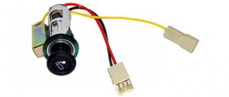
The cigarette lighter does not work on the VAZ 2115
In modern car operating conditions, drivers in most cases use the VAZ-2115 cigarette lighter socket not for its intended purpose, but as an outlet for connecting additional devices to it, as a power source, which are now sold in abundance in Russian automotive spare parts stores . But those drivers who do not think about the consequences of such actions often pay for it with repairs related to replacing the cigarette lighter socket or even repairing the mounting block.
The main reason for the failure of the cigarette lighter is that the plugs of additional devices, especially imported ones, through which they receive power, although slightly, still differ in diameter and the length of the protrusion of the central contact, to which the positive must be supplied from the current source.
If the central contact of the plug is slightly short, then when it is installed in the cigarette lighter socket, the antennae attached to the positive contact of the cigarette lighter socket move apart.
This can lead to these antennae touching the body of the cigarette lighter socket, to which the wire going to the ground of the car is connected.
As a result, a short circuit occurs and the fuse protecting this electrical circuit blows.
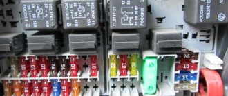
To replace a blown fuse, you will have to open the cover of the mounting block, which has symbols that help the driver quickly find the fuse he needs.
But the problem is that there is no cigarette lighter symbol on it and the driver will have to look for a diagram of the location of the fuses in the mounting block, from which it will become clear that this electrical circuit is protected by fuse F7 (30A).
If, when checking this fuse, it turns out that it is safe and sound, then the driver will need to look at another fuse F4 (20A), which will probably be blown. This is what will have to be replaced. But why F4 burned out and not F7, you need to ask automotive electricians.
Design and principle of operation of an electronic turn signal relay
An electronic relay contains two main parts:
- A conventional electromagnetic relay performing switching functions;
- An electronic key that ensures the relay operates at a certain frequency.
That is, in this type of turn switch, the role of the nichrome string is assigned to an electronic key, which at certain moments supplies and removes voltage from the winding of a conventional electromagnetic relay. The electronic key is built on the basis of microcircuits or discrete elements (transistors), which form a master oscillator and control circuits.
The operation of this relay is extremely simple. When voltage is applied to the relay, the master generator starts working, it generates control pulses having one frequency or another. These pulses are supplied to the control circuits, which provide or interrupt the current flowing through the electromagnetic relay winding. As a result, at moments when current flows through the relay winding, the relay armature is attracted, closing two contact groups - at this moment the turn signal lamps and the warning lamp on the dashboard light up. When the current is interrupted, the armature is released and opens the contacts, all the lamps go out. The lamps blink at the same frequency as in the case of an electromagnetic-thermal relay.
How to eliminate other causes of turn signal failure
There are several other malfunctions that lead to incorrect operation of turn signals, namely:
- The turn signal does not turn off automatically when you turn the steering wheel - the switch will need to be replaced;
- the turn signal blinks very quickly - most likely one of the lamps has burned out (you will need to check and, if necessary, replace it with a new one), however, the reason may be oxidation of the tracks inside the mounting block or oxidation of the chip in the rear lights;
- The turn signals burn very dimly - you will need to clear the ground on the turn signals and also check the installed lamps to ensure that their power corresponds to the required indicators;
- the appearance of clicking sounds when the turn signal is turned on - the cause may be a defective relay or in the relay contacts (they may oxidize or simply not fit tightly).
As can be seen from the information above, eliminating any of the causes of failure of the turn signal relay on a VAZ 2114 is not difficult. It is important to do this in a timely manner, then any trip will be safe, both for you and for other road users.
Sources
- https://remontvazov.com/gde-nahoditsya-rele-povorotov-na-vaz-2114
- https://VazNeTaz.ru/predoxraniteli-i-rele-vaz-2114-2115-2113
- https://auto-prof.site/predohraniteli-i-rele-vaz-2114-2115-2113-predohraniteli/
- https://ladaservice.info/vaz-2113-2115/elektrooborudovanie-vaz-2113-2115/rele-povorotov-vaz-2114/
- https://vaz-2114.info/gde-nahoditsya-rele-povorotnikov-na-vaz-2114/
[collapse]