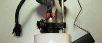
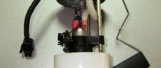
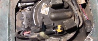
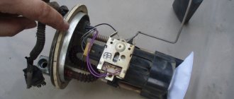
A common failure associated with the fuel system is that the fuel pump fuse blows. In this case, power is not supplied to the pump, and the fuel pump itself stops pumping gasoline into the main line. As a result, the car stalls, the pump does not buzz in the gas tank after turning the ignition key, and the engine does not start.
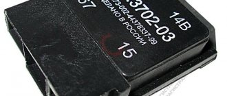
We also recommend reading the article on how to check the fuel pump relay with your own hands. From this article you will learn about where the fuel pump relay is located, as well as the available methods for checking it yourself.
Fuel pump fuse VAZ 2115
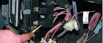
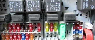
The fuel pump relay is located under the dashboard. On the passenger side, a side panel is opened that covers the beard on which the radio, on-board vehicle, and heater controls are mounted. We see a strip with three relays and fuses.
The pump relay is the lowest.
Its fuse is also at the very bottom. When you turn the key, the relay turns on for 5 seconds in order to pump up pressure in the system and turns off. After the engine starts, control of the pump passes to the computer. The mass of the pump (and fuel level sensor) is attached to the stud securing the handbrake to the body under the carpet. To get to it you need to remove the vestibule between the passenger and driver seats. There are 3 wires coming to the fuel pump: the first is +, the second is minus, the third is the fuel level sensor.
Where is
If we describe them from top to bottom, we get the following:
1. The fuse that controls the fuel pump. Its current strength is 15 amperes.
Lit
A fuse is a small element whose task in the design of electrical circuits is to melt in the event of an overload. The device melts and the current-carrying circuit opens.
Using the example of a solution from the popular VAZ Priora model, we can superficially examine the design and operating principle of the fuse. The device is small, the outer casing is made of plexiglass.
There is a conductive element inside. Such an element is based on several plates, which are made of different materials. Between these plates there is a special low-melting material. Electricity passes through this material, which allows the fuse to be an integral part of the electrical power circuit of the fuel pump. Fuses have a special marking in the form of the letter F. This designation indicates that the fuse element belongs to a circuit whose power is not large. To calculate the current that certain devices are designed for, you need to divide the power by 220. The result will be a figure in amperes.
If the fuse is blown, then such a malfunction is often caused by the following reasons:
— failure of the fuel pump relay;
- low quality of the fuse itself;
In other words, more often the fuel pump fuse blows due to faults in the electrical circuits or as a result of failure of the components of the pump power circuit. Note that situations also arise when the fuel pump fuse burns on its own, but this phenomenon occurs much less frequently with high-quality elements.
How to identify a malfunction
The fuel pump relay turns on the fuel pump and delivers fuel to the injectors. The safety relay is activated when the engine is not running and the ignition is on (the control unit does not receive speed signals). This relay is switched off in the control unit via a safety switch and interrupts the power supply to the pump. For example, in the event of an accident, gasoline cannot flow into the engine. Checking the fuel pump is a job most likely reserved for service centers. In this regard, to find errors, we will limit ourselves to the following points:
— disconnect the fuel supply line at the distributor, while preparing a rag for spilled gasoline;
— even when the engine is turned off, a certain amount of gasoline may come out, since the system is under pressure;
— turn on the ignition for a short time without turning on the starter;
— if the pump does not start working, check the fuse or safety relay again;
— if fuel does not flow, check the pump relay;
Purpose and general structure of the fuel system
A car's fuel system (or fuel supply system) is a system designed to supply fuel (gasoline or diesel) from the fuel tank to the engine (more precisely, to the carburetor or injectors). This system also ensures that fuel is stored and cleaned before being supplied to the engine.
Regardless of type, any fuel system contains several main components:
- Fuel tank;
– Fuel piping system;
- Fuel pump;
– Fuel filter (or filters);
– A device for forming a fuel-air mixture or a device for injecting fuel into the cylinders.
Fuel tank. This is a fuel storage tank. The tank of modern cars is a rather complex system that contains several components: the tank itself, the fuel filler neck, the fuel level sensor, the fuel pump (however, in many systems the pump is installed in the engine compartment) and others. The tank is also connected to a fuel vapor recovery system, which contains a separator, fuel lines, an adsorber and several valves.
Fuel lines. These are tubes that supply fuel from one component to another. Fuel is supplied from the tank by the fuel supply line, and excess fuel is returned from the carburetor, injectors or injection pump (in a diesel engine) through the drain pipelines.
Fuel pump. This is a device that supplies fuel from the tank to the engine. In fuel injection systems, the pump creates high pressure. Diesel engines have two pumps - low and high pressure (a booster pump can also be used in injection engines). Today, electric pumps are most often used, but diesel engines use traditional mechanical plunger injection pumps.
Fuel filters. Usually there are two of them - coarse and fine cleaning. The coarse filter is simply several thin metal mesh installed in the fuel tank. The fine filter is more complex; it is installed in front of the carburetor, ramp or injection pump. Filters ensure fuel purification from various contaminants, dust and foreign solid particles.
The device for forming the fuel-air mixture is a carburetor into which gasoline and air are supplied, where they are mixed and supplied through the throttle valve to the engine intake manifold. In injection and diesel engines, air is supplied by a separate throttle unit, and the formation of a combustible mixture occurs directly in the cylinder.
Fuel injection devices. These are injectors in diesel and injection gasoline engines. However, in diesel engines (as well as in injectors with direct injection), the injectors are installed directly in the cylinder heads, and in injection engines - in the intake manifolds.
Also, the fuel system of modern cars includes a control unit that controls the fuel supply, the formation of a fuel-air mixture and changes in engine operating modes depending on the load and other conditions. The control unit operates based on readings from numerous sensors installed in various engine components and other vehicle systems.
Today, there are two main types of fuel systems - gasoline and diesel engines. Each of them needs to be described in more detail.
Relay and fuse block diagrams for VAZ 2115
The Lada 2115 was first released in 1997 and finished production in 2012. Over such a long period of time, the electronic components of the car have changed significantly. It is not surprising that modifications of the mounting blocks have changed more than once, and with them the fuses of the VAZ 2115.
An old-style car with a carburetor required one installer in the engine compartment. With the advent of a new 8-valve injector, a second unit was needed, installed in the cabin under the dashboard. Some of the new relays were placed under the steering wheel during the 2007 and 2008 upgrades.
The design of the mounting block box has become more modern over time. To make life easier for drivers, a diagram was placed on the lid and tweezers were attached for replacing elements.
Features of fuel filters for the Lada Priora car
VAZ 2170 fuel filters have their own characteristics.
- The coarse filter (FGO) is a fine mesh made of petrol-resistant plastic and capable of trapping solid impurities and dirt larger than 80 microns.
It is made in the form of a flattened bag with a pipe in the middle, attached to the fuel pump using a clamp on the fitting. Fine mesh filters gasoline before it enters the pump - A fine filter (FFO) consists of porous paper assembled into an “accordion” in a cylindrical body made of metal or polyamide.
It traps impurity particles 50 microns in size and smaller. For connection to the fuel system, the filter housing has an inlet and outlet fitting with protrusions for clamps. Fine filter traps small particles of impurities
It is quite difficult to make a mistake when purchasing a coarse filter - it is unified for the entire family of front-wheel drive VAZ models. The original product costs about 50 rubles.
You should not purchase mesh from dubious retail outlets. A fake can quickly fail, clogging the fine filter.
When purchasing FTO, there are a number of points to consider
- you need to make sure that the size of the filter matches the size of the housing and pipes - some foreign cars use very similar filters;
- the fittings must have protrusions for fixing the fuel hoses;
- preference should be given to familiar brands, avoiding Chinese manufacturers.
The size of the fine filter housing is unified for all VAZ injection vehicles.
The FTO housing can be made of metal or black plastic. The manufacturer installs both types of filters on VAZ cars - it doesn’t matter much.
The following fuel filter manufacturers have proven themselves well in the post-Soviet space:
- FILTRON (Poland);
- BOSCH (Germany);
- SCT Germany;
- "Salyut", Samara, Russia;
- UFI (Italy).
The filter housing can be made of metal or black plastic
Among the inexpensive products manufactured in the Russian Federation, we can highlight.
| Company name - |
manufacturer
FTO prices are current as of September 2022.
Relay under the hood
The main one is the fuse box near the engine. The vast majority of fusible protective elements and almost all relays are located here. During the existence of the model, its modifications changed several times. The most common modern block was presented in 2008. In this release, the arrangement of individual elements has changed slightly and new ones have been added.
You can find the block in the engine compartment above all the devices in the engine compartment. It is protected by a cover that can be easily opened by pressing two latches.
DIY step-by-step repair
If you decide to figure out for yourself why the cigarette lighter is not working and repair the breakdown of your car, then below are the repair instructions.
For this you will need:
- gloves;
- new fuse;
- soldering iron;
- Screwdriver Set;
- tweezers.
Advice! It is not always necessary to go to a car service center. If you understand your car at least a little, then with the help of hints you will figure out why this or that part in the car does not work.
Procedure:
First of all, you need to turn off the power to the car to avoid a short circuit. To do this, remove the negative terminal from the battery; Often the cigarette lighter is located on the center console. Move the driver's seat to get closer to the inoperative device; Using a flashlight, you need to inspect the device socket for the presence of foreign objects. If there are any, then use tweezers to remove them from the socket; If the device does not work, then the first thing you need to do is check the fuse. Due to its burnout, current stops flowing to the device. The instruction book will help you in your search. If necessary, replace it and check again whether the device works; if the problem is not solved, then you should remove the cigarette lighter using pliers
Usually it sits tightly, so you need to make a little effort, but do everything carefully and not harshly, so as not to damage the rim and wires; Pay attention to the appearance of the device. There should be no dark soot on it
Check the wires for integrity; all connectors should be seated tightly; if you find a soldered wire, then solder them using a soldering iron and do not forget about good insulation; then assemble the device and test it for functionality.
VAZ 2115 fuse diagram
The most common models are 3722010 (since 2004) and 21150 3722 010 10. The set of protective elements of electrical equipment in them is not very different from each other, but there are differences, and they are reflected in the decoding of the diagrams below.
The main mounting block under the hood of the car.
| Item no. | Power, A | What protects |
| 1 | 10 | Lamps for rear fog lights and PTF turn-on indicator |
| 1* | 10 | Headlight cleaner motor and relay (contacts). Headlight washer activation valve |
| 2 | 10 | Turn signals, breaker relay and hazard warning lamp |
| 3 | 7.5 | Interior lighting front, center, trunk Ignition switch Engine management system Brake lamps On-board computer |
| 3* | 7.5 | Rear lights (brake light) Body interior light |
| 4 | 20 | Cartridge for connecting a portable lamp Heated rear window (contacts) |
| 4* | 20 | Cigarette lighter Socket for portable lamp |
| 5 | 20 | Horn Cooling fan motor |
| 6 | 30 | Power windows Power relay (contacts) |
| 7 | 30 | Heater motor Windshield washer Headlight wiper motors (in operating mode) Cigarette lighter Glove compartment lamp Rear window heating relay (winding) |
| 7* | 30 | Headlight wiper motor Winding Heater motor Window washer Rear window wiper motor Windshield and rear window washer activation valve Cooling system fan activation Rear window heating relay coil Indicator lamp Glove compartment lighting |
| 8 | 7.5 | Right PTF |
| 8* | 7.5 | Left PTF |
| 9 | 7.5 | Left PTF |
| 9* | 7.5 | Right PTF |
| 10 | 7.5 | Left dimensions License plate lamps Engine compartment lamp Instrument lighting switch Illumination lamps for switches, instruments, cigarette lighter, ashtray, heater control levers Illumination panel for heater levers |
| 11 | 7.5 | Right dimensions |
| 12 | 7.5 | Right low headlight |
| 13 | 7.5 | Left |
| 14 | 7.5 | Left high beam headlight High beam indicator lamp |
| 15 | 7.5 | Right high beam |
| 16 | 15 | Turn signals, relay-breaker for turn signals and hazard warning lights (in turn signal mode) Reversing light lamps Lamp health monitoring relay On-board monitoring system display unit Instrument cluster Insufficient oil pressure lamp Parking brake activation lamp Brake fluid level lamp Battery low warning lamp Trip computer ( if installed) Generator field winding (in engine starting mode) |
| 17 | — | Reserve |
| 18 | — | Reserve |
| 19 | — | Reserve |
| 20 | — | Reserve |
How are the blocks separated in the machine?
The main type of block is placed in the most convenient place for the driver. In this version of the VAZ it is located on the left side of the body directly at the steering wheel. Easy access to the unit is provided using a built-in button located next to the car's headlight control.
2 backup units with relays are located separately in the right and central parts of the console just behind the dashboard. One of the fuses shown below in the diagram will be located at a distance from the rest of the list - it can be found in a special compartment behind the main fuse block, next to the mounting block. To timely repair electrical equipment on a VAZ-2110, you need to learn how to quickly determine the location of a blown fuse, and also know which elements of the car its failure will affect.
As for the direct replacement of the latter, it is by monitoring the serviceability of the latter that it is necessary to begin diagnosing the failed element of the electrical circuit. The fuse is removed with tweezers or, if the thickness of the fingers allows, simply by hand from the landing block and inspected in the light to see if the fusible conductor is closed. In the event of combustion, a new fuse of the appropriate rating must be installed in place of the failed one in the fuse box.
Replacement video
In conclusion, I would like to note that the creators of the VAZ 2110 actually did not limit themselves to just this fuse box; in fact, there is another place, more hidden from prying eyes and the driver - under the decorative panel, to the left of the center console pillar at the passenger’s feet.
There are three fuses located here: the ignition module, the fuel pump and the sensor assembly (speed, oxygen, air flow and absorber purge). In addition, there are three relays: ignition relay, fuel pump relay, electric fan relay.
So, when looking for the cause of your car breakdown, do not forget about them. Read about the VAZ 2109 fuse box here.
