The engine fuel system is a “blood” network. The main element of this system is the fuel pump, which, like a heart, pumps gasoline from the gas tank to the engine. If for some reason this pump stops working, then it is no longer possible to start the engine. Let's look at the main reasons why the fuel pump on the Lada Kalina/Granta/Priora does not work.
Checking the fuel pump Lada Kalina/Granta
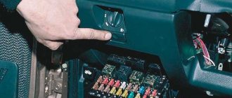
If after turning the ignition key there is no buzzing sound from the fuel pump, then the first thing to check is the fuel pump fuse and relay. In the Lada Kalina and Lada Granta mounting block, the fuel pump fuse is F21 (15A), and the fuel pump relay is K12. If the fuse is good, do the following:
- Turn on the ignition
- Remove the fuel pump relay
- Apply +12V to pin No. 11 of the diagnostic block, or place a jumper between 87 and 30 relay pins
- Check by ear that the fuel pump is turned on
If the fuel pump does not turn off, then check:
- Wiring and contacts between the fuel pump and the diagnostic block/fuel pump relay. To do this, check the voltage at the fuel pump chip using a test lamp or multimeter.
- There is no connection between the fuel pump and the vehicle ground. Apply the mixture to the fuel pump (located under the rear seat).
- The fuel pump is faulty. To check it, apply +12V directly to the contacts of the fuel pump (Attention! Remaining gasoline may ignite from a spark!).
In rare cases, the fuel pump does not work due to:
- ECU (controller) malfunction
- alarm malfunctions
Possible causes of fuel supply system failure
The fuel pump on Kalina is electric. The use of this design and operating principle is justified by a number of advantages. These are simplicity and reliability, compliance with the required characteristics in terms of fuel supply volumes and a high level of safety ensured by turning off the system when the engine stops running.
On the other hand, for high-quality work you need excellent gasoline and cooling of the fuel pump, and the process is also accompanied by an increased noise level.
- As a rule, poor quality gasoline and dirty filters lead to incorrect operation of the gasoline pump or its failure.
- If there is no response from the engine when you turn the ignition key, the problem may be due to a broken fuel pump.
- Since the main unit of the fuel system is powered by current, to troubleshoot it is necessary to check the electrical circuit going to the fuel pump.
Checking the fuel pump Lada Priora
On the Lada Priora, the fuel pump relay and its fuse are located in an additional mounting block near the left foot of the front passenger. The fuse is marked F3 (15A), and the relay is K2.
First of all, we check the fuel pump fuse, and if necessary, replace it with a similar new one. We check the wiring and the fuel pump itself in the same way as on Lada Kalina and Lada Granta cars (see above).
As a reminder, don't forget to change your fuel filter regularly.
Schematic electrical diagrams, connecting devices and pinouts of connectors
The fuel pump on a car is designed to supply fuel to the combustion chamber. Its operation is controlled using a relay. On a VAZ (depending on the model), the fuel supply unit can be electrical or mechanical - it all depends on the fuel supply system. On a fuel-injected car, the fuel pump is located in the tank. When the ignition is turned on, voltage is supplied to the terminals of the unit and it begins to pump fuel. If the required pressure is created in the system, the relay automatically turns off the fuel pump - the engine is ready to start.
When the ignition is turned on, the relay creates pressure in the fuel lines by turning on the fuel pump (BN) for a couple of seconds. After this, the BN will work either when the engine is cranked by the starter, or when the engine is running.
Sometimes this system needs repairs - there is nothing complicated here, and the editors of the 2Skhema.ru website will tell you how to do it yourself. Let's start with the BN pinout, then we will indicate it on the diagrams and at the end there will be instructions for replacing the fuel supply elements.
Algorithm for checking a fuel pump using a tester:
Stage 1 – checking the fuse and relay. Stage 2 – checking the voltage at the relay input. Stage 3 – checking the voltage at the relay output. Stage 4 – checking the voltage on the fuel pump block.
The Lada-Kalina submersible fuel pump, as in other cars, is necessary to supply gasoline to the combustion chamber of the internal combustion engine. The pump is activated immediately when the ignition is turned on and maintains operating pressure until the car is turned off or the fuel runs out. The fuel pump is part of a module that includes a fuel pressure regulator, which changes the supply parameters when the driver operates the accelerator pedal. The module also contains a sensor that sends data to the dashboard, to the fuel level indicator. In addition, the design of the fuel filter includes a fine-mesh mesh for coarse fuel cleaning.
The manufacturer declared the resource of the fuel pump on Lada Kalina to be 160 thousand kilometers. The most common model of the unit is a Bosch submersible rotary fuel pump. This is available in online stores for approximately 2,500 rubles.
- Reasons why the fuel pump does not pump gasoline when the ignition is turned on
Content
Pinout of fuel pump VAZ 2107
1 – radiator fan drive motor; 2 – mounting block block; 3 — idle speed sensor; 4 – engine ECU; 5 – potentiometer; 6 – set of spark plugs; 7 – ignition control unit; 8 – electronic crankshaft position sensor; 9 – electric fuel pump; 10 – indicator of the number of revolutions; 11 – lamp for monitoring the health of electronic systems and the brake system; 12 – ignition system control relay; 13 – speedometer sensor; 14 – special factory connector for reading errors using the BC; 15 – injector harness; 16 – adsorber solenoid valve; 17, 18, 19,20 – fuse box for repairing the mounting block that protects the injection system circuits; 21 – electronic fuel pump control relay; 22 – electronic relay for controlling the exhaust manifold heating system; 23 – exhaust manifold heating system; 24 – fuse protecting the heater circuit; 25 – electronic air sensor; 26 – coolant temperature control sensor; 27 – electronic air damper sensor; 28 – air temperature sensor; 29 – pressure control sensor and low oil pressure lamp.
You can check the fuel pump on a VAZ 2107 simply by checking the voltage at its connection block with a tester. The presence of voltage will indicate a malfunction of the electric motor. Instead of a tester (multimeter), you can use a test lamp to diagnose a malfunction.
In the absence of one, this can be done by disconnecting the connection block for the fuel pump and fuel level control and applying voltage with wires from the battery to the place where the gray wire is connected +12 and to the place where the black wire is connected - minus. A humming pump will indicate a faulty fuse, power circuit or ECU.
Connector block for fuel pump 2110 new. (thick)
Leave your review of the product: Connector block for fuel pump 2110 new. (thick)
Delivery to regions
- Delivery of goods is paid upon receipt of the goods in your city.
- Delivery to the transport company is FREE
- The timing, cost and method of delivery by region depend on the weight, dimensions and cost of the ordered product.
Attention: Orders are processed every day, seven days a week, from 09-00 to 21-00 inclusive
Order of shipment to regions of the Russian Federation.
- Place an order through the website or by phone.
- You pay the bill through the bank, after the money arrives in our bank account (usually 1-3 days after payment for the goods), when paying through electronic money systems (funds are credited within a day), we deliver the goods to the transport company.
You can make a preliminary calculation of the cost and delivery time of the goods you have chosen to your city by choosing one of the companies recommended by us.
Russian PostPhone: 8-800-2005-888 Website: https://www.russianpost.ru Coverage: delivery is possible to any location in Russia Opening hours: Mon-Fri from 10 to 19, Sat from 11 to 16, Sun – closed Calculate delivery cost Track the cargo
Business linesPhoneSite: https://www.dellin.ruCoverage: 500 cities of RussiaOperating hours: Mon-Fri from 10 to 19, Sat from 11 to 16, Sun - closedCalculate delivery costTrack the cargo
Attention - This delivery method is ordered from a consultant! Phone Website: https://www.emspost.ru Coverage: delivery is possible to any location in Russia Opening hours: Mon-Fri from 10 to 19, Sat from 11 to 16, Sun – closed Calculate delivery cost Track the cargo
PECTphoneSite: https://www.pecom.ru Opening hours: Mon-Fri from 8 to 20 Sat from 10 to 16, Sun – closed Calculate delivery cost Track cargo
SDEKTelephoneWebsite: https://www.edostavka.ru/Opening hours: Mon-Fri from 8:30 to 19, Sat from 10 to 16, Sun – closed Calculate delivery cost Track cargo
Hermes. You can pick up your parcel yourself at one of the Hermes delivery points in 196 cities of Russia. Hermes points are located within walking distance from the metro and public transport stops. Website: www.hermesrussia.ru Opening hours: Mon-Fri from 9-00 to 19, Sat from 10 to 16, Sun – closed
If you cannot decide on the choice of transport company or do not know which transport companies deliver goods to your city, we will be happy to advise you.
If you cooperate with a transport company not represented in this list, then write to us and we will deliver your cargo to any transport center within the city of Tolyatti.
Pinout BN VAZ 2108, 2109, 21099
The fuel pump activation relay (2) is shown by an arrow.
1 — nozzles; 2 — spark plugs; 3 — ignition module; 4 — diagnostic block; 5 - controller; 6 — block connected to the instrument panel harness; 7 - main relay; 8 - main relay fuse; 9 — electric fan relay; 10 — controller power supply fuse; 11- electric fuel pump relay; 12 — fuel pump power circuit fuse; 13 — mass air flow sensor; 14 — throttle position sensor; 15 — coolant temperature sensor; 16 — idle speed regulator; 17 — knock sensor; 18 — crankshaft position sensor; 19- oxygen sensor; 20- APS control unit; 21 — APS status indicator; 22 — speed sensor; 23 — electric fuel pump with fuel level sensor; 24 — solenoid valve for purge of the adsorber; 25 — block connected to the ignition system harness; 26 — instrument cluster; 27 — ignition relay; 28 — ignition switch; 29 — mounting block; 30 — electric fan of the cooling system;
Fuel pump repair on Kalina
Hospitality! Fuel pump - in general, the fuel pump cannot be repaired and is immediately replaced, but in this article we will talk to you not about the fuel pump itself (this is its second name), but about repairing the fuel module, which includes the fuel pump itself, as well as fuel level sensor and fuel pressure regulator (there are some more details about the module, but we will not describe them all, since you are reading the article, you will encounter them anyway, so there is simply no point in talking about them again).
Note! To repair the fuel module you will need tools, namely: pliers and a set of screwdrivers, nothing else is needed, but this is as long as the fuel module itself has already been removed from the car, if you just need to remove it, then a hammer and hammer drill, which would also need to be replenished (if not, then you can do without it; a screwdriver, by the way, can also replace it)!
- Fuel pump repair
- Additional video clip
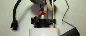
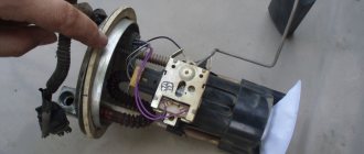
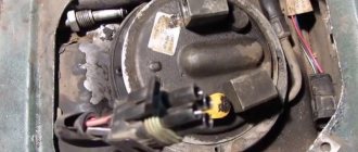
Where is the fuel pump located? The fuel module itself is located inside the gas tank, if you remove it and at the same time remove the glass from the module (you will learn more about how to do this when reading the article, there will be pictures), then you will have access to all the parts of the fuel module (all details refer to the pump itself, as well as to the grid, fuel pressure regulator, and so on), for clarity, we have placed a photo below, where the glass has already been removed from the module and the red arrow points to the fuel pump itself, which is located inside the housing.
When does a fuel pump need to be repaired? Once the car has stopped moving and the pump begins to make a lot of noise (you will immediately recognize this noise when the engine is running), and the car may still be shaking, this indicates that the pump has become unusable and needs to be replaced (but it may also be the fuel filter or the network of fuel modules is clogged, in this case the car will work the same as if the fuel pump fails), as well as the fuel level sensor, which is present on the fuel module, and if it fails, the fuel level indicator located on the instrument panel, it will begin to incorrectly show the remaining gasoline in the tank (for example, the indicator needle may drop completely and show nothing), in addition, there is also a fuel pressure regulator on the module, and in case of failure, the car may also begin to move poorly and start up just as poorly , the next part present on the fuel module is the fuel purification mesh, which goes into the car engine (this setting is scientifically called the primary fuel filter), becomes clogged over time and requires replacement (there is a new one-dimensional mesh) or, if not , you have stores where it is sold or you just feel sorry for the money, then you can still wash it, you won’t wash off all the dirt, but it will be much better, so if it fails, the pump itself must work for wear and tear (with all its power) and therefore, soon, because of this mesh, the fuel pump itself will become unusable, the symptoms of a clogged mesh are exactly the same as when the pump malfunctions, that is, it starts to make noise (because you have to work hard), the car starts to drive poorly, as if it’s stalling (but it’s not stalling) , this is completely different, you can just have a contract) and so on
How to repair a fuel pump on a VAZ 1117-VAZ 1119?
Disassembly: 1) Before you begin the repair, you will need to remove it from the car, all this is done in the order of 10-15 minutes, if you have already removed it earlier, you will do it in 5 minutes, read more about how to remove the fuel pump from the car, read the article entitled: “Replacing the fuel pump on a car.”
2) Now let's proceed to the disassembly itself, first you will need to disconnect the exhaust pipe from the fuel module with a screwdriver (see Photo 1), to do this, pry it off with a screwdriver and then disconnect it, then grab the body of the fuel module itself with your hand and move it until it stops (you don’t need to apply too much a lot of effort), among other things, before lifting it completely, remove the retaining ring from one of the guides using a screwdriver (the ring is marked with an arrow in photo 2), just removed and the body will point completely upward, disconnect the cable terminal from pressure regulator (see photo 3), and then use a screwdriver to tighten the clamp securing the terminal block (see photo 4) and then disconnect the terminal block from the intermediate connector.
3) Let's go a little further and now you will need to disconnect the second block of wires (see Photo 1), this block is connected to the fuel pump itself and before pulling it you will need to press the latch that secures it, then use two side fastening clamps to unlock the level sensor fuel (see photo 2) and move the sensor up, remove it, after which you need to remove the fuel pressure regulator, it is fixed with a spring clip, which can be removed from the slot with a screwdriver (see photo 3) and then the sensor itself can be removed (see photo 4) .
Note! When the fuel level sensor is removed, wash the rheostat slider plate and rheostat contacts with gasoline (to understand where the rheostat sensor is located, we indicated it with a blue arrow in the second photo above), after washing, wipe the rheostat with a rag soaked in alcohol or a lint-free rag soaked in alcohol and dirt, by the way, also check the fuel pressure regulator, that is, look at its sealing rings (the rings are right on it, they are rubber, you will find them right away), which must not be torn, cracked or simply deformed, if necessary, remove them manually or with a screwdriver and replace with new ones!
4) Well, at the end of the operation, remove the fuel module up along the guides, but before removing it, squeeze all the fixing clips of the module (see Photo 1, they need to be folded like latches) and only then disconnect the glass module, then remove the mesh from the bottom of the module (to do this, use a screwdriver to lift it from below and, using the screwdriver as a lever, turn off the network, see photo 2 for more details), which cleans the fuel supplied to the car engine, if necessary, replace it with a new one or simply rinse the old one thoroughly with gasoline (it is recommended however, replace it, you never wash off all the dirt with the old one), So when you put the mesh back on, be sure to remove the safety washer that secures and straightens it (see photo 3, just when the mesh is removed, this washer bends for this reason, the grid is not sufficiently attached, since it must be effectively connected), and later the network can be reinstalled, but if it is necessary to replace the fuel pump itself with a new one, then after disassembling the module, tighten the plastic clamp and then remove the pump from the housing in which it is located (see photo 4) and replace it with a new one.
Assembly: The entire assembly is performed in the reverse order of removal, and the fuel module is returned to its place in the same reverse order, but there are some nuances during installation, so for more detailed information on installation, please read the article: “Replacing the fuel pump on a VAZ ", a link to this article, which we already provided and you followed, it describes in detail the installation.
Additional video: if you want to see with your own eyes the whole process of disassembling the pump, in this case, watch the video that we posted just below, using the example of the fuel module of a VAZ 2115 car (Still made at Kalina), everything is clearly shown.
1200 rubles for a photo report
We pay for photo reports on car repairs. Earnings from 10,000 rubles. / Month Write:
The reasons why fuel pumps fail are not always the same, and the devices themselves can be electrical or mechanical. Diagnostics of the performance of these types is different, so we will consider ways to separately check the operation of fuel pumps. However, the operation of the fuel pump can be checked in 7 steps.
The need to check the fuel injection pump appears when the following signs of malfunction occur:
- the engine stopped;
- the car moves chaotically, jerkily;
- the engine idles unstable and does not start;
- there are “floating” turns;
- increased noise, whistling when the car is moving.
VAZ 2110 fuel pump pinout
If the fuel pump works directly when connected to the battery, then you will have to ring the wires going from it to the fuel pump relay, and if it does not work, then either replace it with a new one, or you will have to disassemble it and look for a fault inside the fuel pump.
How to check the fuel pump yourself
| The car won't start, can't you hear the fuel pump running when you turn the ignition key? Don’t rush to replace it with a new one; it’s better to first understand how to check the operation of the fuel pump yourself. |
Procedure: 1. Check the fuel pump fuse. This is where you should start checking the fuel pump. On the VAZ 2110 it is located near the left foot of the front passenger.
2. How to check the fuel pump relay. The relay is located next to the fuse, so let's check it right away. We check the voltage at the control terminals one by one (87, 86 and 85 in turn), touching the other end to the ground. The test instrument can be a multimeter or a test lamp with a current consumption of no more than 0.25 A. If the lamp does not light and the fuse is good, we check the wiring and condition of the computer. Sometimes they control differently, for example, instead of a relay, a test lamp is connected between pins 85 and 86. When the ignition is turned on, the light should be on. You can also place a jumper between pins 87 and 30. Does the fuel pump start running when you turn the key? This means the relay is faulty. You can also test the fuel pump relay by replacing it with a known good one. 3. How to check if the fuel pump is working properly. Without removing it, we check the voltage on its microcircuit using a test lamp or multimeter.
Pinout BN VAZ 2113, 2114, 2115
— block headlights; — gearmotors for headlight cleaners*; - fog lights*; — ambient temperature sensor; - sound signals; — engine compartment lamp switch; — electric motor of the engine cooling system fan; — generator; — low oil level indicator sensor; — washer fluid level sensor; — front brake pad wear sensor; — wire tips connected to the common windshield washer pump**; — windshield washer pump; — headlight washer pump*; — wire ends for connecting to the rear window washer pump on VAZ-2113 and VAZ-2114 cars; — low oil pressure indicator sensor; — engine compartment lighting lamp; — wire lug for connecting to the wiring harness of the engine control system; — gear motor for windshield wiper; — starter; — a block connected to the wiring harness of the ignition system on carburetor cars; — coolant temperature indicator sensor; — reversing light switch; — low brake fluid level indicator sensor; - accumulator battery; — low coolant level indicator sensor; — relay for turning on fog lights; - mounting block; — brake light switch; — plug socket for a portable lamp; — hydrocorrector scale illumination lamp; — switch for the parking brake indicator lamp; — block for connecting a backlight lamp; — switch for instrument lighting lamps; - Understeering's shifter; - hazard warning switch; — front seat heating element relay; — ignition switch; — rear fog light circuit fuse; - fuse for the front seat heating elements; — door lock circuit fuse; — front ashtray illumination lamp; — ignition relay; - cigarette lighter; — glove box lighting lamp; — switch for the glove compartment lighting lamp; — heater fan electric motor; — additional resistor for the heater electric motor; — heater fan switch; - heater switch illumination lamp; — lamp for illuminating the heater levers; — gear motors for electric windows of the front doors; — power window switch for the right front door (located in the right door); — gear motors for locking front door locks; — wires for connecting to the right front speaker; — gearmotors for locking rear doors; — wires for connecting to the right rear speaker; — door lock control unit; — wires for connection to radio equipment; — headlight cleaner switch*; — rear window heating element switch; — relay for turning on the rear fog lights; — block for connection to the heating element of the right front seat; — rear fog light switch; — switch for the heating element of the right front seat; — fog light switch*; — switch for external lighting lamps; — left front seat heating element switch; — block for connection to the heating element of the left front seat; — wires for connecting to the left front speaker; — power window switch for the left front door (located in the left door); — power window switch for the right front door (located in the left door); — wires for connecting to the left rear speaker; — side direction indicators; — courtesy light switches on the front door pillars; — courtesy light switches on the rear door pillars; - lampshade; — ceiling lamp for individual interior lighting; — block for connecting to the wiring harness of the electric fuel pump; — trunk light switch; — instrument cluster; — trunk lighting lamp; — display unit of the on-board control system; - trip computer*; — block for connecting the wiring harness of the engine control system; — rear exterior lights; — rear interior lights; — pads for connecting to the rear window heating element; — license plate lights; — additional brake signal located on the spoiler.
What happens if you turn off the lambda probe? we tell and show
There are quite a lot of different sensors in a modern car, the purpose of which many drivers do not know.
Therefore, the question of what will happen if the lambda probe is turned off is not uncommon. This sensor is quite sophisticated, unlike the device that monitors the position of the crankshaft, as well as other similar sensors. The lambda probe has a scary name. That is why many car enthusiasts consider this sensor completely useless, while others consider it the source of all troubles. Let's try to figure out who is right in relation to this probe. After all, in fact, this is a very important detail, but it must be guaranteed to be in good working order.
How does it work? What happens if you turn off the lambda probe? Before answering this question, you need to understand how it works. The main function is to control the operation of the catalyst. More precisely, the purpose depends on the location of this sensor.
The most common option is to install a probe in front of the catalyst. In this case, it controls the amount of oxygen in the mixture. If necessary, it sends a signal to the control unit, forcing it to increase or decrease the amount of oxygen in the mixture.
Also, a lambda probe is often installed after the catalyst. In this case, he checks the composition of the exhaust gases. If the level of toxic substances is high, a signal is sent to the control unit. As a result, the “check” lights up; computer diagnostics can indicate that the catalyst is faulty.
This sensor is called after the Greek letter? (lambda). This is how physics denotes the ratio of the volume of oxygen to the bulk of the fuel in the combustible mixture. The normal indicator is ?=14.7 per unit of fuel. If this indicator is lower or less, the sensor gives a command to the control unit to change the ratio.
Types of sensors All probes are completely identical in principle of operation. All the differences lie in the features of the power supply connection. In practice, they are usually distinguished by the number of wires that are connected to the probe. The most common are two- and three-pin sensors.
There are also options with and without heating. Heated sensors are more effective when starting the engine in winter, they show better results. If necessary, both types of probes are interchangeable. You can also install a sensor from any car, even with a different number of wires. Only in this case will you have to tinker with the connection.
Is it possible to drive without this sensor? In fact, in most cases, the car can be operated if the lambda probe fails; only on some models, if the lambda probe fails, it will be impossible to start the engine. Here another question arises, how effective and useful this will be.
The first sign of failure is increased fuel consumption. This is due to the incorrect reaction of the control unit to the current situation. Also, usually the car starts to become “stupid”; this is also a consequence of problems with the probe (see the article “Why does the car become dull when accelerating”).
As you can see, driving a car is possible in most cases. But, at the same time, you will have to come to terms with increased fuel consumption. Also, driving a car turns out to be quite difficult due to low throttle response. If you disconnect a working probe, problems with engine operation will arise. The machine will not respond to the disconnection of a faulty sensor.
Diagnostics Often, completely different breakdowns are mistaken for a lambda probe failure. Therefore, before purchasing a new sensor (it costs a lot), you should definitely carry out diagnostics. The best option is to use a diagnostic scanner.
The computer usually shows if there is a lambda probe error. In some cases, there is a complex of problems; in addition to the oxygen sensor, some other parts of the car also fail. There is also a “collective farm” diagnostic method. It consists of turning off the sensor and checking how the car will work without it.
It is believed that if the probe is in working order, its disconnection will lead to deterioration in engine performance or the inability to start it. If the sensor is faulty, there will be no changes. Unfortunately, this diagnostic method is not always reliable; it is better to carry out computer diagnostics.
Causes of failure. Low quality fuel often damages this sensor. Lead particles settle on the probe and reduce its sensitivity. In this case, it starts working “every time”. Mechanical damage is also common. Damage to the housing and windings is usually observed.
This happens due to natural wear and tear. Conclusion. A modern car is literally stuffed with various sensors that control its operation. Drivers often wonder what will happen if they turn off the lambda probe. The answer here is as simple as possible: if this sensor is working properly, then there will be a noticeable deterioration in the performance of the motor; if the probe is faulty, you will not notice any changes.
Replacing an electric fuel pump on a VAZ
- Reduce pressure in the fuel supply system.
- Using the fuel supply hose tip clamp, disconnect 2 hoses in turn.
- Unscrew the 8 nuts around the circumference of the clamping ring and remove it.
- A wire with negative polarity is attached to one of the nuts; it must be removed carefully.
- We take the electric pump block out of the fuel tank, tilting it slightly, to keep the fuel level indicator sensor lever intact, otherwise it will produce incorrect parameters.
- Remove the sealing rubber ring of the fuel block. If its properties are lost, the product must be replaced.
- Install the pump in reverse order.
When installing fuel hoses, focus on the direction of fuel supply indicated by the arrows, and the installation arrow on the electric pump cover should point towards the rear of the car!
Replacing the fuel pump Kalina
Before replacement, read the operating manual to learn the location of the fuel system element, the specifics of the adjacent fuel lines and the types of fasteners. When working, it is important to follow the outlined algorithm so as not to disrupt the functioning of the fuel supply system. Damage to the fuel line or improper assembly of the fuel module can lead to engine damage and even a car fire.
To carry out the work, the car owner will need:
- pliers;
- hammer;
- screwdrivers for flat and Phillips slots.
Sequence of replacing the fuel pump Lada Kalina
Before starting work, you need to “de-energize” the Kalina by disconnecting the battery terminals. Repair procedures should be carried out away from fire and places where sparks could be generated.
- We dismantle the rear seat and floor trim;
- Under the seat there is a fuel tank cap secured with 4 “cross” bolts. Unscrew;
- Now the car owner has access to the top cover of the fuel pump;
- Now you need to “unhook” all the plugs and fittings from the pump. To remove the power plug, press the latch upward and pull the plug to the side. The power plug itself is located on the left side of the fuel pump cover;
- To remove the fittings, you must use pliers. The locking clamp is pressed out by hand, after which the fitting itself is removed using pliers. The main thing is not to confuse the fittings: the lock on the top is green, the lock on the bottom is metal;
- After dismantling the fittings, clean the fuel pump cover as much as possible - dirt will not get into the gas tank;
- Removing the fuel pump cover retaining ring: take a flat-head screwdriver, place it against the outline of the ring and lightly tap it with a hammer so that the ring moves clockwise. The latch should pop out and the cover will be accessible;
- Open the cover and carefully pull the pump up so as not to damage the adjacent elements. Additionally, make sure that no sand gets into the tank;
- We take the new pump and carefully immerse it in the technological hole. We attach the lid. Next, assembly is carried out in reverse order.
After the repair, you need to start the Kalina and drive for a few minutes. During operation, it is necessary to check the operation of the internal combustion engine in different speed ranges, at idle speed; You also need to be attentive to various noises in the fuel tank.
The Kalina fuel pump relay is an important element for ensuring stable operation of the car. The internal combustion engine is the main unit for the movement of road transport. With the advent of electric vehicles, the share of cars with internal combustion engines is decreasing, but the vast majority will be provided with cars powered by hydrocarbon raw materials for the coming decades.
For stable operation of the flaming engine of any car, including the Lada Kalina, a stable supply of a sufficient amount of fuel is necessary.
The main element of the fuel system on Kalina is the fuel pump. The fuel tank on the Lada Kalina is located in the rear of the body, therefore, the delivery of gasoline through the supply pipes to the injector sprinklers must be constant and forced.
Other elements of the car's fuel system, in addition to the tank and fuel pump, are a fine filter and fuel supply pipes.
Where is the fuel pump relay located?
Where is the fuel pump relay located? The installation location of the relay varies depending on the make of the car. Most often, it is located under the hood, in the fuse and relay box.
The fuel pump relay is designed in the circuit to prevent accidental application of high voltage to the fuel pump winding. The relay is standard and consists of a plastic body and coils with contacts. It is located in the car interior near the console. To access it, you need to remove the protection cover.
In appearance, it is a small box that resembles a “plug” with an American type of output. Each terminal has a marking that indicates the following: 31 – mass; 30– +12V constant (regardless of ignition); 15– +12 with the ignition on; 50– +12 when the starter is running; TD – signal from the ignition system; TF – engine temperature signal from the injection control unit KE. Outputs: 87 – supplies power to the fuel pump; 87H – oxygen sensor heating; 87V – turns on the starting injector.
But sometimes the fuel pump does not turn on when the key is turned in the ignition. With what it can be connected? First of all, the fuse, although if it had blown, it would not work at all. Maybe the contact is bad?
If the electric fuel pump does not show any signs of life when the ignition is turned on, this does not mean that it has burned out. The cause of the malfunction may also be a relay. The easiest way to test your hearing is that when you turn on the ignition, the relay should click. If you don’t hear a click, there is a high probability that the “relay” is faulty.
It’s easy to check the functionality of the pump itself, so we do this:
- remove the protective casing, under which there is a block with relays and fuses;
- we unscrew the fastenings of the block, remove it, it remains attached to the wires;
- we pull the RB out of the block, place a jumper between two opposite contacts, thus directly supplying power to the BN;
- if with such a connection the electric motor of the pump begins to make noise, it means that the BN itself is working, most likely the fault is hidden in the relay;
- if there is no voltage on any of the contacts on the RB block, you should look for a break in the wiring; there may also be poor contact at the place where the wire is attached to the terminal.
Troubleshooting the Kalina fuel pump
If the electrics are working correctly, the fuel pump remains the object of close study. Replacing the fuel pump assembly is an extreme, and not at all mandatory, measure.
Electrical diagram for connecting a fuel pump
If the fuel pump does not turn on during normal electrical operation, remove the device to check the fuel pump. To check the functionality of the fuel pump, you need to remove the cover, which is located in the rear of the car, and remove the unit itself.
If the pump does not pump or pumps intermittently, it may be necessary to replace the Kalina fuel pump mesh. We remove the cover, disconnect the hoses and wires, use screwdrivers to press out the retaining ring and gain access to the pump. The device itself is located in the gas tank and takes gasoline directly from the tank.
Routine work, which would include replacing the mesh, is not specified in the operating instructions for the Lada Kalina. Repairing the fuel pump in order to replace the mesh should usually be carried out after 50 thousand kilometers, since the fuel at Russian gas stations is generally of low quality.
During dismantling, this can be assessed visually; the mesh turns from white to dirty brown interspersed with mechanical residues of metal, dirt and oil. At the bottom of the glass, when dismantled, you can see solid particles of unknown origin, which could only get into the tank when refueling.
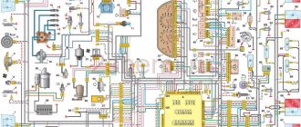
General diagram of electrical equipment of VAZ 1118
1 — block headlight; 2 — windshield wiper gear motor; 3 - generator; 4 - battery; 5 - starter; 6 — sound signal; 7 — hood open sensor; 8 — power window switch for the right front door; 9 — motor-reducer for window lifter of the right front door; 10 — electric pump for windshield washer; 11 — connecting blocks of wires for connecting the right (front) speaker of the audio system; 12 — electric drive for locking the lock of the right front door with an open door sensor; 13 — ambient air temperature sensor; 14 — connecting block of the wiring harness for connection to the engine control system harness; 15 — electric drive for locking the left front door lock (with an open door sensor and a central locking switch); 16 — sensor of insufficient brake fluid level; 17 — connecting blocks of wires for connecting the left (front) speaker of the audio system; 18 — right front door power window switch (installed on the driver’s door); 19 — left front door power window switch; 20 — central locking switch; 21 — motor-reducer for window lifter of the right front door; 22 — remote control unit; 23 — immobilizer control unit (APS-6); 24 — mounting block; 25 — instrument panel; 26 — right side turn signal; 27 — glove box lighting lamp; 28 — switch for the glove compartment lighting lamp; 29 — brake signal switch; 30 — ignition switch (lock); 31 — lighting control unit; 32 — steering column switches; 33 — left side direction indicator; 34 — connecting blocks of wires for connecting the left (rear) speaker of the audio system; 35 — electric drive for locking the left (rear) door with an open door sensor; 36 — electric heater fan; 37 — additional heater resistor; 38 — heater switch; 39 — alarm switch; 40 — reverse lock solenoid switch; 41 — rear window heating switch; 42 — connecting blocks of wires for connecting the right (rear) speaker of the audio system; 43 — electric drive for locking the right rear door lock (with a door open sensor); 44 — fuel module of the engine control system; 45 — reverse light switch; 46 — parking brake warning lamp switch; 47 — cigarette lighter; 48 — reverse lock solenoid; 49 — connecting blocks of wires for connecting the head unit of the audio system; 50 — backlight lamps on the trim of the center console of the instrument panel; 51 — electric power steering control unit; 52 — interior lamp; 53 — rear light; 54 — block for connecting the electric drive for locking the trunk lid lock*; 55 — luggage compartment lid open sensor; 56 — license plate lights; 57 — additional brake light; 58 — rear window heating element; 59 — luggage compartment lighting lamp.
Connecting a radio to a VAZ-Lada. connection diagrams and videos
In this article we will look at methods and diagrams for connecting car radios to VAZ, Lada cars, the following models: VAZ 2101, 2102, 2103, 2104, 2105, 2106, 2107, 2108, 2109, 21099, 2110, 2111, 2112, 2113, 2114 , 2115, Priora, Kalina, Niva, you can find connection diagrams for newer models at the very beginning of the article devoted to connecting radios to cars of various brands.
So, the diagrams: Standard radio connection diagram for VAZ 2101, 2102, 2103, 2104, 2105, 2106, 2107, Niva
Wiring diagram for a VAZ radio from the ignition switch using a relay
Wiring diagram for a VAZ radio from the ignition switch using a relay (Option 2)
Wiring diagram for a VAZ radio from the ignition switch using a relay (Option 3)
Wiring diagram for a VAZ radio from a button using a relay
The button itself
Wiring diagram for a VAZ radio from an alarm system using a relay
Connection diagram for radio for VAZ 2107 with injector
Radio connection diagram for VAZ 2109, 2109, 21099
Connection diagram for radio for VAZ 2109, 2109, 21099. Pinout of contacts (for all VAZ models)
Connection diagram for a VAZ radio in which: the PG (head unit, radio) is turned on only when the ignition is turned on, when the ignition is turned off, the PG continues to work, when the alarm is armed, the PG turns off
Radio connection diagram for VAZ 2110, 2111, 2112, 2113, 2114, 2115
Radio connection diagram for Lada Kalina, Priora (and Largus)
Radio connection diagram for Lada Kalina, Priora (and Largus). Pinout
A very useful video that discusses in detail the correct connection of the radio, which allows you to avoid loss of battery energy in the inactive mode of the radio, and also provides a visual overview of the connection diagrams from the ignition switch
A video from which you will learn about the purpose of each of the wires, as well as about the correct connection of the radio (additional information to the video above)
Video of connecting the radio for VAZ 2101, 2102, 2103, 2104, 2105, 2106, 2107
Video of connecting the radio for VAZ 2107 injector, 2108, 2109, 21099, 2110, 2111, 2112, 2113, 2114, 2115
Video of installation and connection of a 2 DIN radio for Lada Priora
Detailed diagram for connecting a radio in a car for a VAZ, Lada, with a sound amplifier
Connection diagram of the amplifier from the radio and battery (battery) details of the amplifier settings
Connection diagram for subwoofer and rear from a 4-channel amplifier
Connection diagram for a subwoofer from a 2-channel amplifier
A simple and very clear diagram of connecting speakers or a subwoofer from an amplifier; connecting the amplifier itself to the radio and battery (battery)
Connection diagram for acoustics and subwoofer from sound amplifier
Here you can clearly see how to connect crossovers from an amplifier and acoustics from them
A diagram reminding you that each element has a resistance measured in Ohms, as well as that the sound amplifier should always be more powerful than all the speakers and/or subwoofers connected to it combined
Connection diagram for acoustics from an audio amplifier, which, in turn, is connected from the battery using a capacitor (power storage device)
And here is a more complex diagram for connecting two amplifiers and wiring through a relay
Here, dear friends, our article has come to an end. I hope we were able to cover its topic completely, and you found in it the answers to your questions about connecting the radio to VAZ and LADA cars. Thank you very much for reading this article and we wish you good luck in connecting car speakers, and in everything else too! Connect your acoustics with us! See you on the pages of our website!
Lada Kalina dashboard diagram
1,2,3,4 — blocks of the instrument panel wiring harness to the blocks of the rear wiring harness; 5,6 — blocks of the instrument panel wiring harness to the blocks of the front wiring harness; 7 — block of the instrument panel wiring harness to the block of the wiring harness 8 — block of the instrument panel wiring harness to the block of the front wiring harness; 9 — lighting control module; 10 — ignition switch; 11 — on-board computer mode switch; 12 — windshield wiper switch; 13 — sound signal switch; 14 — light signaling switch; 15 — instrument cluster; 16 — evaporator temperature sensor; 17 — interior air temperature sensor; 18 — air conditioner switch; 19 — controller of the automatic climate control system; 20 — heater damper gearmotor; 21 — rear window heating switch; 22 — alarm switch; 23 — brake signal switch; 24 — cigarette lighter; 25 — electric amplifier control unit; 26,27 — blocks of the instrument panel wiring harness to the radio; 28 — backlight lamp for the heater control panel; 29 — illuminator; 30 — mounting block: 31 — heater electric motor switch; 32 — heater electric motor; 33 — additional resistance of the heater electric motor; 34 — glove box lighting; 35 — glove box lighting switch; 36 — control unit of the APS-6 automobile anti-theft system; 37 — driver airbag module; 38 — passenger airbag module; 39.40 — blocks of the instrument panel wiring harness to the blocks of the ignition system wiring harness.
KZ - additional starter relay; K4 - additional relay; K5 - relay-interrupter for direction indicators and hazard warning lights; K6 - windshield wiper relay; K7 - headlight high beam relay; K8 - sound signal relay; K9 - relay for turning on fog lights; K10 — relay for turning on the heated rear window; K11 — electric seat heating relay; K12 - air conditioning compressor clutch activation relay;
Instrument panel wiring harness - 11186-3724030-20.
Signs of a malfunctioning lambda probe. list and recommendations
Do you want to know the signs of a faulty lambda probe? You've come to the right place. By the way, this unit most often worries the minds of foreign car owners, but first things first. But in general, the essence for which a lambda probe is used is sensing exhaust gases.
European automakers, under the pressure of environmentalists and new bills that require limiting the emission of harmful substances into the atmosphere, are resorting in every possible way to the use of various new units. Most often, these are various neutralizers or catalysts - devices that actively reduce the amount of harmful substances in car exhaust.
Signs of a malfunctioning lambda probe will be easier to understand if you know its structure and operating principle. Catalytic converters are active devices that help deal with harmful substances in the exhaust, but they require constant attention and only work under extremely limited conditions.
Careful monitoring of the quality of the air-fuel mixture entering the engine is also required, otherwise the catalysts will quickly fail. Main functions of the lambda probe As noted above, for a longer service life of the catalysts, strict control over the quality of the air-fuel mixture is necessary.
New Lada: Step-by-step replacement of the Grant alternator belt with your own hands
The lambda probe takes its name from a Greek letter; in the automotive world, this letter marks the coefficient of excess air in the fuel mixture entering the engine. In general, a high-quality fuel mixture consists of 13 components of air and 1 fuel. Here you need to understand one simple thing, returning to the quality of the catalysts.
Catalysts can only operate within a very narrow range of the correct fuel to air ratio. Small deviations render these devices useless. Therefore, it is so important to maintain this proportion to tenths. Now you understand that such accuracy in calculating proportions, tracking processes and catalysts is all the prerogative of foreign cars.
Russian cars are not yet operated within such strict restrictive limits as foreign cars. How does the probe work? Inside the device you can find a galvanic cell consisting of a solid electrolyte inside (zirconium dioxide). Various coatings in the form of conductive materials such as platinum.
Device malfunctions The lambda probe performs a complex controller function in the exhaust cycle. The easiest way to check the quality of operation of the unit is to measure the exhaust gases. This can be done using a special stand at service stations.
If the indicator differs from that declared by the manufacturer, then most likely the lambda probe has died. Typically, the percentage of rejection of harmful substances can reach up to 4%. This problem can be observed on older engines, where the engine itself is already working as hard as it can.
Excess additives appear in the fuel mixture. The catalysts fail to do their job and, as a result, the entire system begins to produce increased amounts of pollutants into the atmosphere. In addition to measuring emissions in the vehicle exhaust, there are indirect signs indicating a probe malfunction.
For example, if you notice a negative change in acceleration dynamics (throttle response has worsened). Also, if the engine starts to stall at idle, the speed jumps, the reason may lie in a broken probe. If you carefully monitor your fuel consumption, an increase in fuel consumption may indicate a known cause. It is recommended to replace the lambda probe on a modern foreign car every 100 thousand km.
Manufacturers note that cars operated in cold conditions without warming up require replacement of the lambda probe much more often than those that are warmed up. This figure can be twice the difference! Therefore, we strongly recommend warming up the car without load, especially if it has been parked for a long time at very low subzero temperatures.
For cleaning, you can use orthophosphoric acid by placing the device in it for 15 minutes or, better yet, lubricating the contaminated area with it. Testing the probe It will not be superfluous if you test the lambda probe of your car at least every 35 thousand km.
If you are taking measurements, remember that the probe needs time to warm up to operating temperature. The signs of a faulty lambda probe listed above will help save time and money. Exhaust gas measurements are carried out at some dealers, and you can also get some recommendations there.
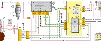
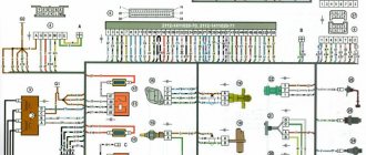
Ignition system diagram Lada Kalina Lux
1 — oil pressure warning lamp sensor; 2 — coolant temperature indicator sensor; 3 — additional fuse block; 4 — fuses for the electric fan of the engine cooling system; 5 — electric fuel pump relay; 6 — relay for the electric fan of the engine cooling system; 7 - ignition relay; 8 — relay 2 of the electric fan of the engine cooling system; 9 — relay 3 of the electric fan of the engine cooling system; 10 — electric fan of the engine cooling system; 11 — throttle position sensor; 12 — idle speed regulator; 13 — coolant temperature sensor; 14 — diagnostic block; 15 — ignition system harness block to the instrument panel harness block; 16 — solenoid valve for purge of the adsorber; 17 — speed sensor; 18 — ignition system harness block to instrument panel harness block 2; 19 — mass air flow sensor; 20 — crankshaft position sensor; 21 — oxygen sensor; 22 - controller; 23 — rough road sensor; 24 — diagnostic oxygen sensor; 25 — ignition coil harness block to the ignition system harness block; 26 — ignition coils: 27 — ignition system harness block to the ignition coil harness block; 28 — spark plugs; 29 — nozzles; 30 - resistor; 31 — air conditioning system pressure sensor; 32 — blocks of the ignition system harness and injector wiring harness; 33 - phase sensor; 34 - knock sensor.
Ignition system wiring harness -11184-3724026-10. Ignition coil wiring harness -1118-3724148-00. Injector wiring harness -11184-3724036. A - to the “plus” terminal of the battery.
Checking the serviceability of the fuel pump on the injector
When you hear a slight hum or a slight hum when you turn the ignition key, this means that the fuel pump is working, pumping gasoline creates pressure in the system. If, when trying to start, there are no such signs of fuel injection pump operation, then we can assume a malfunction of the electrical system, the pump itself or its individual parts. Therefore, let’s look at how you can check the operation of a gas pump using a phased logic chain. From whether the BN is getting power to whether the fuel pump is pumping and if so, how much pressure is being built up at the fuel rail.
Step 1: Checking the fuse
Checking the fuel pump fuse includes checking the integrity of the conductive plate and, if it breaks, replacing it. But if you don't have a new fuse, wrap copper wire around the fuse contacts. If it burns out again, it means the problem may be in the wiring.
Stage 2: Checking the relay
To check the fuel pump relay, remove it from its socket and connect a 12-volt light bulb according to the diagram. If the light is on, then the relay itself is also working properly. Alternatively, you can use a multimeter in ohmmeter mode to measure the resistance of the relay coil winding. One sensor is connected to terminal 85 and the other to 86. The device will indicate an open circuit if the relay is not working.
Make sure that the terminals do not oxidize - this will negatively affect the power supply to the fuel pump motor!
Stage 3. Checking the power supply to the BN
Checking the fuel pump voltage is done using a multimeter. The meter probes in voltmeter mode (0-20 volts) must be connected to the fuel pump power terminals. Turn on the ignition and take readings on the device. 12-12.5 volts is normal operating voltage. If there is voltage, but the pump does not work, check the electric motor.
Stage 4. Checking the fuel pump motor
To prevent failure of the electric motor, we supply 12 volts directly from the battery to the fuel pump terminals. It works: we check its functionality, check the valve, measure the pressure with a pressure gauge. If it doesn’t work, check the coil for a break.
Does the fuel pump not work when voltage is applied to the terminals? We check the stator winding: take a tester (multimeter) and switch it to ohmmeter mode, it should show resistance, otherwise there is a problem with the winding and it needs to be replaced. With resistance readings, the problem may be that the winding is shorted to the fuel pump housing. The tester probe goes to the positive terminal, the second one goes to the body. If it is short, there will be no interruptions.
Step 5. Checking the coarse filter
By disassembling the coarse filter (see Technical documentation for the car) from the fuel pump, you can even visually determine how dirty it is. If there is a large amount of deposits, it is recommended to replace the filter; if the problem occurs on the road, clean it with a brush and gasoline.
Step 6: Check the check valve
The check valve must constantly prevent fluid from flowing in the opposite direction. During operation, its performance decreases, which reduces technical characteristics.
1 way. Checking the check valve involves measuring the pressure with a pressure gauge. It is necessary to connect it to that part of the system that is directly involved in supplying fuel to the internal combustion engine. Pressure readings should not exceed 3 kg/m2 cm. (Relevant for cars). And when the engine is stopped, the pressure should not drop sharply.
Check and clean check valve
method 2. To check the operation of the fuel pump check valve without a pressure gauge, you need to clamp the return line and observe the operation of the engine. If the check valve fails, the internal combustion engine will operate at higher speeds (in the absence of other problems).
method 3. Combine diagnosis and cleaning of the check valve at the same time. Remove and inspect - the unit requiring cleaning is visible to the naked eye. You can also blow out the valve with a dense stream of air, but it is better to pass water under pressure through it. This will combine valve control with valve cleaning. If the valve does not work even after this, it must be replaced.
Step 7. Pressure check
In order for the diagnostics to correctly identify the pressure gauges, it is necessary to reset the initial fuel pressure by turning off the fuel pump fuse.
Check with a pressure gauge how to pump up the fuel pump
How to check a fuel pump with a pressure gauge
You can check the fuel pump with a service pressure gauge as follows: connect the device to the fuel rail. Conclusion: through the edge of the hood to the windshield, where we securely install the device.
We record measures in:
Static position. Turn the ignition key and observe the pressure gauge readings; they should not exceed 3.7 atm.
Dynamics. We turn on third gear (speed about 50 km/h), observing the pressure gauge readings. While driving, if the problem is pressure, the reading will be below 3 atm or above 3.7 atm.
Low fuel system pressure may be due to a fuel leak. The fuel channel will show a pressure drop of less than 1.6 atm. Fault location: fuel injector or regulator.
It is worth noting that despite all the similarities (principle of operation, purpose), the diagnostic methods for a mechanical fuel pump differ and we will consider this in more detail below.