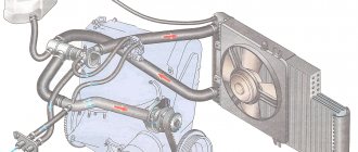
Here are the control diagrams for the VAZ-21120 and 21124 engines. They were installed on Lada hatchbacks of the 2112 family. A diagram of the on-board network is also provided. We are talking about engines containing 16 valves, and the electrical circuit on the VAZ-2112 consists of separate parts: engine control, general circuit. Power supply circuit for headlights, headlights, etc. discussed in the first chapter.
We study in the video how to enable self-diagnosis of the instrument panel to check its operation.
Electrical diagram of a VAZ 2112 car
Electrical diagram of VAZ 2112 - general diagram of connecting electrical equipment and instruments, engine control unit and fuses. When servicing and repairing the engine management system of this and other VAZ family vehicles, always turn off the ignition. When carrying out welding work, disconnect the controller from the wiring harness. The controller contains electronic components that can be damaged by static electricity, so do not touch its terminals with your hands. With the engine running, do not disconnect or adjust electrical connectors.
Where to look for the connector
It is important to know that on different cars the required socket is located in different parts of the car. Moreover, on some AvtoVAZ models it may be in a completely different place compared to another car. Let's look at several VAZ cars as an example:
- on the VAZ-2112, as well as on the 2110, as well as 2111, the socket is located to the right of the driver’s seat, immediately under the column;
- on models 2108, 2109 and 21099, the socket you need is located under the glove compartment, on a special shelf;
- on cars with a europanel it can be found in the center of the console, near the cigarette lighter. A special decorative cover is used to disguise it;
- on Lada Kalina cars, the connector can be found near the gear shift lever. As is the case with cars with a Europanel, it is hidden under a special cover;
- on a Priora you need to look for it right behind the glove compartment, on the wall.
Engine control diagram VAZ 2112
1 - ignition relay; 2 — ignition switch; 3 - battery; 4 - neutralizer; 5 — oxygen concentration sensor; 6 — adsorber with solenoid valve; 7 — air filter; 8 — mass air flow sensor; 9 — idle speed regulator; 10 — throttle position sensor; 11 — throttle assembly; 12 — diagnostic block; 13 — tachometer; 14 — speedometer; 15 — control lamp “CHECK ENGINE”; 16 — immobilizer control unit; 17- ignition module; 18 — nozzle; 19 — fuel pressure regulator; 20 - phase sensor; 21 — coolant temperature sensor; 22 — spark plug; 23 — crankshaft position sensor; 24 — knock sensor; 25 — fuel filter; 26 - controller 2112; 27 — fan switching relay; 28 — electric fan of the cooling system; 29 — relay for turning on the electric fuel pump; 30 — fuel tank; 31 — electric fuel pump with fuel level indicator sensor; 32 — gasoline vapor separator; 33 - gravity valve; 34 - safety valve; 35 — speed sensor VAZ-2112; 36 - two-way valve.
The VAZ-2112 engines and some VAZ-2111 engines are equipped with a distributed phased injection system: fuel is supplied alternately by injectors in accordance with the operating order of the cylinders, which reduces the toxicity of exhaust gases. In this case, a phase sensor is installed on the cylinder head, and a disk with a slot in the rim is installed on the camshaft pulley.
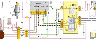
Electrical connection diagram of the ECM Russia-83 Bosch 1.5.4, January 5.1.2 VAZ-21103, 21113, 2112
- — nozzles;
- - spark plug;
- — ignition module;
- — diagnostic block;
- — controller;
- — block connected to the instrument panel harness;
- — main relay;
- — main relay fuse;
- — electric fan relay;
- — controller power supply fuse;
- — electric fuel pump relay;
- — fuse for the power supply circuit of the electric fuel pump;
- — mass air flow sensor;
- — throttle position sensor;
- — coolant temperature sensor;
- — idle speed regulator;
- - knock sensor;
- — crankshaft position sensor;
- — camshaft position sensor (phases);
- — APS control unit;
- — APS status indicator;
- - speed sensor;
- — electric fuel pump with fuel level sensor;
- — oil pressure warning lamp sensor;
- — coolant temperature indicator sensor;
- — oil level sensor;
- - block connected to the ignition system harness;
- — instrument cluster;
- — mounting block;
- — electric cooling system fan;
- — ignition switch;
A - block connected to the ABS cabin group harness; B - block connected to the air conditioner harness; C — block connected to block R of the front harness; D — wire connected to the ignition switch (backlight); E - block connected to the blue-white wires disconnected from the ignition switch; F - to the “+” terminal of the battery; G1, G2 - grounding points; L — contacts of the block to the trip computer; M - contact of the block to the on-board control system unit; N — contacts of the instrument panel harness block and the front harness; R — block connected to block C of the ignition system harness; Z - to the “B+” terminal of the VAZ-2112 car generator.
General information
The car and electricity are fused together from the very beginning. You may recall that the very first such vehicle used an electric motor, until the internal combustion engine was invented.
Wiring a VAZ 2112 makes it possible to perform actions that simply cannot be carried out without electricity.
Among them are:
- ignition of the fuel mixture in the cylinders of a carburetor and injection engine;
- starting the engine;
- operation of head lighting devices at night to illuminate the road surface;
- fog lights when driving in conditions of limited visibility;
- light indication of the instrument scale;
- side lights for vehicle detection at night;
- turn indicators;
- signaling devices.
Schematic diagram of the electrical wiring of a VAZ 2112 car (16 valve)
In addition, the wiring diagram of the VAZ 2112 will help you figure out how and what the auxiliary equipment is connected to:
- “wipers”, which allow the driver to feel normal in rainy or snowy weather;
- sound signals in case of an emergency;
- searching for a spark in case of engine failure;
- CD player and radio;
- window lifters;
- windshield and rear window heaters;
- interior lighting lamps.
The electrical wiring of the VAZ 2112 connects electrical appliances and devices with current sources located in the car. An electrical equipment system is a collection of current consumers and its producers .
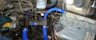
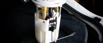
Serviced battery
Car power supplies and ignition
Let's take a closer look at it, starting with the most important elements:
A rechargeable battery is a chemical source of energy, which is a lead-acid DC battery module. The photo shows a battery being serviced. Usually there are six of them.
It is used for:
- starting the engine with an electric starter;
- supplying power to electrical equipment when the engine is not running or when it is running at low crankshaft speeds.
Generator . Used as the main source of current for all electronic and electrical devices and instruments in the car. But, it can provide this only at medium or high crankshaft speeds. The price of this equipment depends on the manufacturer.
Ignition system . Designed to ignite fuel in engine cylinders. Can be contact or non-contact. Modern VAZ 2112 cars are equipped with the latter version, which has a number of advantages over the contact system, which is already considered obsolete.
The main advantages should be noted:
- increased voltage potential supplied to the secondary winding of the ignition coil;
- increased power and longer spark discharge duration;
- increased service life of the spark plug;
- the breaker contacts practically do not fail;
- fuel burns better in the cylinders, which saves money as a result;
- makes engine starting easier;
- the engine becomes more responsive and more economical.
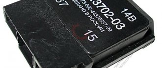
Starter relay installation diagram
If the battery is not charging
When the battery is no longer charged, it does not allow the car to be used for a long time. Maximum until it is completely discharged. In this case, a red light comes on on the instrument panel, which signals that the wiring on the VAZ 2112 requires checking.
The instructions below will help with this:
- Check the generator drive belt, it should be intact and have the required tension.
Advice: it is not recommended to apply too much tension; it will significantly shorten the life of the belt.
- If everything is fine, check the fuse. The VAZ 2112 wiring diagram for 8 or 16 valves, as well as the reverse side of the mounting block cover, will help you find out where it is located. After replacing it and starting the engine, the lamp should go out, allowing you to continue your journey.
Checking and replacing the fuse
- When the charging lamp does not go out, check the wire from the generator to the “+” terminal of the battery. There are usually two of them:
- thick – from the battery to the starter,
- thin - to the generator.
It should not be broken or have oxidized contacts . It happens that there is no way to fix the breakdown, which means that the generator itself needs to be repaired. Repairs must not be delayed as a short circuit may occur. But it’s better to do this at a service station or at home in the garage with your own hands.
Advice: when driving only on battery power, to reduce on-board electricity consumption, turn off as many devices as possible - radio, heater fan, etc.
Fuses and relays 2112
Fuse number Current strength, A Protected circuits
- F1 5 License plate lamps. Instrument lighting lamps. Side light indicator lamp. Trunk light. Left side marker lamps
- F2 7.5 Left headlight (low beam)
- F3 10 Left headlight (high beam)
- F4 10 Right fog lamp
- F5 30 Electric door window motors
- F6 15 Portable lamp
- F7 20 Electric motor of the engine cooling system fan. Sound signal
- F8 20 Rear window heating element. Relay (contacts) for turning on the heated rear window
- F9 20 Recirculation valve. Windshield and headlight cleaners and washers. Relay (coil) for turning on the rear window heating
- F10 20 Reserve
- F11 5 Right side marker lamps
- F12 7.5 Right headlight (low beam)
- F13 10 Right headlight (high beam). High beam warning lamp
- F14 10 Left fog lamp
- F15 20 Electric seat heating. Trunk lock lock
- F16 10 Relay-breaker for direction indicators and hazard warning lights (in emergency mode). Hazard warning lamp
- F17 7.5 Interior lighting lamp. Individual backlight lamp. Ignition switch illumination lamp. Brake light bulbs. Clock (or trip computer)
- F18 25 Glove box lighting lamp. Heater controller. Cigarette lighter
- F19 10 Door locking. Relay for monitoring the health of brake light lamps and side lights. Direction indicators with warning lamps. Reversing lamps. Generator excitation winding. On-board control system display unit. Instrument cluster. Clock (or trip computer)
- F20 7.5 Rear fog lamps VAZ-2112.
- K1 – lamp health monitoring relay;
- K2 – windshield wiper relay;
- K3 – relay-interrupter for direction indicators and hazard warning lights;
- K4 – headlight low beam relay; K5 – headlight high beam relay;
- K6 – additional relay;
- K7 – relay for turning on the heated rear window;
- K8 – backup car relay.
Information that a motorist must know before replacing existing wiring
Replacing wiring VAZ 2110
First of all, the car owner must know when and in what cases the car wiring is replaced. At the same time, it is also necessary to have information about the final operational life in order to objectively understand when the wiring may need to be replaced. List of the most common reasons that cause wiring to malfunction:
- the appearance of cracks in insulation during a long period of operation;
- oxidation;
- corrosion;
- fuse blown, etc.
Components needed to perform wiring replacement:
- multivariate set of wires;
- fuse block for VAZ 21104;
- housing for the heating system;
- various types of sensors: brake fluid, cooling system, etc.;
- pads;
- many terminals;
- Of course, it goes without saying, duct tape.
A practical look at rewiring
Replacing wiring on a VAZ 2110
So, a detailed step-by-step algorithm for replacing the wiring:
- first you need to dismantle the front part of the cabin;
- then you can deal with the proper degree of isolation, if there is a desire for it;
- after which, you need to pay special attention to the front headlight switch;
- The windshield wiper (see Replacing windshield wipers on a VAZ 2110 on your own) operates using its own mini-motor, the wiring of which must be checked for serviceability, since very often it simply becomes acidified;
- understand all heating modes;
- the connection of all electronic devices must be carried out strictly sequentially, by increasing the number of connected wires.
Note. Before disconnecting all electronic devices, it is necessary to draw your own conventional electrical circuit by hand in order to correctly make the appropriate connections in the future.
- now it’s time to tackle the fuse blocks, or rather their installation;
- most wires exceed the required length, so they simply do not fit into the allotted space;
- the bracket is the most rational solution to the problem; it will allow you to successfully replace the fuses with new ones;
- with the installation of a new fuse, the position of the front light indicator light, as well as the emergency warning light, will change;
- the heater will also have to be affected: first you need to remove the old radiator and then disassemble it to make it possible to replace the fan;
- Assembly is carried out strictly in reverse order.
Note. Before you begin the wiring replacement procedure, you need to find its current diagram. Otherwise, during the process of assembly and disassembly, you can quickly get confused, and you will have to send the car to a car service center.
Electrical diagram for VAZ 2110
The main advantages of the new wiring:
- the emergence of a practical opportunity to connect any gadget;
- longer service life compared to old wiring;
- high degree of reliability of everyday functioning;
- improving the quality and stability of electronic devices and much more.
Replacement of electrical wiring of VAZ 2110
It is always necessary to remember that installing homemade wiring is an easily feasible technical manipulation; the main thing is to understand all the necessary nuances.
VAZ-2112 diagram
The VAZ-2112 car was produced at AvtoVAZ from 1998 to 2009, in Ukraine from 2009 to 2014. The following are color wiring diagrams (injector and carburetor) with a description of all elements for various modifications. The information is intended for self-repair of cars. Electrical circuits are divided into several blocks for ease of viewing via a computer or smartphone; there are also circuits in the form of a single picture with a description of the elements - for printing on a printer in one sheet.
To diagnose and repair yourself, first look to see if everything is okay with the generator. Is it put on well and does not sag? This procedure must be done with all versions of the fuel system, both carburetor and injection. We check the fuses according to the electrical diagram. The reverse side of the safety block cover will also be of great help. There are clues there that the diagram will help you decipher. Replace the burnt out element and try to start the car again. You need to check whether the battery terminals are tightly connected and whether they are oxidized. Is the wire going from the battery to the generator and to the starter damaged?
The car does not start - there is no charge in the battery
This problem occurs because the battery charge is going somewhere. It does not disappear by chance, but always for some reason.
Here are some of them:
- you leave the car outside at an ambient temperature of -20 degrees or below;
- the battery life is ending;
- The radio was left on in your car for some time, which led to a loss of charging power.
In all these cases, two types of treatment are usually used: firstly, urgently recharge, and secondly, buy a new battery. If you keep pulling and driving on a dead battery, soon you won't even be able to disarm your car. You will have to manually remove the terminals, trying to make it “silence”. The situation will immediately improve as soon as the battery is charged again.
Modifications of the VAZ-2112 car
VAZ-21120 . Modification with a 16-valve injection engine with a volume of 1.5 liters and a power of 93 horsepower. 14-inch wheels were installed on the car. This modification has a problem with valves bending when the timing belt breaks. The problem can be solved by increasing the depth of the grooves in the piston bottoms.
VAZ-21121 . The car was equipped with a VAZ-21114 8-valve injection engine with a volume of 1.6 liters and a power of 81 horsepower.
VAZ-21122 . Budget modification with an 8-valve injection engine VAZ-2111. The car was produced without electric windows, the wheels were 13 inches in size, and the brakes were unventilated from a VAZ-2108 car.
VAZ-21123 Coupe . Three-door, five-seater hatchback. The only two doors for entering the car are 200 millimeters wider than those of the five-door hatchback, and they are mounted on new, durable hinges. The rear arches of the car have become wider. The engine was installed with a 16-valve injection engine with a volume of 1.6 liters and a power of 90 horsepower. The car was produced from 2002 to 2006 in small quantities, the reason for this was the high cost of the car.
VAZ-21124 . Modification with a 16-valve injection engine VAZ-21124 with a volume of 1.6 liters. Produced from 2004 to 2008. For this type of engine, the problem with valve bending was solved. To do this, the depth of the grooves in the piston heads was increased (up to 6.5 mm). In addition, the design of the cylinder block was changed to achieve a working volume of 1.6 liters, for which its height was increased by 2.3 mm, and the radius of the crankshaft was increased by 2.3 mm accordingly. There were also a number of other minor changes.
Pinout
Knowledge of pinouts may be required if a car enthusiast wants to make an adapter for computer diagnostics with his own hands, or if you need to connect without one. Experts recommend buying ready-made devices without the need to make a plug yourself. However, if you do not have such an opportunity, and diagnostics need to be carried out urgently, we will consider two main pinout options used on VAZ cars of various years of manufacture. Until 2002, AvtoVAZ products used the following pinout option:
- The 4th and 5th pins are GND outputs.
- Pin 16 – +12 V (power line).
- The 7th contact is the diagnostic line itself.
Since 2002, the pinout scheme has changed significantly. Now it looks like this:
- Pin H – +12 V (power line).
- Contact G – +12 V for the fuel pump.
- Pin A – GND output.
- Contact M – diagnostic line.
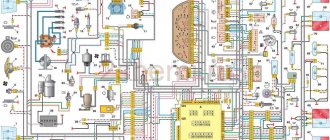
Electrical diagram of VAZ-2112
Designations: 1 – Headlight, 2 – Klaxon, 3 – Main radiator fan, 4 – Starter, 5 – Battery, 6 – Generator 2112, 7 – Gearbox limit switch (reverse), 8 – Actuator in the front passenger door, 9 – Power window enable relay, 10 – Starter relay, 11 – Heater fan, 12 – Electric heater partition drive, 13 – Main pump, 14 – Washer reservoir sensor, 15 – Driver’s door actuator, 16 – Front passenger window selector, 17 – Unlock button fifth door, 18 – Heater fan resistance unit, 19 – Main wiper motor, 20 – Driver’s window lift selector, 21 – Front passenger’s window lift motor, 22 – Central locking, 23 – Exterior light switch, 24 – Brake fluid leakage sensor, 25 – Pump additional, 26 – Driver's window lift motor, 27 – PTF on indicator, 28 – PTF switch, 29 – Dashboard, 30 – Heated glass on indicator, 31 – Heated glass switch, 32 – Steering column selector switch, 33 – PTF relay, 34 – Ignition switch, 35 – Main fuse block, 36 – Illumination of heater controls, 37 – Hazard warning button, 38 – Heater control controller, 39 – Glove compartment lighting, 40 – Glove compartment lid end cap, 41 – Cigarette lighter, 42 – BSK – display unit, 43 – Ashtray illumination, 44 – 12V socket, 45 – Instrument lighting switch, 46 – Actuator in the right rear door, 47 – Right rear passenger window selector, 48 – Clock, 49 – Right rear passenger window motor, 50 – Brake limit switch (closed – pedal is pressed), 51 – Left rear passenger window motor, 52 – Left rear passenger window selector, 53 – Actuator in the left rear door, 54 – Turn signal, 55 – Handbrake limit switch (closed – handbrake on), 56 – Rear wiper motor , 57 – Navigator's lamp, 58 – Interior lamp, 59 – Temperature sensor in the heater, 60 – Limit switch for the open front door, 61 – Limit switch for the open rear door, 62 – Trunk light, 63 – Rear optics (on the body), 64 – Rear optics (on the fifth door), 65 – License plate illumination.
The letters indicate the terminals to which it is connected: A – Front speaker on the right, B – Radio, C – Injector harness, D – ESD diagnostic connector, D – Front left speaker, E – Diagnostic connector for the heater controller, G – Rear right speaker, W – Rear left speaker, I – BC connector, K – glass heater thread, L – fifth door actuator, M – Additional brake light.
Wiring diagram VAZ-2112 injector 16 valves - full view
Basic principles
Regardless of whether your VAZ 2110 has a carburetor or an injector, the basic principles for laying the wiring are the same. Finding a wiring diagram is not at all difficult, the main thing is to understand it. Actually, according to the location, the wiring is under the hood and in the cabin.
Its basic principles are the same, and boil down to the following:
- Whatever electrical device you have in a car, its connection will be single-wire. Moreover, the creators of the VAZ 2110 from the very beginning provided that both in the diagrams in the instruction manual and in reality, the colors of the wires would be clearly distributed. Simply put, all electrical equipment is connected using wires of a clearly defined color. Each unit has its own wiring harness enclosed in blocks. Naturally, this was done so that it would be easier for those who do the repairs themselves to understand this intricacy. Thus, replacing the wiring under the hood becomes more understandable. Advice: if you have a small problem with specific equipment and only one wire needs to be replaced, it is better not to be greedy and not change it to the first one you come across. Buy a complete harness and replace it with the wire of the desired color - it will be easier for you later;
- but the role of the “minus” (in other words, mass) is assigned to the automobile body;
- all terminals of any electrical consumers are directly connected to the body;
- Each system that is electrically connected has its own wiring harness.
the wire supplying power to the positive terminal of the battery is always braided in red; it is also advisable not to change its color. In all diagrams it is designated as “P”, that is, plus;
In the VAZ 2110, if the battery is connected, all electrical equipment is energized. That is why, in fact, before starting any repair (especially if it is related to the electrical part of the car), it is strongly recommended to disconnect the battery.
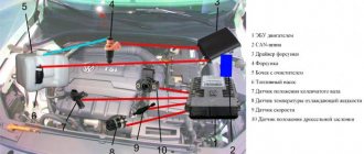
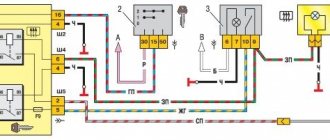
VAZ-21124 engine control circuit
Connection diagram of the VAZ-21124 engine control system with distributed fuel injection to Euro-2 emission standards (controller M7.9.7): 1 - ignition coils; 2 — nozzles; 3 - controller; 4 - main relay; 5 - fuse connected to the main relay; 6 — cooling system electric fan relay; 7 - fuse connected to the cooling system electric fan relay; 8 - electric fuel pump relay; 9 - fuse connected to the electric fuel pump relay; 10 — mass flow and air temperature sensor; 11 — throttle position sensor; 12 — coolant temperature sensor; 13 — solenoid valve for purge of the adsorber; 14 — oxygen sensor; 15 — knock sensor; 16 — crankshaft position sensor; 17 — idle speed regulator; 18 — immobilizer control unit; 19 — immobilizer status indicator; 20 - phase sensor; 21 — vehicle speed sensor; 22 — electric fuel pump module with fuel level sensor; 23 — oil pressure warning lamp sensor; 24 — coolant temperature indicator sensor; A - block connected to the wiring harness of the ABS cabin group; B — diagnostic block; B - block connected to the air conditioner wiring harness; G - to the “+” terminal of the battery; D — to the side door wiring harness block; E - block connected to the instrument panel wiring harness; G1, G2 - grounding points; I - the order of conditional numbering of plugs in the block of the immobilizer control unit; II - the order of conditional numbering of contacts in the diagnostic block.
Instructions for performing diagnostics
To diagnose a VAZ, a computer or diagnostic equipment is connected using a diagnostic connector.
Computer diagnostic socket
All broadcast codes are read by the scanner. They are stored in the controller’s memory until its power is turned off. Using special software, specialists decipher the codes and determine what malfunctions and failures exist in the system.
The diagnostic procedure consists of several stages:
- Suspension diagnostics. This procedure is performed if uneven tire wear, knocking or humming is detected when driving at a constant speed, making sharp turns, or on an uneven road. And also in case of premature activation of the ABC, increased free play of the steering wheel.
- Engine check. The power engine should be diagnosed if it runs intermittently, takes a long time to heat up, is difficult to start, as well as with increased fuel consumption, loss of power, the appearance of extraneous noise, or a decrease or increase in idle speed. During diagnostics, the electrical supply and ignition system are checked, and the pressure in the cylinders is measured (the author of the video is Pavel Master).
An automatic transmission is diagnosed in the following cases:
- no gear is engaged;
- When changing gears, noises, jerking, and slipping appear;
- increased fuel consumption;
- Oil leak detected.
During diagnostics, the scanner reads error codes of the automatic transmission control system, evaluates the readings of the throttle position and cooling system temperature sensors, as well as the position of the automatic transmission selector.
First of all, diagnostics are performed using a scanner. The scanner readings are deciphered and conclusions are drawn about problems in the system. At the second stage, analog testing is carried out - wiring, contacts, and batteries are checked. Next, an online check is carried out. The screen displays indicators of sensors, fuel injection, etc. Then the data obtained during posting is analyzed. At the last stage, the error codes stored in the controller’s memory are erased. After this, reinitialization is necessary.
VAZ-2112 harness diagrams
Instrument panel harness diagram
1, 2, 3, 4 – instrument panel harness pads to the front harness; 5 — block of the instrument panel harness to the side door harness; 6, 7, 8 — instrument panel harness pads to the rear harness; 9 – rear window heating switch; 10 – light signaling switch; 11 – windshield wiper switch; 12 – block of the instrument panel harness to the radio; 13 – mounting block; 14 — instrument cluster; 15 – heater control controller; 16 – heater motor switch; 17 — block of the instrument panel harness to the ignition system harness; 18, 19 — blocks of the instrument panel harness to the air supply box harness; 20 — ignition switch; 21 – fog lamp relay; 22 – sound signal relay; 23 — power window relay; 24 — starter relay; 25 – seat heating relay; 26 – external lighting switch; 27 – fog lamp switch; 28 – cigarette lighter; 29 – lampshade lighting of the glove box; 30 – glove box lighting switch; 31 – switch for rear fog lights; 32 – right steering column switch; 33 – socket for connecting a portable lamp; 34 — instrument lighting switch; 35 – brake signal switch; 36 – sound signal switch; 37 – alarm switch; 38 – air distribution drive gearmotor; 39 – VAZ-2112 illuminator; 40 — instrument panel harness block to the front harness; 41 – trunk lock drive switch; 42 – rear fog light relay.
A – grounding point of the instrument panel harness.
Source