The topic of this article is the VAZ-2110 engine (8 valves) injector in the fuel injection system. The main task is to find all its advantages and disadvantages and compare it with a carburetor engine. But to do this, you will need to delve a little deeper into history, look at how this engine was developed, how good it is in operation and repair. And the story will begin in the late 70s of the last century, when VAZ engineers started thinking about designing front-wheel drive cars. And then we will look at the injection system, its differences from the carburetor, its advantages and disadvantages.
Engine history
And now the story about where the VAZ-2110 engine (8 valves) injector comes from. And it was put in place at the end of the 70s. During these years, designers begin to understand that the classics produced for many years have a high cost. In addition, the Fiat 124 was the best car in Europe in 1964. Almost two decades have passed, the model range needs to be updated. And the experiments began. First of all, we modernized the gas distribution drive and started using a belt. But it did not take root on the VAZ-2105 engine (production years: 1980-1988), although it reduced the noise level.
The reason is simple: the pistons need scrapings that prevent them from hitting the valves if they break. But when repairing engines, pistons with 1.3 liter engines were installed, as a rule, of suitable size, but without recesses. But in the early 80s the eighth generation was released. Newer, comparable to European counterparts. And most importantly, the cars have front-wheel drive, a motor with a belt drive to a timing mechanism. And this was the same engine that, with a lot of modifications, is installed on modern cars. On models 2109 and 2110, these power units were adapted for the first time to an injection system.
Add a comment Cancel reply
You must be logged in to post a comment.
The VAZ 2110 is an injector engine that is distinguished by its efficiency, increased power and stability of operation when compared with the VAZ 2110 carburetor engines. The widespread use of injection engines at AvtoVAZ began in the 2000s. Today we will tell you in detail how the “tens” injection engine works.
It is worth recalling that injection engines on the “ten” were installed with different volumes and number of valves. Today on the secondary market you can find injection VAZ 2110 with 8 and 16-valve power units with a displacement of both 1.5 and 1.6 liters.
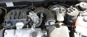
Main engine components
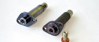
No significant differences may be detected upon a cursory examination. Both carburetor and injection systems do not affect the basic design of the engine. But it's worth taking a closer look at the little things. For example, take a look at the VAZ-2110 injector thermostat (8 valves). What immediately catches your eye is that it can be taken apart! Exactly! Engineers in Europe sit and think about how to reduce the life of a car, while ours at the same time carry out real improvements that are for the benefit of the consumer. It is clear that it is not the housing that breaks in the thermostat, but the insides - the temperature-sensitive element or valve. Therefore, why produce millions of cases? It will be much more profitable to make one for the car, and if the thermostat breaks down, change only the insides.
But these are not all the advantages of domestic engines. Please note that in the USA and Europe all cars are the same, sometimes there is no point in repairing it, it’s easier to throw it away and buy a new one. The reason is partly in the engine. For example, AvtoVAZ is almost the only plant that continues to install internal combustion engine blocks made of cast iron on its products! In all developed countries, aluminum alloys have long been used for this purpose! The service life of the engines suffers, but most importantly, there is no way to repair it, since it cannot be bored or relined. And this is much cheaper than buying a new engine or car. Maybe a wealthy burgher can afford this, but in our country a car is still a luxury for many people.
What is an injector?
Now let’s see what the injector circuit looks like on a VAZ-2110 car, let’s look at the main components and operating principle. But first you need to answer the questions of what an injector is and what it is needed for. Everyone knows that until the end of the 90s carburetors were installed. In them, with the help of air flows, mixture formation took place, and then supply to the intake manifold of the fuel system. Moreover, such a cunning device can mix gasoline with air in an ideal proportion - 14 to 1. But there is a game of vacuum and atmospheric pressure.
Replacing the fuel filter for VAZ 2110 2111 2112 engines
Details Parent category: Car repair VAZ 2110 2111 2112
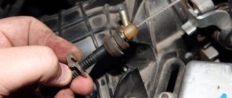
Replacing the fine fuel filter is regulated - every 30,000 km. However, its condition depends on the quality of the gasoline: the dirtier the gasoline, the faster the filter becomes clogged. Jerks when the car moves, first at high and then at low speeds, most likely indicate a clogged filter. There are currently two types of filters with two ways to attach them. The connection can be made by means of - a threaded connection (as for the example below) - by means of locking wire earrings (the earrings are pulled out, after which it becomes possible to disconnect the fuel hoses and install a new filter. After connecting the hoses, they are installed in place)
Injector features
But the VAZ-2110 engine (8 valves) injector is much simpler than the carburetor version. But this is from the point of view of an electrician. The fact is that the system consists of many electronic devices that are responsible for the operation of the entire engine. Instead of a carburetor, a ramp is installed on the intake manifold. Essentially, this is a piece of pipe that contains the air-fuel mixture. It is pumped from the tank using an electric pump under low pressure. By default, the ramp is completely sealed; it is separated from the intake manifold channels by electromagnetic valves - injectors. But here’s the peculiarity: a constant pressure is maintained in the ramp, which is regulated by a sensor, and the quality of the mixture and the amount of gasoline supplied depend directly on how open the throttle valve is.
Engine
Engine Specifications
| Model | 21083–80 | 2110 | 2111 | 2112 |
| Type | Four-stroke petrol | |||
| Number and arrangement of cylinders | Four, in-line | |||
| Cylinder diameter and piston stroke, mm | 82x71 | |||
| Working volume, l | 1,5 | |||
| Compression ratio | 9,9 | 9,9 | 9,9 | 10,5 |
| Rated power at crankshaft speed 5600 [4800]** min–1 according to GOST 14846–81 (net), kW (hp) | 50,8 (69,0) | 53,0 (72,0) | 56,0 (76,0) | 68,8 (93,5) |
| Maximum torque according to GOST 14846–81 (net), N m (kgf m) | 94,8 (9,66) | 103,9 (10,4) | 115,7 (11,6) | 128,3 (12,8) |
| Crankshaft rotation speed at maximum torque, min–1 | 3400 | 3400–3600 | 2800–3000 | 3700–3900 |
| Cylinder operating order | 1–3–4–2 | |||
**Different data for the 2111-16 engine are given in square brackets. Longitudinal section of the engine mod. 2110 Cross section of engine mod. 2110 Cross section of engine mod. 2111 Longitudinal section of engine mod. 2112 Cross section of engine mod. 2112 On cars of the VAZ-2110 family, engines of models 2110 are installed (Figure Longitudinal section of the engine mod. 2110 and Figure Cross section of the engine mod. 2110), 2111 (Figure Cross section of the engine mod. 2111) and 2112 (Figure Longitudinal section of the engine mod. 2112 and Figure Cross section of engine mod. 2112), created on the basis of engine mod.
2108Engines mod. 2108All engines are gasoline, four-stroke, four-cylinder, in-line. Engines mod. 2110 – carburetor engines mod. 2111 and 2112 - with a fuel injection system. The cylinder block is cast from special high-strength cast iron, which gives the engine structure rigidity and strength.
The coolant ducts that form the cooling jacket are made along the entire height of the block, this improves the cooling of the pistons and reduces the deformation of the block from uneven overheating. The cooling jacket is open at the top towards the block head. At the bottom of the cylinder block there are five crankshaft main bearing supports, the caps of which are secured with bolts. The supports are equipped with thin-walled steel-aluminum liners that act as crankshaft bearings. The middle support has grooves into which thrust half-rings are inserted, holding the crankshaft from axial movements. The crankshaft is cast from special high-strength cast iron. The main and connecting rod journals of the shaft are ground. To lubricate the connecting rod bearings, oil valves are drilled in the crankshaft and closed with plugs. To reduce vibrations, eight counterweights located on the crankshaft are used.
Mounted at the front end of the crankshaft is an oil pump, a timing belt pulley, and an alternator or damper drive pulley. A flywheel cast from cast iron is installed at the rear end of the crankshaft. A steel toothed rim is pressed onto the flywheel.
Forged steel connecting rods with covers on the lower heads. Thin-walled liners are installed in the lower head of the connecting rod, and a steel-bronze bushing is pressed into the upper head.
The pistons are cast from aluminum alloy. Each of them has three rings installed: the top two are compression rings and the bottom one is oil scraper. On the piston heads of mod. 2110 and 2111 have a recess for the combustion chamber and two recesses for the valves, for the engine mod. 2112 the piston bottom is flat with four recesses for the valves. On the engine mod. 2112 pistons are cooled with oil; for this purpose, special nozzles are installed in the main bearing supports. Injectors are tubes containing spring-loaded balls. While the engine is running, the balls open holes in the tubes and a stream of oil hits the piston from below.
The oil sump is steel, stamped, attached to the cylinder block from below with bolts.
A cylinder head cast from aluminum alloy is installed on top of the cylinder block. At the bottom of the head, channels are cast through which liquid circulates, cooling the combustion chambers. A camshaft is installed in the upper part of the head (engines mod. 2112 have two camshafts: one for the intake valves, the second for the exhaust valves). Engines have mod. 2110 and 2111, the camshaft rotates in supports, in the upper part of the cylinder head and two bearing housings secured with nuts on studs screwed into the cylinder head. The engine has mod. 2112 camshafts are installed in supports made in the upper part of the cylinder head, and one common bearing housing bolted to the cylinder head. The camshafts are cast from cast iron. To reduce wear, the working surfaces of the cams, the surfaces under the oil seal and the eccentric of the fuel pump drive are heat treated - bleached. The camshaft cams operate the valves through tappets. Engines 2110 and 2111 have steel adjusting washers installed in the upper part of the pushers; by selecting these washers, the clearances in the valve drive are adjusted. The engine has mod. 2112 hydraulic valve pushers are installed, which automatically compensate for gaps in the valve drive. Therefore, these engines do not need to adjust the clearances during operation.
Engines mod. 2110 and 2111 have two valves per cylinder: one intake and one exhaust, for the engine mod. 2112 four valves - two intake and two exhaust.
The guide bushings and valve seats are pressed into the block head. The guide bushings also have locking rings that keep them from falling out. Oil scraper caps are installed on the guide bushings to reduce oil penetration into the cylinders.
Engines have mod. 2110 and 2111, two springs are installed on each valve; the engine mod. 2112 – one. The camshafts are driven by a rubber toothed belt from the crankshaft.
Combined lubrication system: splash and pressure. Main and connecting rod bearings and camshaft bearings are lubricated under pressure. The system consists of an oil sump, gear oil pump with oil receiver, full flow oil filter, oil pressure sensor and oil valves.
The engine cooling system consists of a cooling jacket, a radiator with an electric fan, a centrifugal water pump, a thermostat and hoses.
The power supply system consists of an air filter, a fuel tank, a fuel pump, fuel lines and a carburetor for the engine mod. 2110 or a fuel rail with injectors and a fuel pressure regulator for engines mod. 2111 and 2112. In addition, the engine power supply system mod. 2111 and 2112 include sensors, fuel filter and throttle body. The fuel pump of the 2110 engine is mounted on the cylinder head and is driven by an eccentric on the camshaft through a pusher. Engines have mod. 2111 and 2112 electric fuel pump, submersible type, installed in the fuel tank and combined with a fuel level indicator sensor.
Engine ignition system mod. 2110 is a contactless type with an ignition distributor mounted on the cylinder head and driven and driven by the camshaft.
Engine ignition system mod. 2111 and 2112 microprocessor-based, controlled by a controller (control unit). The controller also controls the fuel injection system.
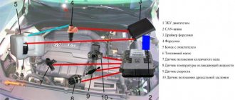
Diagram of the injection system
So, now in more detail about the power supply systems of the VAZ-2110 injection engine. First on the list is the fuel pump. It is mounted directly in the tank, together with the filter, and the engine rotor is driven only when the ignition is turned on (provided that the pressure in the ramp is below the minimum level). Next, the fuel flows through the tubes into the ramp. This is where the mixture is formed. The air first passes through a filter for purification. The filter housing is connected to the throttle assembly by a flexible pipe.
Repair of VAZ 2110-11-12 engine power supply system
Engine power supply system VAZ-2110. 2111, 2112
· Replacing the air filter · Replacing the engine fuel filter · Checking the engine injectors · Checking the pressure in the engine fuel system · VAZ-2111, -2112 engine power supply system · Removing the adsorber · Removing the idle speed regulator · Removing the fuel pressure regulator of the VAZ-2111 engine · Removing the housing air filter · Removing the throttle drive · Removing the engine injectors · Removing the fuel tank · Removing the fuel rail and fuel pressure regulator of the VAZ-2112 engine · Removing the fuel rail of the VAZ-2111 engine · Removing the electric fuel pump with a fuel level sensor · Removing the throttle assembly
Sensor system
The VAZ-2110 engine (8 valves) is no less interesting. The injector, a control system device, to be more precise, includes many sensors. All control occurs using sensors. So, between the filter and the throttle there is a mass air flow sensor. A position sensor is mounted on the damper itself. In the ramp - pressure. In addition, between the second and third cylinders on the surface of the internal combustion engine block there is a knock sensor. And on the generator drive pulley - engine speed. The vehicle's speed is measured from the gearbox. All data that comes from reading devices is sent to the electronic control unit.
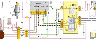
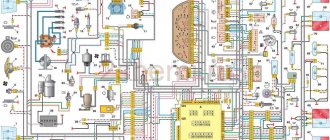
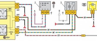
Diagram of VAZ 2110 injector 16 valves
1 – headlight unit 35 – instrument lighting switch 2 – front brake pad wear sensors 36 – ignition switch 3 – reverse light switch 37 – mounting block 4 – engine cooling system fan electric motor 38 – recirculation valve switch 5 – sound signal 39 – controller heater 6 – right front door locking motor 40 – hazard warning switch 7 – power window relay 41 – heater control lever illumination lamp 8 – 8 A fuse 42 – glove compartment lighting lamp 9 – starter 43 – glove compartment lighting lamp switch 10 – battery 44 – cigarette lighter 11 – generator 45 – on-board control system display unit 12 – windshield washer motor 46 – ashtray lighting lamp 13 – washer fluid level sensor 47 – brake signal switch 14 – left front door locking motor 48 – locking motor left rear door 15 – power window switch of the left front door 49 – power window switch of the left rear door 16 – coolant level sensor 50 – power window motor of the left rear door 17 – windshield wiper motor 51 – socket for a portable lamp 18 – recirculation valve 52 – clock 19 – micromotor gearbox for heater flap drive 53 – gearmotor for electric window lift of the right rear door 20 – electric motor for heater 54 – power window switch for the right rear door 21 – trunk lock switch 55 – gearmotor for locking the right rear door 22 – power window switch for the right front door 56 – side turn signal 23 – electric window motor of the right front door 57 – parking brake warning lamp switch 24 – door lock system control unit 58 – driver’s seat belt sensor 25 – additional resistor for the heater motor 59 – directional lamp 26 – brake fluid level sensor 60 – interior lamp 27 – electric window motor of the left front door 61 – interior air temperature sensor 28 – exterior lighting switch 62 – switch in the front door pillar 29 – instrument cluster 63 – switch in the rear door pillar 30 – rear fog light switch 64 – external rear lamp 31 – control lamp fog light 65 – interior rear light 32 – rear window heating indicator lamp 66 – license plate lights 33 – rear window heating switch 67 – trunk light 34 – steering column switch A – blocks for connecting the rear window washer motor B – blocks for connecting the harness injection system C – to the warning light harness connector D – connector for connecting to the on-board computer E – to the headlight cleaner harness connector F – connector for connecting to the fuel level sensor in the electric fuel pump module G – to the rear window heating element H – connector for connecting an additional signal braking J – to the trunk lock motor
Useful: VAZ-2104 diagram
See the complete diagram in one file below (click to enlarge):
Electronic control unit
This is, so to speak, the very heart of the system. On the VAZ-2110, the injector circuit comes down to precisely this device. A small case with many pins, and inside is the most interesting thing - a microcontroller. It is he who regulates the entire operation of the engine. The internal memory contains a so-called fuel map. Using it, the controller determines how much air and gasoline must be supplied to the ramp so that the engine operates in normal mode and detonation does not occur. But the most important thing is how long it is necessary to apply an impulse to the fuel injectors so that they open and inject the mixture into the combustion chamber.
Which is better: carburetor or injector?
And now a little about which VAZ-2110 engine will be more reliable: an injector or a carburetor? But you need to look at this issue from different angles. For example, beginners will like the injector. Constant speed, there is no need to shut off the air supply in cold weather, and starting off is much easier. But there is another advantage - the car is more responsive at high speeds. Even at a speed of 120 km/h, when you press the gas pedal, the car quickly picks up speed. With carburetor engines this happens much more slowly. Therefore, overtaking in a car with an injector is safer. But when starting from a traffic light, the carburetor will easily “break” the injector. And the reason is higher torque at the bottom. And the cost of maintenance, of course, is higher for injection “tens”, since sometimes it is not easy to make an accurate diagnosis in the event of a breakdown.
ECU diagnostics
In modern times, many methods have become available for conducting self-diagnosis or diagnosing a power plant malfunction with your own hands. Without any problems, you can purchase various diagnostic equipment, and you don’t have to go to a car service center. So, you can connect to the ECU using a standard OBD II cable and a tablet, or purchase an ELM 327.
Also, some errors can be diagnosed using the instrument cluster. First you need to enable test mode:
- The ignition is turned off. Battery included.
- Press the “Reset” control button and, holding it pressed, turn on the ignition. All positions of the familiar areas (segments) should light up on the LCD – LCD control.
- Press any of the control buttons. The LCD should display the program version (Ver 1.0).
- Press any of the control buttons. The following error codes (if any) should be displayed on the positions of the first and second lines of the LCD.
- Press the “Reset” control button and hold it for no more than 3 seconds. (maybe a typo, I need more than 3c). Error codes should clear to zero.
- Press any of the control buttons. All positions of symbols (segments) should light up on the LCD – LCD control.
Error codes: 2-overvoltage of on-board network;
3-fuel level sensor error (if a break in the sensor circuit is detected within 20s);
4-error of the coolant temperature sensor (if an open circuit of the sensor is detected within 20s);
5-outside temperature sensor error (if there are no sensor readings within 20s, indication on the LCD is “-C”);