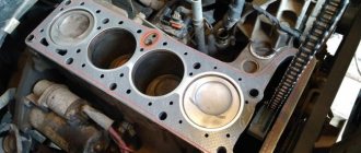
Niva 21213 sound signal does not work
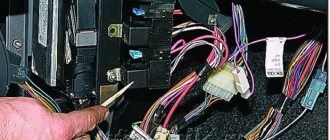
- Sound signal activation circuit
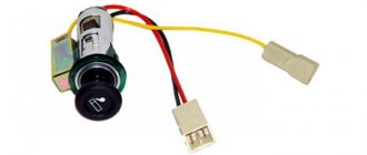
- 1 – plug socket for a portable lamp;
- 2 – sound signal;
- 3 – sound signal switch;
- 4 – fuse block.
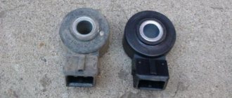
Sound signal Niva 2121 - type S-308 or S-309.
It is secured in the engine compartment on a bracket to the radiator frame panel. It is activated by the central button of the steering wheel. The contact ring of the switch is attached to the steering wheel, and the spring-loaded contacts are on the connector of the VAZ 2131 steering column switch. If the signal sound becomes weak and hoarse, adjust it by turning the screw on the housing in one direction or another. A non-functioning horn on a car is a very dangerous malfunction. The most unpleasant thing is that they find out about this breakdown just when the signal is needed most - in a dangerous situation on the road. What could cause the signal to fail?
There are several reasons why the horn may stop working. Almost all of them are electrical and simply involve no contact where it should be. Let's go through them all:
Horn fuse blown
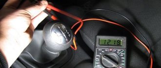
The very first and easiest check that can be performed when the sound signal is not working is the integrity of the fuse. If it turns out to be burnt out, then there may be a short circuit in the car. Try inserting a whole fuse that matches the rating (How to choose a fuse. Colors and ratings). If it burns out in the same way, it means there is actually a short circuit. If not, then perhaps the fuse has simply exhausted its resource and you should pay attention to other reasons.
The horn button does not work
The signal in most cars is turned on by a button in the center of the steering wheel. There are variations with a button in the steering column switch or a certain position of this switch itself, but this is rare.
There are actually a whole bunch of places inside the steering wheel where contact can be lost, leading to the failure of the horn. To understand exactly where they can be located, you need to understand how the sound signal in the car turns on. Let's look at the diagram.
Diagram for connecting an audio signal via a relay
This circuit assumes the presence of a signal activation relay. This relay is found on all modern cars. On a certain category of cars (for example, VAZ classics), there is no relay. In this case, the signal is connected directly through the button on the steering wheel.
The diagram shows that there are two electrical circuits: control and power. The power circuit feeds the signal and does not come into the car interior; the control circuit, on the contrary, comes to the steering wheel. When you press the signal button, the control contacts of the relay close, connect the power circuit and the signal turns on. What are relays, control and power contacts, read the article: how a relay works in a car .
The control current from the relay is transmitted from the steering column to the steering wheel through a floating contact. There may be one, or maybe two. These contacts rub against a special conductive ring built into the steering wheel at the point where it is attached to the steering shaft. Due to the fact that the contacts are spring-loaded, they are constantly pressed against the ring, ensuring the transmission of current to the steering wheel in any position.
Then the voltage is transmitted through a short wire to the button and when it is pressed, the electrical circuit closes to ground - the signal turns on. Now about malfunctions that can occur in the steering wheel.
ATTENTION!
It is better to entrust all work related to disassembling the steering wheel on cars with airbags to a car service center. Unskilled actions can cause the airbag to deploy, which can lead to life-threatening injuries!
— Worn contacts
The pressure contacts on the steering column rub against the slip ring whenever you move the steering wheel and wear out over time. Sooner or later, a moment may come when they can no longer reach the contact ring on the steering wheel and then pressing the horn button will lead to nothing. To avoid this, when removing the steering wheel for any repairs, it is necessary to lubricate the contacts and the ring on the steering wheel with a conductive lubricant, for example, graphite. Such treatment will reduce the friction of the contacts on the ring and extend their service life.
— Worn slip ring
Exactly the same malfunction can befall the conductive ring in the steering wheel. It can also wear out and lead to signal failure. The method of struggle is the same - lubricant.
Chevrolet Niva Metallica 4X4 › Logbook › Loud Fa-Fa or GAZ-24 horns
Ever since I bought the car, I was embarrassed to press the horn. It looks like a big beautiful car, and the sound of the horn is like that of an Oka. Finally, this was fixed. There aren’t many photos; there wasn’t much time to take pictures.
Two horns from GAZ-24 were purchased. High tone and low tone. Other materials needed: wire 2 sq.mm, wire 1 sq.mm, fuse 15A, waterproof fuse block with wires 2 sq.mm, large non-insulated automotive terminals, terminal ring, split automotive corrugation, 4-pin automotive relay , relay socket.
Actually, the wiring was assembled according to this diagram (yes, I don’t know how to draw in paint): Before installation, do not forget to remove the ground from the battery (or better yet, the plus too, because you will need to connect a wire to it, and do it directly on the battery is not convenient)
Well, a few comments on the diagram: Because. standard beeps consume 2.5 times less current (in the field there are two standard beeps of 3A each, that is, 6A, while the Volgov ones are each 7A and only 14A), Volgov ones cannot be connected to the standard wiring, the wires can overheat or even get burned due to this. Therefore, we draw a power line from the battery, installing a 15A fuse in the immediate vicinity. We use 2 sq. mm of wire (optimal for a load of 14A). To connect the beeps from the standard wiring, we need a relay. We connect the contacts of the relay winding (86 and 85) to the connector of the standard horn (we simply cut off the connector, and the wires through the relay block (I took a block without wires, and separately the terminals into it). We connect the positive wire to contacts 87 and 30, they will close when when the relay winding is triggered. There is no need to pull a ground to the Volga horns, since the pin with which they are attached is a ground contact (and all the hardware in the car has a mass). We connect the horns to each other with a 1 sq. mm wire (since for the second beep you need not 14A, but 7A), but you can use 2 sq. mm, it won’t be worse. We carry ALL the wires in a corrugated cable!
But then everything becomes much more interesting.
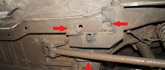
Because in a Shniva with air conditioning and ABS there is no space under the hood to install horns, you will have to remove the bumper like this:
We look at our undressed Shniva. The place in front of the radiators where one of the standard horns is located is also missing! But we have a bumper booster, there’s not even a lot of space under it, there’s just a lot of space! A little low, of course, but what can you do? We'll put it there. We take a drill, a metal drill and drill holes along the edges for the pin. I’ll explain why along the edges: if the horn suddenly gets covered, then you won’t have to remove the bumper, but remove the standard fender liner and gain access to the horn. We attach the horns to the drilled holes (don’t forget remove the second original horn, which is located under the fender liner on the driver's side. Together with the Volga horns, it will spoil the sound picture with its squeaking).
This is what a stripped Shniva looks like with two beeps installed:
Next, in order not to lengthen the factory wiring from the horn, and to secure the relay under the hood in an easily accessible place (I attached it to a ground stud next to the battery), you need to unravel it from the corrugation. But to get full access to this corrugation, remove the left (driver's side) headlight:
And we pull the wire out of the corrugation to the required length. We hide this wire in a new corrugation and lead it to where the relay will be.
Next, we assemble according to the diagram above.
We install the headlight, assemble the bumper, throw on the terminals and hum happily!
There were a lot of letters. Thanks to everyone who read!
Source
The signal does not work on the Niva Chevrolet | Auto-assistance
NIVA. The signal is not working. Possible malfunctions.
This is what helps prevent an accident.
Home Textbooks - Transport Niva Chevrolet release Design, operation, maintenance, repair. the signal is located between...
Thanks to the compressor, the air accumulates inside and has a reserve of a certain power when you press the button. The purchased signal for Chevrolet Niva replaces the standard one.
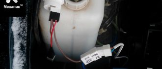
I extended the standard wiring through a two-wire block and secured it with plastic ties. And if it turns out that fuse F7 is intact, then the next step is to check the horn relay.
This system has a special design. Thanks to the compressor, the air accumulates inside and has a reserve of a certain power when you press the button.
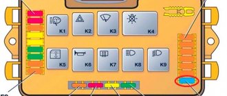
Additional relay and fuse box
It is located behind the glove compartment at the feet of the front passenger. To access, unfortunately, you will have to remove the glove box. The fuses for the electric fans of the cooling system and the engine control relay (injection system) are located here.
Scheme
Purpose
- Additional relay (turns on the right electric fan through an additional resistor at low rotation speed);
- Fuse (50A) protecting the power circuits of the additional relay and the right electric fan relay;
- Fuse for the fuel pump (fuel pump) (15A), protecting the power circuits of the electric fuel pump relay;
- Fuse (15A) protecting the constant power supply circuit of the controller;
- Right electric fan relay;
- Left electric fan relay;
- Electric fuel pump relay;
- Main relay;
- Fuse (50A) protecting the left electric fan circuits;
- Fuse (15A) protecting power circuits switched on by the main relay;
- Controller
Tips for motorists
The whole process took 40 minutes. I was much more confused about where to put the second signal. I installed it in front of the air filter, on its mounting bracket, one pipe on top, the other on the bottom.
Just two holes to drill!
Next, you need to assemble everything as before, but before that, don’t forget to check the signal’s operation. To be honest, I was very worried. What if the signal doesn’t work or the wiring doesn’t hold up for some reason.
But thank God there were no troubles, the signal went off, and I almost went deaf. I put the bumper back in place, tried the signal again - everything is still in order.
Replacing the standard Chevrolet Niva signal with a two-tone one
Lada 4×4 3D YMB 1.5 16V Turbo › Logbook › Air/Pneumatic signal
I honestly never understood this, and I won’t be able to understand, because the signal is only applicable in critical situations, and often only to warn someone... But as practice shows, the frequency of the “signal” exceeds any other sound present in the expanses of the road surface...)
If you often like to blow, and in response you want to blow so much that the ill-wisher would go to hell, congratulations, friends. This topic is for you.
This is Typhon T-9, the length of which reaches 57! centimeters, and the weight is 20 kilograms, the most powerful option not counting the ship's typhons for installation on a car:
To blow for a long time, or to blow at all, you need a fairly powerful compressor, and a receiver with a volume of at least 30 liters - in principle, standard. In practice, the regular Berkut R-20 can handle it too. The price tag also ranges from $100 minimum. Yes, it’s worth considering - the thing is quite scarce.
Next on the list is the Typhon T-37, less powerful, but more practical, mainly used by fans of loud pipes. The length is about 35 centimeters, the weight, compared to its predecessor, is symbolic - 4 kilograms. The price tag is also half and a half times less, and is generally $40 per unit in good condition.
S40V is the quietest signal of the above, which was installed on KraZ, ZIL, MAZ, etc., etc., and is acceptable for use on public roads. It doesn’t sound promising, but it can be used for your health :))
Well, as for Niva, as always, I didn’t find any easy ways, I threw away the thoughts of buying ready-made kit kits and started assembling my unique kit)
The first thing we purchased was a VIAIR receiver, but there is also a budget option from a military KamAZ, with a volume of 30 liters, the total volume of all three is 90, but it didn’t work for us due to the lack of any additional/auxiliary systems powered by compressed air.
Catalog number - 53205-3513014
The next thing was to purchase a compressor, in fact, an integral part of the operation of the air signal, oddly enough :)) My choice fell on the ARB CKMA12. Yes, 9000 hryvnia. — The most expensive component required.
Next, we just have to buy all the fittings for the receiver and pipe, the bypass electric valve, optionally make a bracket for mounting the compressor on top of the receiver, and actually choose the pipe. Here my choice fell on *drumroll*
Of course, I advise you to install this entire system further from your ears, because in case of punctures, you understand how loud the whistle will be;)) Passed))
Source