Schematic electrical diagrams, connecting devices and pinouts of connectors
Detailed color diagrams of the VAZ 2114 wiring (carburetor, injector) are provided with a description of the electrical equipment for various modifications. The information is intended for self-repair of cars. Many electrical circuits are divided into several sections for ease of viewing via a computer or smartphone; there are also circuits in the form of one picture with a description of the elements - for printing on a printer.
The VAZ 2114 (Samara-2) car is built on the VAZ 21093 platform and is an improved version of it. The first prototype of the hatchback was assembled back in 2000. A year later, the Volzhsky Automobile Plant produced the first pilot batch of 50 VAZ-2114 cars, and in the same 2001 the hatchback was first introduced to the market. The interior features a new instrument panel, a new steering wheel, an adjustable steering column, power windows and a new heater. Years of production 2114: 2001—2013
The fourteenth model was previously equipped with a 1.5 liter eight-valve engine, borrowed from the VAZ 2111 model with an injector. A little later it was replaced by the VAZ 11183-1000 version, which complies with the Euro-3 standard. The VAZ 2114 injector received a more powerful engine, and this is one of the reasons that the wiring of the 2114 has also changed.
A wiring harness has been added for connecting to the electronic switch. A harness has also appeared for connecting to the ignition module terminal.
Replacing high-voltage wires will require additional attention, because the connection procedure depends on the year of manufacture of the car. Until 2004, 4-pin ignition modules were installed, and after that - 3-pin. Connecting the adsorber valve to the injection system controller also provided another additional element. An adsorber is an electromechanical device used for ventilation and removal of condensate in a gas tank. Complications also affected the interior part. The dashboard received improvements in the form of the appearance of a BC (on-board computer), a new instrument panel and a change in the position of the glove compartment.
Car modifications 2114
VAZ-21140 . Modification with an 8-valve injection engine VAZ-2111, 1.5 liters and 77 horsepower. Serial production from 2003 to 2007
VAZ-21144 . Modification with an 8-valve VAZ-21114 engine, 1.6 liters and 81.6 horsepower. Years of serial production: 2007-2013.
VAZ-211440 . Another modification released in 2007, it was equipped with a VAZ-11183 engine with a volume of 1.6 liters and a power of 82 horsepower. The car was discontinued in 2013.
VAZ-211440-24 . Released in 2009, a modification with an injection 16-valve VAZ-21124 engine with a volume of 1.6 liters and a power of 89.1 horsepower. Discontinued in 2013.
VAZ-211440-26 . Modification with a 16-valve injection engine VAZ-21126, which complies with the Euro-3 environmental standard, with a volume of 1.6 liters and a power of 98 hp. The car was produced from 2010 to 2013.
Historical reference
The four-door VAZ 2110 sedan was produced by the Volzhsky Automobile Plant from 1995 to 2007. And unlike the usual Lada cars, the model was positioned as a higher-class car.
VAZ 2110 on the factory conveyor
In particular, the car was equipped with:
- electronic engine control system (ECM);
- diagnostic unit (on-board computer);
- galvanized metal was actively used in body parts;
- the body was painted using a new, more progressive technology.
Wiring diagram VAZ-2114 for old models
Electrical diagram of car 2114: 1 - headlight; 2 [Installed on a part of the car] - fog lamp; 3 — ambient air temperature sensor; 4 — electric engine radiator fan; 5 — block for connection to the wiring harness of the engine control system; 6 — engine compartment lamp switch; 7 [Installed on a part of the car] - reserve block for connecting an audio signal with one terminal (the negative terminal is connected to the body); 8 — sound signal; 9 — liquid level sensor in the windshield washer reservoir; 10 [Installed on a part of the car] - brake pad wear sensor; 11 — low oil level sensor; 12 - generator; 13 [Installed on a part of the car] - engine compartment lamp; 14 — temperature indicator sensor; 15 — starter; 16 — battery; 17 [Installed on a part of the car] - relay for turning on fog lights; 18 — coolant level sensor in the expansion tank; 19 — sensor of insufficient brake fluid level; 20 — reversing light switch; 21 — windshield wiper gear motor; 22 — emergency oil pressure sensor; 23 — rear window washer electric pump; 24 — electric pump for windshield washer; 25 — instrument panel; 26 — mounting block of fuses and relays; 27 — brake signal switch; 28 — ignition relay; 29 - ignition switch (lock); 30 — glove box lighting lamp; 31 — switch for the glove compartment lighting lamp; 32 — rear window heating switch; 33 — rear fog light switch; 34 [Installed on a part of the car] - fog light switch; 35 - combined switch for side lights and headlights; 36 — alarm switch; 37 — steering column switches; 38 — brightness control for instrument lighting; 39 — illumination lamp for the headlight hydraulic adjustment control handle; 40 — socket for connecting a portable lamp; 41 — side direction indicator; 42 — interior lighting switch (front door open sensor); 43 — interior lamp; 44 — electric fan of the ventilation and heating system; 45 — additional resistor of the electric fan of the ventilation and heating system; 46 — switch for operating modes of the electric fan of the ventilation and heating system; 47 — illumination lamp for the handle of the operating mode switch of the electric fan of the ventilation and heating system; 48 — backlight lamp for the heater control unit; 49 — display unit of the on-board control system; 50 [Installed on part of the car] - trip computer; 51 — interior lighting switch (rear door open sensor); 52 [Installed on a part of the car] - block for connecting a clock; 53 — fuel module; 54 — ashtray illumination lamp; 55 — cigarette lighter; 56 — interior lamp; 57 — switch for the parking brake warning lamp; 58 — rear light; 59 — license plate light; 60 — additional brake light; 61 — heating element for heating the rear window; 62 — rear window wiper gear motor; A - numbers of pins in connecting blocks.
VAZ-2114 diagram (second option)
Electrical diagram of VAZ-2114 cars (without engine control system):
1 — block headlights; 2 — fog lights; 3 — air temperature sensor; 4 — electric motor of the engine cooling system fan; 5 — blocks connected to the wiring harness of the ignition system; 6 — engine compartment lamp switch; 7 — block for connecting to a single-wire type audio signal; 8 — sound signal; 9 — washer fluid level sensor; 10 — front brake pad wear sensor; 11 — oil level sensor; 12 - generator; 13 — engine compartment lamp; 14 — coolant temperature indicator sensor; 15 — starter; 16 - battery; 17 — relay for turning on fog lights; 18 — coolant level sensor; 19 — brake fluid level sensor; 20 — reverse light switch; 21 — windshield wiper gearmotor; 22 — oil pressure warning lamp sensor; 23 — block for connecting to the rear window washer electric motor; 24 — electric motor for windshield washer; 25 — instrument cluster; 26 — mounting block 2114; 27 — brake light switch; 28 — ignition relay; 29 — ignition switch; 30 — glove box lighting lamp; 31 — glove box lighting switch; 32 — rear window heating element switch; 33 — rear fog light switch; 34 — fog lamp switch; 35 — switch for external lighting lamps; 36 — alarm switch; 37 — steering column switches; 38 — switch for instrument lighting lamps; 39 — lamp for illuminating the headlight hydrocorrector scale; 40 — plug socket for a portable lamp; 41 — side direction indicators; 42 — lamp switch on the front door pillars; 43 — lamp for individual interior lighting; 44 — heater fan electric motor; 45 — additional resistor of the heater electric motor; 46 — heater fan switch; 47 — heater switch illumination lamp; 48 — lamp for illuminating the heater levers; 49 — on-board control system unit; 50 — trip computer; 51 — lamp switch on the rear door pillars; 52 — block for connecting the wiring harness of the engine control system; 53 — electric fuel pump and gasoline quantity sensor; 54 — front ashtray illumination lamp; 55 — cigarette lighter 2114; 56 — trunk lighting lamp; 57 — trunk light switch; 58 — interior lamp; 59 — parking brake warning lamp switch; 60 — rear external lights; 61 — rear internal lights; 62 — block for connection to the rear window heating element; 63 — license plate lights; 64 - additional brake signal located in the spoiler.
Conventional numbering of plugs in blocks:
- A — headlight blocks;
- B — electric fuel pump block;
- C — blocks of the mounting block, ignition switch, windshield wiper gearmotor;
- D — blocks for the interior lamp.
Wiring diagram VAZ-2114 new models
The updated engine has a new injection scheme, so it was necessary to use some new devices, as well as replace the ignition coil with a more efficient one and adapted to Euro 3 conditions. In order to comply with them, the engine had to minimize the amount of CO at start-up. And for this it was necessary to lean the mixture. Since a lean mixture ignites worse, it needed a more powerful spark to spark. This explains the use of a coil of increased power.
- block headlights;
- gearmotors for headlight cleaners*;
- fog lights*;
- ambient temperature sensor;
- sound signals;
- engine compartment light switch;
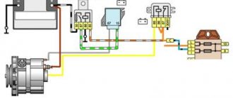
- engine cooling fan electric motor;
- generator VAZ-2114;
- low oil level indicator sensor;
- washer fluid level sensor;
- front brake pad wear sensor;
- wire ends connected to the common windshield washer pump**;
- windshield washer pump;
- headlight washer pump*;
- wire ends for connecting to the rear window washer pump on VAZ-2113 and VAZ-2114 cars;
- low oil pressure indicator sensor;
- engine compartment lamp;
- wire lug for connecting to the engine management system wiring harness;
- windshield wiper gear motor;
- starter VAZ-2114;
- block connected to the wiring harness of the ignition system on carburetor cars;
- coolant temperature indicator sensor;
- reverse light switch;
- low brake fluid level indicator sensor;
- accumulator battery;
- low coolant level indicator sensor;
- relay for turning on fog lights;
- mounting block;
- brake light switch;
- plug socket for a portable lamp;
- hydrocorrector scale illumination lamp;
- parking brake indicator lamp switch;
- block for connecting a backlight lamp;
- switch for instrument lighting lamps;
- Understeering's shifter;
- hazard switch;
- front seat heating element relay;
- ignition switch;
- rear fog lamp circuit fuse;
- front seat heating elements circuit fuse;
- door lock circuit fuse;
- front ashtray illumination lamp;
- ignition relay;
- cigarette lighter VAZ-2114;
- glove box lighting lamp;
- glove compartment light switch;
- heater fan motor;
- additional heater motor resistor;
- heater fan switch;
- heater switch illumination lamp;
- heater lever illumination lamp;
- gear motors for electric windows of the front doors;
- right front door ESP switch (located in the right door);
- gear motors for locking front door locks;
- wires for connecting to the right front speaker;
- gear motors for locking rear doors;
- wires for connecting to the right rear speaker;
- door lock control unit;
- wires for connecting to radio equipment;
- headlight wiper switch*;
- rear window heating element switch;
- rear fog light relay;
- block for connection to the heating element of the right front seat;
- rear fog light switch;
- right front seat heating element switch;
- fog light switch*;
- switch for external lighting lamps;
- left front seat heating element switch;
- block for connection to the heating element of the left front seat;
- wires for connecting to the left front speaker;
- left front door power window switch (located in the left door);
- right front door power window switch (located in the left door);
- wires for connecting to the left rear speaker;
- side direction indicators;
- dome light switches on the front door pillars;
- dome light switches on the rear door pillars;
- lampshade VAZ 2114;
- individual interior lighting lamp;
- block for connecting to the wiring harness of the electric fuel pump;
- trunk light switch;
- instrument cluster;
- trunk light;
- on-board control system display unit;
- trip computer*;
- block for connecting the wiring harness of the engine management system;
- rear exterior lights;
- rear interior lights;
- pads for connecting to the rear window heating element;
- license plate lights;
- additional brake signal located on the spoiler.
Relays and fuses VAZ 2114
F1 for 10 Amps (A) rear fog lights and rear fog light warning lamp. F2 for 10 A turn signal lamps, turn signal relay, hazard lights, hazard warning lights. F3 7.5 A lamps for interior lighting (both) and trunk, ignition lighting, powertrain control system control lamp, brake lamps, computer, if available. F4 20 A carrier, relay and rear window heating element. F5 20 A horn and its relay, cooling fan. F6 30 A power windows and their relays F7 30 A motor heater, headlight cleaner, windshield washer, cigarette lighter, glove compartment light bulb, rear window heating relay winding. F8 7.5 A right fog lamp. F9 7.5 A left fog lamp. F10 at 7.5 A left side marker, lamp signaling the inclusion of the side light, lamps for illuminating the sign, engine compartment, illumination of switches and instruments, instrument lighting switch. F11 at 7.5 A right side. F12 at 7.5 A right low beam. F13 at 7.5 A left low beam. F14 for 7.5 A left high beam and a light indicating that the high beam headlights are on. F15 at 7.5 A right far. F16 30 A - a light indicating insufficient oil pressure, brake fluid level, engagement of the parking brake, low battery, instrument cluster, relay for monitoring the health of lamps, indication of control systems, reversing lamps, turn indicators and their relays, as well as an alarm if turning mode is turned on, computer, generator excitation winding is turned on at the moment the engine starts.
How to check the fuse?
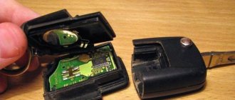
Next you need to find the faulty one. There are two ways (depending on the type of fuse).
We either simply take it out and see if the middle part is intact (in the photo - burnt out on the left, serviceable on the right).
The second method is more accurate. The fact is that the human eye may not notice a burnt jumper.
We do the following: Turn on the non-working circuit (for example, dimensions), without removing the fuse, look at the voltage at one end of the fuse, then at the other. If there is voltage at one end, but not at the other end, then the fuse has blown.
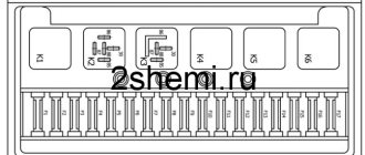
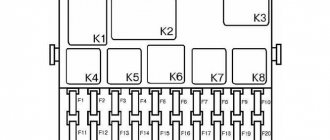
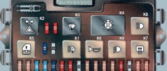
Location of relays and fuses (new)
K1 - relay for turning on headlight cleaners; K2 - relay-interrupter for direction indicators and hazard warning lights; K3 - windshield wiper relay; K4 - lamp health monitoring relay; K5 - power window relay; K6 - relay for turning on sound signals; K7 — relay for turning on the heated rear window; K8 - headlight high beam relay; K9 - relay for low beam headlights; F1-F20 - fuses.
Relay for turning on rear fog lights, installed on cars of the VAZ-2108, VAZ-2109 and VAZ-2110 families.
Other markings - 22.3777
,
2302.3777
.
PTF service
At the same time, many owners of the first ten cars do not know where the fog lamp fuse is located. And if it malfunctions, they don’t know how to replace it.
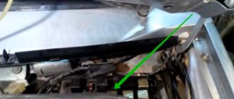
To get to the PTF fuse, you need to remove the mounting block from the instrument panel niche with your own hands
On models after 2000. fuses are grouped in a single block.
Their technical parameters are as follows:
- The rear PTF fuse is marked F20 and is designed for a current of 7.5A;
- Fuse F4 at 10A is responsible for protecting the front right fog lamp;
- Fuse F 14 at 10A is responsible for protecting the front left fog lamp.
Side of VAZ fuses of the tenth family
The algorithm for the operation of fog lights has also been changed.
- The headlights are turned on by pressing a button that supplies power to a relay type 113.3747 installed in the mounting block;
- Turning on the PTF on VAZ 2110 cars is only possible if the headlight switch is set to the exterior lighting position.
In other words, PTFs are activated only with side lights or low beam headlights. At the same time, the activation is indicated to the driver using a light indicator on the button and on the instrument panel.
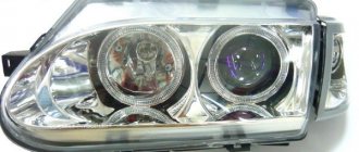
There are no particular problems with replacing lamps in the headlights, since they were installed in an open position for service. But with the rear lamps we had to struggle a little, since the entire structure of the headlight unit was located in the trunk lid.
To replace a burnt-out lamp, you must remove the entire unit
Content
Principle of operation
The relay is designed to turn on and off the rear fog lights of the vehicle in accordance with the algorithm according to UNECE Regulation 048:
- The rear fog lights are turned on by pressing the locking button once without locking, connected between contacts 3 (“Common”) and 5 (“On/Off”) when there is supply voltage on contacts 2 (“Fog lights”) and/or 6 (“ Low beam/high beam") of connector X1 (i.e. if the low or high beam headlights and/or fog lights are on).
- The rear fog lights are turned off by pressing the same button once or when the supply voltage is removed from contacts 2 and 6, and if the voltage is reapplied to contacts 2 and/or 6, the rear fog lights do not turn on.
Replacement is easy
Having figured out where the block that controls the operation of the PTF power circuit is located, replacing it is a trifle. It is much more difficult to correctly diagnose a breakdown. Therefore, if for some reason there is no power to the rear fog lights, you should start by checking the fuse and cleaning the contacts.
For the latter, you can use regular fine-grit sandpaper. This must be done extremely carefully, because the relay block contains electromagnets, with the help of which the contacts are switched (when the light button is pressed).
If there is no power supply to the VAZ rear lights, and the fog lights do not work together with it, then this does not indicate a breakdown of the relay, but a damage to the electrical circuit or a short circuit in the system (most often, the absence of a negative contact from ground).
To accurately determine the cause, it is advisable to use a multimeter. If only the rear lights do not light up, this indicates:
- damaged fuse;
- absence of 1, 2, 6 contacts (voltage on them);
- switch closure (momentary button);
- problem with electrical wiring (break).
As practice shows, the relay on the PTF VAZ 2114 fails extremely rarely. Most often, only a break in the contacting area or mass contact occurs due to body vibrations. A faulty relay should be the last thing to blame.
What are fog lamps for?
The main task of the PTF is to illuminate the space in front of the car. Correctly adjusted “fog lights” can illuminate a section of road 10–15 meters long. This distance is quite enough for safe movement by car in poor visibility conditions. The switching on and off of such lighting devices must be fully controlled by the driver.
Adjustment of fog lights is carried out during their installation. The procedure does not take much time, but requires care and precision. You can install the rear and front PTFs yourself.
Fog lamp relay VAZ 2110: differences in factory configuration
Like any modern car, the VAZ “ten” was constantly improved during the process of mass production. However, all modifications concerned the originally installed components and assemblies of the vehicle. For example, front fog lights were not included in the external lighting of the car, but both a relay and a PTF control button were installed in the electrical circuit.
The VAZ 2110 rear fog lamp relay has been installed since 2000
For reference: in the rear block headlights, the side light lamp had a second filament, which served as fog lights. It was activated by a button on the front panel and made it possible to improve the visibility of the car in conditions of poor visibility for other road users driving behind.
How can you install PTF on a VAZ 2113, 2114, 2115
Installation of fog lights on a car can be done in different ways. The car owner chooses a specific option based on his own capabilities, preferences and wishes. There are three main ways to install PTF:
- Purchasing a bumper with pre-installed fog lights. Similar parts are presented in a wide variety at tuning studios, where they can be purchased and installed immediately. Adjustment and connection are carried out by service specialists. The disadvantage of this method is that the cost of the work is too high.
One way to install foglights is to buy a bumper with already built-in PTFs
Front bumper VAZ 2115 with holes for fog lights
Purchase and subsequent installation of a set of “fog lights” from the PTF kit
Installation diagram of fog lights
The connection of fog lights is carried out according to certain rules. They, first of all, relate to the placement of PTF on the car. The locations for installing headlights are strictly defined.
Layout of daytime running lights
Manufacturers of modern car models pre-mark the PTF installation locations on the bumpers. As a rule, such lighting elements are most often available in the luxury version of the car. If the headlights themselves are missing, then their installation sites are closed with special plugs.
Distance at which fog lights can be placed
How to install a PTF: necessary materials and tools
Installation of fog lights, regardless of the chosen installation method, requires the presence of certain parts and tools, without which it is impossible.
What are the button and relay for?
A special button and relay are a must - “fog lights” are very powerful equipment for car electrical wiring. The absence of such parts can provoke high current loads on the terminals and the ignition switch, which will cause burnout of contacts, damage and overheating of the insulation protection and short circuit with failure of the electrical network.
In order to install fog lights on a VAZ, you need to assemble certain parts in advance or purchase a ready-made kit. The cost of such a set rarely exceeds one thousand rubles.
The PTF kit includes:
- wires with blocks and terminals for a specific VAZ model. There are three of them as standard: one connects the headlights, the second goes to the relay from the switch, and the third goes from the relay to the fuse box;
Set of wires with terminals and blocks for installing PTF
Fog lamp relay for VAZ 2113, 2114, 2115
Button to turn on PTF on Lada
Plastic ties and clips that secure wires
PTF for VAZ 2115
Which PTFs should you prefer? The headlights themselves are chosen by the driver to his taste, but the main thing when choosing is not to make a mistake with the power, so as not to overload the generator and the car’s electrical wiring. It is better not to purchase headlights with xenon: the generator has a certain power reserve, but is not designed for too high loads. Regular light bulbs will be sufficient.
Signs of problems with the PTF relay
The main reason why it may be necessary to replace the fog lamp relay is the malfunction of the latter. But don’t rush to conclusions and rush to buy a new relay. By itself, it is a fairly reliable design, and in combination with a small number of consumers and low current in the circuit, this device rarely fails.
Therefore, before replacing the PTF relay, you should check other elements in the fog lamp circuit, namely:
- light bulbs;
- wiring;
- power button;
- circuit breakers.
The latter should be given special attention, since two fuses are responsible for protecting the fog lights, designated in the general block as F8 and F9. In some cases, they may be serviceable, but due to oxidation of the contacts they will not pass electric current. In this situation, they should be carefully removed and their contact surfaces, as well as the contact surfaces of the sockets in the common block, should be cleaned. Very often, after this procedure, the headlights begin to work.
A sure sign that the fog light relay is working properly, and the cause of the problem should be sought in the wiring or fuses, is a situation when only one of the headlights does not light up. Checking and, especially, replacing the relay in this case is pointless.
If, after checking, all the links in the fog light chain are in good condition, but the headlights themselves still refuse to turn on, you should proceed to checking and, probably, replacing their relays.
How to connect fog lights with your own hands
Before directly installing the headlights, their location is determined. In the case of the VAZ 2115 car, the bumper already has standard holes for installing additional lighting fixtures. Similar ones can be cut in the bumpers of VAZ 2113 and VAZ 2114.
There is no need to spoil the appearance of the bumper - fog lights are easily installed on special brackets. Many PTF kits contain special decorative plugs that add attractiveness and neatness to the installed headlights and facilitate the installation process.
Installation and connection algorithm
- Installation of a power button in the car interior. In the case of the VAZ-2114, the place for the button is on the left side of the driver on the front panel. However, its placement can be arbitrary - the main thing is that it is convenient for the driver to drive the car. Often, PTF power buttons are installed instead of plugs on the control panel.
A PTF activation button is installed in the cabin in a place convenient for the driver.
The power button is connected, chips are connected to it
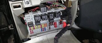
Under the hood there is a block to which the PTF relay will be connected
The wiring harness connects to the fuse box
The PTF relay is located in the engine compartment
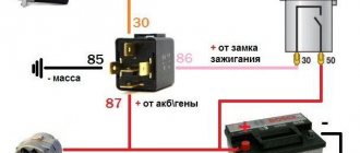
PTF connection diagram
Wiring diagram for connectors and terminals of fog lights
The functionality of the entire connection can be checked by turning on the side lights - only then will the fog lights work.
Fog lights only function when the side lights are on
After completing the installation of the PTFs on the car, they only need to be adjusted correctly. The flow of light should not blind drivers in the oncoming lane.
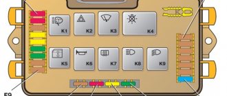
Old style mounting block
Older car models have a different type of mounting block. The fuse for VAZ 2114 fog lights is also installed separately for each headlight. In the old-style block, the element responsible for the right fog is designated F 9 , and for the left one - F 8 .
The maximum permissible load for each element is 7.5 amperes.
F9 and F8 are located first and second from left to right in the bottom row.
Useful : Fog lights don't light up (7 reasons)