The modern Lada Granta model is in demand among domestic car enthusiasts due to its optimal cost and sufficient reliability. Good strength and low cost of consumables further stimulate demand among the population. The downside of the car is frequent breakdowns in the electrical part. On-board systems often fail. The website contains a detailed electrical diagram of Grant with explanations and interpretation.
Full pinout of Grant, divided into several sections for a more detailed image and easier perception. Present here.
- The engine compartment - the harness combines all the elements of the wires located in the area of the engine and main instruments.
- Salon module. The design is further divided into zones that provide for the connection of individual parts of the wiring.
- Instrument panel module. All elements coming from sensors, instruments and indicators are concentrated here.
- The rear harness is located in the rear of the car and is responsible for supplying power to the lighting, lock and instrument modules.
All the given transcripts are taken from the manufacturer’s official instructions and fully comply with the factory designations and the standard version diagram.
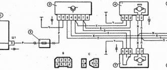
Grant's electrical circuit responsible for the engine compartment
Here are the main parts of the Lada Granta wiring, which are responsible for the normal operation of the power plant:
- 1 – power supply to the headlight, front right;
- 2 – power supply for windshield washers;
- 3 – voltage to the left side of the head optics;
- 5 – on-board power supply;
- 6 – head fuse block;
- 7 – generator;
- 8 – horn;
- 9-11 – terminal blocks to the dashboard;
- 12 – contact pair of rear headlights;
- 13 – main radiator fan drive.
How to turn off an alarm if it won't turn off
With emergency shutdown function. To remove the lock, you must enable service mode. Also, every owner of a car with an alarm system should be aware of where the Valet button is installed in the car. It is usually installed in the cabin, near the fuse box. With this button you can interact with the alarm control unit - add additional security functions, reflash key fobs, etc.
And if a situation occurs when the siren screams and does not turn off, then using this button you can enter the access code that was originally registered during installation of the alarm. For a clear example, in order to turn off the howling of the siren, you will need to turn on the ignition, then press the Valet button 2 times and then turn off the ignition. After these steps, the alarm will turn off and you can start the engine and drive away.
Method 2 is the most effective and will most likely turn off the alarm. If you manage to get into the car, and the alarm is screaming at full blast, then you just need to press the “open” button on the key fob in a row. After some time, the system will respond to the key fob and the siren will turn off. And all because in most cases the connection between the alarm control unit and the key fob is simply lost. And if you constantly press Unlock, it will strengthen the radio transmission, after which contact will resume.
Every owner of a car equipped with a security alarm can experience an unpleasant situation when the key fob shows no signs of life and it is impossible to use it to disarm the car and turn off the alarm.
In this article we will talk about the possible causes of the breakdown and what actions need to be taken in this case.
Does the alarm not turn off? What to do?
Modern security devices with two-way communication allow you to inform the owner about the reason for the operation, displaying on the key fob or the owner’s phone screen which of the sensors was triggered (shock, volume, tilt or movement, an attempt to start the engine without a security tag, etc.). In the case of older devices, the LED acts as a source of response data, which, when the vehicle is disarmed, shows the sensor response zone using a certain combination of flashes. A decoding of these signals is attached to the operating instructions for the security complex.
Frequent alarms are a wake-up call for the owner and indicate possible malfunctions in its operation, caused by one reason or another, or by attempts to steal your car. In any case, in the event of continuous false alarms, you should contact specialists as soon as possible to carry out a full diagnosis of the alarm and eliminate the problem.
It is probably just necessary to adjust the sensitivity of the sensors and make additional settings, but more serious problems are possible.
Advice. In any case, do not completely disarm the car. If the alarm siren disturbs those around you, set the alarm to “quiet” mode, park the car in a guarded parking lot until you contact a specialized service - it is quite possible that the process of theft is already underway (we wrote in detail about methods of theft earlier)
Also, in case of problems with the alarm system, the following algorithm of actions should be performed:
Lada Granta diagram - ignition part
- 1 – indicator of lubricant pressure in the crankcase of the power plant;
- 2 – generator connector;
- 3 – power supply to the fuel mixture supply valve;
- 4 – cooling system thermometer;
- 5 – sending a signal to the dashboard;
- 6 – adsorber purge;
- 7 – speedometer;
- 8 – mass air flow sensor;
- 9 – DPKV;
- 10 – DC in front of the catalyst;
- 11 – control pulse device;
- 12 – oxygen concentration sensor in exhaust gases;
- 13/14 – coil and spark plugs, respectively;
- 15 – injector drivers;
- 16 – ignition contact group;
- 17 – detonation measurement sensor.
Grant instrument pinout - dashboard diagram
This part is the most difficult. The large number of pins and the miniature size of the terminals greatly complicates the search for the required group:
- 1/2 – connecting blocks for the front electrical harness;
- 3/4 – similar for the feed harness;
- 5 – lighting control unit;
- 6 – ignition switch module;
- 7 – on-board computer;
- 8 – lever for switching the position of the wipers;
- 9 – tidy;
- 10 – control of emergency modes;
- 11 – cargo compartment lid lock;
- 12 – diagnostic connector;
- 13 – block for the air intake drive;
- 14 – button to turn off the heated rear windshield;
- 15 – emergency contact;
- 16 – brake light switch;
- 17/18 – contact group – output to radio equipment (radio tape recorder);
- 19 – rotating equipment module;
- 20/41 – driver/passenger airbag drive;
- 21 – horn power supply;
- 22 – mounting block group;
- 24 – cigarette lighter group;
- 25 – backlight for stove control;
- 26 – interior lamp;
- 27 – contact group of the ignition switch;
- 28 – controller;
- 29 – incoming connector to the rear of the on-board network;
- 30 – electronic part of the gas pedal;
- 31 – additional resistor;
- 32 – stove motor;
- 33 – heater switch block;
- 34 – door lock module;
- 35/36 – cooling system head fan relay;
- 37 – compressor relay wiring;
- 38 – additional relay or reverse indication coil;
- 39 – air conditioner switch button;
- 40 – automatic transmission drive;
- 42 – evaporator thermometer;
- 43 – output to the rear wiring harness.
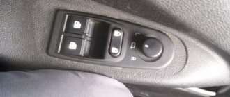
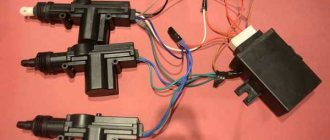
What is required to install central locking on 2 doors?
- A working and installed car alarm system with power outputs for controlling door locks.
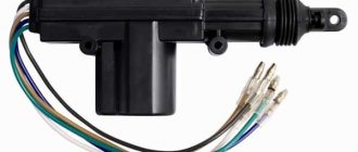
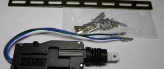
- Activators, actuators, actuators, solenoids, electric drives or, finally, just central locks - 2 pcs.
- The wires are two-core, copper. The diameter or cross-section of each wire must be at least 0.75 square. Length about 3-4 meters.
- Plastic clamps - 10 pieces, maybe more, “in reserve.”
- Other: electrical tape, heat shrink tubing, wire cutters, screwdriver, soldering iron, solder, multimeter, drill, drill bits, electrical extension cord, etc.
Before we begin directly installing central locks, we will analyze each point above in order, in more detail.
1) In this article we will not talk about how to install an alarm yourself, but we will assume that it is already installed. The cheapest option (about 1,300 rubles) is a simple alarm without feedback.
Which model to choose, how to connect correctly, how much it costs and other questions about car alarms will be discussed in another article. Just a few important points to keep in mind.
Firstly, the main alarm unit must have a connector (usually 6-pin) with power outputs for connecting door locks. Secondly, before purchasing, decide in advance whether you need an additional alarm channel. It can be used to open the trunk or, for example, implement the “light path” function and other similar functions. It all depends on your imagination and ideas, so it’s up to you. 2)
Lock activators are not called by any name, so don’t be surprised by so many names. We will stick to this term. The central locking solenoid most likely refers to an electromagnet, which is most often installed to open the trunk. In terms of power (traction force) it is much stronger than plastic activators, but it is also more expensive.
The approximate price for a regular central locking activator with 2 outputs (two-wire electric lock) is 100-120 rubles. a piece. For 2 doors you will need two activators, the total cost is about 250 rubles. The kit for each activator includes a special strip for attaching the central lock and self-tapping screws, as well as a rod, screws and a metal retaining plate.
3) To save insulating tape, copper wires in general insulation around the insulated conductors, but you can also buy them separately (single-core). The cross-section of the conductor must be at least 0.75 square. The current consumption of a conventional electric central locking drive can reach 5A at its peak.
In auto stores you can choose wires of various diameters, colors and lengths. Some are sold in ready-made installation kits or kits. Individually or “by meter,” most often, single (single) wires are found.
We recommend going to a regular electrical supply store and purchasing a two-conductor copper cable (the individual wire of which has a stranded conductor). For example, a PVS 2×0.75 cable (with a polyvinyl chloride sheath) or a PVS 2×1 mm cable is suitable. These wires are used to connect various electrical appliances, power tools and other machines and devices. The cost is about 12-15 rubles per 1 meter.
You can look for special automotive PGVA wires, which are intended for automotive equipment and instruments. They also have polyvinyl chloride insulation and are undoubtedly suitable for connecting central locks.
For reference: PGVA wires are designed for flexible connection of electrical equipment and devices with a low rated voltage (up to 48 V) in temperate, tropical and cold climates. PGVA wire is resistant to vibration loads, cracking, gasoline and oils. When laid alone, it does not spread fire.
When installing additional devices and using a second alarm channel, carefully study the table with permissible current loads. Most likely, to install a powerful solenoid that will open the trunk lock, an additional unloading relay will be required.
Plastic tape clamps will be needed to secure the wires. Purchase at will, 10 pieces will be enough.
A set of 100 pieces measuring 2.5×100 costs about 50 rubles.
5) Other tools, devices and materials that may be needed during installation.
Grant ECU pinout
The Lada Granta uses two types of electronic engine control units. Fundamentally, the systems differ slightly, which excludes the possibility of their interchangeability.
| Contact | 11183-1411020-51/52 | 11186-1411020-21/22 |
| A1 | DPKV | |
| A2 | Not involved | |
| A3 | Entering the first knock sensor | |
| A4 | Not used | |
| IN 1 | DPKV | |
| AT 2 | Not involved | |
| AT 3 | Input of the second knock sensor | |
| AT 4 | Main relay output | Not used |
| C1 | Empty | |
| C2 | DTV | |
| C3 | Mass air flow sensor | |
| C4 | UDC | |
| D1 | DDC weight | |
| D2 | Empty | |
| D3 | DTOZH | |
| D4 | Not applicable | |
| E1 | Zeroing the TPS | |
| E2 | Empty | CAN L |
| E3 | Empty | CAN H |
| E4 | Canister purge valve output | |
| F1 | Body from DTV | |
| F2 | Speedometer input | |
| F3 | Not applicable | DFM |
| F4/G4/H4/J4 | Output from injector No. 1/2/3/4 | |
| G1 | Antifreeze temperature sensor ground | |
| G2/G3 | Not used | |
| H1 | On-board electronics grounding | |
| H2 | UDC | |
| H3 | Not involved | Battery charge indicator output |
| J1 | Terminal No. 15 from the ignition switch | empty |
| J2 | Entrance No. 2 TPS | |
| J3 | DDC | |
| K1 | Supplying voltage to the TPS | |
| K2 | Entrance No. 1 TPS | |
| K3 | UDC | |
| K4 | DDK heater power connector | |
| L1/M1 | Leads to the ignition coil ¼ and 2/3 cylinders respectively | |
| L2/M2; L3/M3 | Not involved | |
| L4/M4 | Throttle actuator pin 5/6 | |
Self-installation of central locking
The central lock can be safely classified as of secondary importance. You can do without it, but having it is much more convenient and safer. Due to the promotion of new car models, it is already accepted that the vehicle, when leaving the assembly line, is equipped with a central lock.
This device has a very convenient function. Thanks to it, the car owner can easily open and close all the doors of his vehicle at the same time. As for its design, we can say that it is a control unit connected to the actuators via wires. The process of controlling the lock is carried out using either a key fob or just a key.
Many car owners want to replace a conventional lock with an automated one, but due to the lack of extra financial resources, they always postpone this procedure until later. Indeed, if you ask a car repair shop to install a central locking system, you will be shocked by the amount that will be quoted only for the work done by specialists. Therefore, in order to ensure that the family budget does not go into the red, we will describe how you can install a lock yourself.
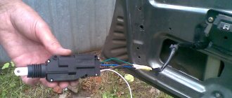
The first thing to do is remove the door trim. It follows from this that it is necessary to purchase a set of latches (plastic), with which the casing is attached. The clips are disposable, so you can’t do without them. It is definitely worth disconnecting the terminals from the battery, because this work involves working with electrical wiring, and this, as we know, is not very safe.
So, the casing along with the dust curtain has been removed. Next, you need to decide on the place where the actuator will be installed. When choosing a location, it is necessary to take into account the movement of the glass with the window lift mechanism. Analyze everything so that you don’t have to repeat this procedure later. Quite often, car owners have to resort to making a special bracket, with which the lock itself will be attached.
You have already determined the location where the central lock will be located, so you can safely begin installing it. In order for it to function efficiently, it must be paired with the rod of the original lock, which is responsible for the process of raising and lowering the button responsible for closing the door. In order for the traction to be good, it is allowed to bend it. The movement of all parts should be very soft. If there are interferences, you should reconsider everything again.
Next, let's look at the wiring. It is necessary to pull the wires through the corrugated pipe. This pipe is located in the intermediate section, located between the body pillar and the door. It protects the wires from possible chafing of the wires during vehicle operation. Next, you should study in detail the instructions supplied with the lock and connect the required wire to the alarm unit.
We can say that almost everything has been accomplished. In fact, doing this work is much easier than you could imagine. After all that has been done, it is necessary to check the operation of all electrical and mechanical parts of the central locking system. Before you begin, you need to connect the necessary wires to the battery. Once you are completely confident in the correct operation of the lock, you can assemble all the previously removed components of your vehicle, that is, secure the trim with rivets.
Thanks to the installation of a new central lock, you will not only be more convenient, but also much easier and more comfortable. It should be remembered that there are types of locks that are equipped with an option that automatically closes the door after a few seconds. Although, this is quite convenient, since sometimes in a hurry the driver may forget to close the door. But it is problematic if the keys are left in the car by mistake. There may also be a lock that closes the door after the motor has been brought into operation.
At this stage, both the work and your familiarization with existing types of central alarm systems are completed.
Progress does not stand still; new technical solutions and developments appear every day. In the world of automotive electronics, there are already a lot of instruments and devices that can make life easier for the driver. One of such devices is the central lock. And in this article we will talk about how to independently install the central lock on classic VAZ models.
Grant relay diagram
Relay location in the main mounting block located in the engine compartment:
- 1 – drive of the cooler of the cooling system;
- 2 – central locking protection;
- 3 – secondary starter relay;
- 4 – additional part of the relay;
- 5 – turn signal and emergency signal breaker relay;
- 6 – wiper drive protection;
- 7/9 – insertion of high/low headlight modes;
- 8 – horn protection element;
- 10 – heated aft windshield;
- 11 – main relay block;
- 12 – fuel pump relay.
Detailed diagram of the VAZ Grant (dashboard)
The vehicle is supplied to the market with a 32-pin instrument panel as standard. The standard pinout of the Grant shield has only 26 pins involved. Residual connectors are provided for the possibility of adding equipment or custom modifications:
- 1 – to the low oil pressure sensor in the engine crankcase;
- 2 – to the handbrake indication switch;
- 3 – intended for service needs when diagnosing the instrument panel;
- 4 – to external lighting switches;
- 5/6 – similar for right and left turn signals, respectively;
- 7/8 – CAN L/H;
- 9 – indication of seat belt position;
- 10 – contact of the Reset button of the steering column lever;
- 11 – response of the brake fluid reservoir sensor;
- 12/13 – on the head optics, high/low beam position;
- 14/15 – foglight terminals front/rear, respectively;
- 16/18 – receiving immobilizer antenna signal;
- 17 – ground wire of the instrument panel;
- 19/21 – to terminal No. 30/15;
- 20 – for the drive of the electric power steering unit;
- 22 – for door closing sensors;
- 23/24 – MK buttons for forward and reverse, respectively;
- 25 – for an environmental thermometer;
- 26 – gas tank float indication.
Connecting the signaling to the central locking system
Now we get to the most interesting part. The contacts of the signaling relay must be connected to the gap in the brown wire (see diagram in Chapter 1). Moreover, this will be required regardless of the configuration. Oddly enough, we won’t need power cables at all. And the task now looks like this: you need a two-wire signal cable connected to the break in the brown cord.
The moral here is:
- If you were able to remove the central lock control unit, connect the cable to the break in the wire connected to pin “7” of the control unit;
- If you have removed the door trim, then pull the cable out of it (from the point where the brown cord breaks).
Lada Granta: wiring diagram for rear wiring harness devices
The rear part of the car wiring is responsible for the equipment of the stern and sides of the car. all additional equipment is connected exclusively through this part of the highways:
- 1/2 – contact group for the dashboard;
- 3/4 – direction indicators;
- 5 – handbrake indicator;
- 6 – rear window heating contact;
- 7 – interior lamp;
- 8 – indicator of the driver’s seat belt position;
- 9 – cargo compartment illumination lamp;
- 10 – fuel pump drive;
- 11/15 – aft dimensions for the left and right sides;
- 12 – trunk lid lock drive;
- 13 – button for turning on the interior lamp;
- 14 – additional stop chain;
- 16-19 – door terminal blocks for the rear left, rear right, front left and front right doors;
- 20 – airbag control drive;
- 21 – contact group of license plate lights;
- 22 – on the dashboard;
- 23/24 – rear speed indicator sensors;
- 25/26 – seat belt pretensioners;
- 27 – group of dashboard contacts.
The need for alarm and model selection
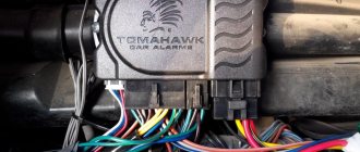
Today, the number of cars on the streets of megacities is increasing every day, and not everyone has personal garages. For this reason, most of the population leaves their cars in paid parking, but what to do if there is none close to home? In such a situation, the best solution would be to install a reliable security system that will allow you to leave the car overnight, ensuring its safety. It is advisable to install the Lada alarm system immediately after purchasing the car. This can be done at the nearest car service center for a fee, or you can connect the system yourself.
Before installation, you must select a suitable security system. Today the market offers a wide range of different alarm systems for vehicles. In most cases, they differ only in the set of functions. It should be borne in mind that cheaper devices will not be able to provide sufficient reliability.
Lock connection diagram
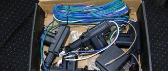
It is recommended to use the StarLine alarm system for a domestic car in the budget segment, as it is highly reliable and affordable. In addition, it is quite easy to install it yourself. When purchasing a device, you must additionally purchase the following equipment:
- 3 limit switches for doors (the system includes only 1 for the driver’s door);
- 3 connectors for limit switches;
- special wiring 11 m long;
- Alfa bell device for 12V.
All of the components listed are low in cost, so you won’t feel any extra costs. The security system is quite simple to install. The main thing is to understand where the alarm connection points go and connect all the wiring in a certain sequence.
Preventive measures
In order for the factory wiring of the Lada Grant to serve for a long time and not break, experienced experts strongly recommend following a number of simple rules.
- Periodically check all contact connectors and terminals for oxidation and rust. Such damage to the connections can cause a short circuit and a critical decrease in the conductivity of the line, which is perceived by the on-board computer as an error or breakdown.
- Use only original consumables and electronic components. The use of counterfeit products does not guarantee the functionality of the circuit. At the same time, some elements, when damaged, cause a voltage drop in the network, which becomes a direct cause of failure of other equipment or a fire.
- Use special oil to treat contact groups. The fluid is sold in auto shops or electronics stores. After treatment, the contacts are covered with a moisture-impermeable layer, which increases their service life by 2-3 times.
- Carefully monitor the charge level and condition of the battery. The wiring of the Lada Granta critically perceives a significant voltage drop in the on-board circuits. As a result, this may cause damage to the firmware of electronic control units.
Programming the duration of control pulses
Even if the alarm is connected correctly, it is not a fact that the owner will be able to control the locks from the key fob. The point is that it is necessary to correctly select the duration of the control pulse (for locking and for opening). There is no need to make it too large so as not to overheat the actuators.
See what exactly the manufacturer Starline offers. We can set the pulse duration to 0.7 s, which should be enough. The value “3.6” will be redundant at the same time.
The “Lux” package has the following property: after 15 minutes of inactivity, the electronics “fall asleep”. It may take an extra boost to wake her up. So, try to use the option that provides for a double pulse. The main thing is not to activate the “comfort” option, which uses a 30-second duration. To connect the signaling with “comfort”, you need to install an additional unit in Grants (AvtoVAZ does not produce it). We wish you success.