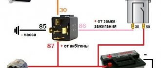
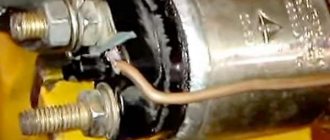
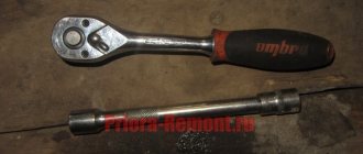
During the entire period of operation of the Priora, there were no such problems when I could not start the engine) But this could not last forever. And on one hot summer day, having turned off the engine at a gas station, I could no longer start it. The pump pumps, but the starter doesn’t turn, okay, it doesn’t turn, there’s not even a click. The first thing I thought was a problem with the battery terminal, but no, everything was in place. Frustrated, I pushed the car away from the pump, after which I began to think about what other problems there might be. The immobilizer immediately came to mind. Since the gas station was not so far from home, I decided to go get a training key. But returning to the car 30 minutes later, the engine started without him. Strange, I thought. But I was definitely pleased with the outcome. I was even more upset when the engine did not start again. The symptoms were the same. But after cooling down, the engine started. I immediately started thinking about the mass of the starter. I unscrewed it, cleaned it, screwed it on, no result. I decided to read the forums, most likely someone had already had the same problems. Immediately I found several references to this problem. Prior owners struggled with this by installing an additional relay on the starter. I decided to try this method too. It all started with a trip to the store. Where it was purchased: 1. 4-pin relay. 2. Female connectors and ring terminals. 3. Wires. I spent a little more than 100 rubles on this. Installation is not difficult, here is the diagram.
After I installed all this, the car stopped acting up in this way.
CONCLUSION: If the starter turns perfectly when it’s cold, but stops when it’s hot, then I advise you to start by installing an additional relay.
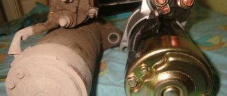
Disassembling the starter
We disassemble the starter 2110-3708010-02 to replace the traction relay, brush holder with brushes and drive elements.
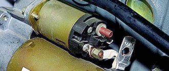
The traction relay can be replaced on the car. For clarity, we show the replacement of the traction relay with the starter removed. Using a 13mm socket, unscrew the nut of the lower contact bolt of the traction relay and remove the wire tip from it.
Use a Phillips screwdriver to unscrew the two screws securing the traction relay...
...and remove it. We remove the spring and the traction relay armature from the front cover.
Using the “8” wrench, unscrew the two coupling bolts.
Separate the housing and the front cover.
We remove the armature with the brush holder and the back cover from the body.
Using a Phillips screwdriver, unscrew the two screws...
...and remove the back cover. A wavy spring washer is installed in the bearing seat of the rear cover.
Remove the insulated brushes from the brush holder.
Remove the cover of the planetary gearbox.
We take out the three satellites of the planetary drive gear.
Remove the rubber plug. By pressing your finger on the end of the drive shaft...
...remove the drive assembly from the front cover.
Use two screwdrivers to open the support eye and remove the drive lever. We support the end surface of the ring gear on a wooden block. By placing the jaws of the open-end wrench “at 13” on the limit ring of the drive gear travel...
...and hitting the key with a hammer, we press the restrictive ring.
Use a screwdriver to pry up the locking ring and remove it. Remove the limiting ring of the drive gear.
Remove the overrunning clutch with the drive gear assembly.
Using a screwdriver, move the retaining ring out of the shaft groove and remove it.
Remove the ring gear of the planetary gearbox from the drive shaft.
We insert two metal plates between the bearing and the armature commutator and rest them on the jaws of a vice, striking with a hammer, through a soft metal drift into the end of the shaft, and compress the bearing. By external inspection we check the condition of the commutator and armature windings. Charring of windings is not allowed. If the collector is slightly burned, we clean its plates with fine abrasive sandpaper. If the commutator is severely burned and worn, the armature should be replaced. We remove scuffing and envelopment of the sliding bearing material on the armature shaft journal using the finest sandpaper, followed by polishing. Using an ohmmeter, we check the short circuit of the armature winding to its core. The ends of the windings must be well soldered to the lamellas. Blackening of windings and separation of varnish insulation from them is not allowed. When the brushes wear out, replace the brush holder assembly. We assemble the starter in the reverse order. We install the brush holder before installing the armature in the stator. Before installing the brush holder on the armature commutator, remove the springs of all four brushes so that the brushes slide into the guides.
To do this, bend the four spring holder clamps...
...remove the spring. After installing the brush holder on the armature commutator, install the springs and bend the clamps of the spring holders. We install the back cover and attach the brush holder to it. We apply CV joint-4 lubricant to the gears of the planetary gearbox.
We install the limiting ring of the drive gear on the locking ring using sliding pliers.
When installing the housing on the anchor, use the handle of a hammer to hold the anchor from being attracted by the permanent magnets of the stator and lower the stator onto the back cover.
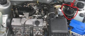
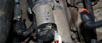
The car starter starts the engine. The Priora will not start without his participation. Without it, starting a movement is simply impossible. Sometimes the Lada Priora does not start because the fuse has blown, or the starter relay has malfunctioned; it is marked K3. Sometimes it clicks but doesn't turn. The reasons are in the details. The starter on a Priora consists of the following parts: bendex, retractor relay, armature and others - for a complete list of how many parts the starter of a Priora car contains, see the article below. It is advisable for car owners to know where this mechanism is located on a Lada Priora car - it is located immediately under the air filter. The price of the part is a starter for a Priora engine (16 valves): from 2750 to 4500 rubles. When a breakdown occurs, the device on the Priora stops turning.
There is nothing to be done - you will have to get it out and figure out the problem. Despite the rather “brute” force that the starter unit “applies” to start the engine, its structure is quite complex and consists of several fairly small parts. So, you will have to understand the relay mechanism in detail, because problems may also arise in it. Photo of the detail below.
Replacement
In order to replace the starter of a Priora car, prepare the 13th and 15th keys. Before removing the mechanism, be sure to remove the negative from the battery - this little procedure is very important this time. Next follow the instructions:
- Remove the air filter, then its housing.
- On the starter assembly, unscrew the nut that secures the terminal.
- Remove the terminal from the contact bolt.
- Disconnect the wire and terminal.
- Remove the starter assembly mounting nuts (there are 2 or 3 of them, depending on the type).
- Remove the starter assembly. Install the new one in reverse order.
Standard starter and analogues - article number and price
Lada Granta starter relay
Unfortunately, if the mechanism does not work, the problem can only be solved by replacing it. Neither installing new parts under the body, nor any cleaning will save the situation. The standard starter for a Priora with 16 valves goes under catalog number 2111.3708010-01, its cost is about 4,000 rubles. As analogues we can consider:
- "Baker." Article 5702370800010, costs 3,700 rubles;
- "Starvolt." Article lst0190, price - 3,200 rubles;
- Valeo. Article 438285, costs from 3,700 rubles;
- For automatic transmission, article number 219002370801000, costs from 3,900 rubles;
- "BATE". Article 51323708000, costs from 2,750 rubles;
- Gearbox – 51213708000bate, costs from 2950 rubles;
- "Kzate." Article 5702370800, costs from 3,300 rubles;
- Pramo (Eltra). Article TS12E901, price – 3,800 rubles;
- Fenox gearbox. Article 2110-3708010, price – 4,500 rubles.
Changing the cigarette lighter
Where is the starter relay on the VAZ-2114: photo and location + video
Most drivers do not use the cigarette lighter for its intended purpose, forgetting that many devices that use current are connected through the cigarette lighter. As a result, a common problem arises - the cigarette lighter does not work. The composition of the cigarette lighter on VAZ-2170 cars is the same as that of many other models - it is a metal spiral, which is covered with a plastic casing. A special connector is used to heat the coil. Repairing the cigarette lighter connector for minor faults is often carried out without dismantling.
The cigarette lighter fuse on a Priora can be removed quite easily. Like other Priora fuses, it simply snaps off. The usual fuse replacement scheme: identify the blown element, replace it with a new one with a specific installation location in the block. In this case, the current strength of the replacement part will depend on the location of the installation location.
It may be that replacing the fuse will not bring the expected result. Then, first of all, it is recommended to conduct a thorough check of the wire. The insulation coating on it may be damaged. You also need to check how tightly the connection terminals are inserted. It also happens that the wire that powers the device is disconnected.
Buying a cigarette lighter fuse for a Priora is not a problem today. Domestic stores offer a large selection of auto parts for various models
At the same time, it is important to take into account the advice of experts and buy factory-quality spare parts manufactured in Russia
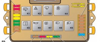
Relay and fuse blocks on a LADA Priora car
Where is the ignition relay located in a VAZ-2114 car?
The VAZ Priora passenger car, regardless of the type of engine installed, is equipped with several junction boxes. They are located under the hood and inside the car. The use of several boxes made it possible to separate circuits with high and low currents. In addition, separate small-sized mounting blocks were installed, introduced as the configuration expanded.
Main power fuse block
The vehicle's power circuits are protected by inserts installed on the positive terminal of the battery. The block is designed to protect circuits with maximum currents. To gain access to the fuses, you need to remove the plastic cover; this can be done without the help of tools.
Block diagram and its location in the car
The removal of the most powerful circuits on the Lada Priora into a separate unit located close to the battery ensured maximum protection of the car's electrical system from overloads.
The location and designation of the inserts is indicated in the photo. Depending on the year of manufacture and installed equipment, it is possible to install fuses of different ratings.
Priora power insert block
Explanation of fuse designations
Purpose and rating of the main block inserts.
The given fuse diagram for the Lada Priora is relevant for cars without an anti-lock brake system. The introduction of a hydroelectronic unit on the Priora-2 series car led to a change in the purpose of the inserts.
Purpose of fuses on the battery for Priora cars with ABS (starting from the one closest to the terminal):
- F1 - ECM protection (30 A);
- F2 - power steering (50 A);
- F3 - generator circuits (60 A);
- F4 - similar to F3;
- F5 - power supply to the ABS unit (40 A);
- F6 - similar to F5, but rated at 30 A.
Mounting block: relays and fuses in the passenger compartment
The unit includes fuses, several relays, and tweezers designed to simplify the procedure for replacing burnt out inserts. The content of the device depends on the vehicle configuration.
Block diagram and its location in the car
The unit is located in the plastic frame of the dashboard at the bottom of the driver's side. The outside of the box is closed with a removable cover installed around the steering column and secured with three locks located along the lower edge. To remove the cover, you need to turn the latches 90 degrees and remove the element from the latches by pulling it towards you.
The oval marks the location of the block installation
On cars, fuse ratings may differ depending on the year of manufacture of the car and the configuration. To determine the value of the fuse link, you should use the operating instructions for the Lada Priora.
When repairing fuses, it is necessary to take into account that the instructions for the Lada Priora car change several times a year. It is not recommended to use a manual from another car.
The “norm” option with the additional installation of an air conditioner has differences in the Priora’s fuse circuit. Elements that protect the device are placed in a separate engine compartment, discussed below. The mounting housing itself has not undergone any changes.
Block version “norm” with air conditioning
With the start of production of the modernized Priora-2, the contents of the body changed somewhat. In the interior units of cars, only one space for a relay and two cells for fuses are empty.
Block on Priora-2
Explanation of fuses and relays
Explanation of fuses in the “norm” version.
Questions and answers How to bleed shock absorbers before installation
Read more
Questions and answers How to adjust the carburetor on a trimmer
Read more
Questions and answers How to remove the window lifter handle on a Hyundai Accent
Read more
Questions and answers How to remove a dent on a car with your own hands
Read more
Questions and answers Which shock absorbers are better to install?
Read more
Questions and answers Which carburetor is better to put on a Ural motorcycle
Read more
Questions and answers What sandpaper should I use to matt a car before painting?
Read more
Questions and answers Car stalls at idle
Read more
Questions and answers When the engine is cold, it starts and immediately stalls
Read more
Great article 0
Stories from our readers
“Fucking basin. "
Hi all! My name is Mikhail, now I’ll tell you a story about how I managed to exchange my two-wheeler for a 2010 Camry. It all started with the fact that I began to be wildly irritated by the breakdowns of the two-wheeler, it seemed like nothing serious was broken, but damn it, there were so many little things that really started to irritate me. This is where the idea arose that it was time to change the car to a foreign car. The choice fell on the melting Camry of the tenth years.
Yes, I had matured morally, but financially I just couldn’t handle it. I’ll say right away that I am against loans and taking a car, especially not a new one, on credit is unreasonable. My salary is 24k a month, so collecting 600-700 thousand is almost impossible for me. I started looking for different ways to make money on the Internet. You can’t imagine how many scams there are, what I haven’t tried: sports betting, network marketing, and even the volcano casino, where I successfully lost about 10 thousand ((The only direction in which it seemed to me that I could make money was currency trading on the stock exchange, they call it Forex. But when I started delving into it, I realized that it was very difficult for me. I continued to dig further and came across binary options. The essence is the same as in Forex, but it’s much easier to understand. I started reading forums, studying trading strategies. I tried it on a demo account, then opened a real account. To be honest, I didn’t manage to start earning money right away, until I understood all the mechanics of options, I lost about 3,000 rubles, but as it turned out, it was a precious experience. Now I earn 5-7 thousand rubles a day. I managed to get the car buy after half a year, but in my opinion this is a good result, and it’s not about the car, my life has changed, I naturally quit my job, I have more free time for myself and my family. You’ll laugh, but I work directly on the phone)) If If you want to change your life like me, then here’s what I advise you to do right now: 1. Register on the site 2. Practice on a Demo account (it’s free). 3. As soon as you get something on the Demo account, top up your REAL ACCOUNT and go to REAL MONEY! I also advise you to download the application to your phone, it’s much more convenient to work from your phone. Download here.
- The controller controls the on/off of the additional starter relay depending on the crankshaft speed and the time the starter cranks the engine.
- After setting the ignition key to the “Starter” position and the crankshaft rotation speed not exceeding 500 min1, the controller sends a signal to an additional relay and thus turns on the starter.
- After being turned on, the starter will work until the ignition key is in the “Starter” position for no more than 20 seconds, provided that the “correct” password has been received from the immobilizer and the crankshaft speed has not increased to 500 min1. This prevents the starter from turning on when the engine is running and its overheating during prolonged cranking.
In other words, why do you need an additional starter relay :
- To protect the starter from accidental (due to wear, prolonged starting) sintering of contacts in the ignition switch;
- In order to turn off the power to the starter when the engine has started, but the key, for some reason, continues to be in the “starter” mode;
- Relieves the load on the ignition switch contacts.
How to check the additional starter relay , is it installed in the “ten”?
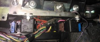
- First, check the presence of an additional starter relay in the mounting block. This relay is mounted and is indicated by an arrow in the photo.
- Secondly, you can check its operation as follows: turn the starter in the cylinder purging mode, after 12-13 seconds the starter should turn off automatically.
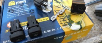
Installing an additional starter relay
By the way, stores have a kit of additional starter relays for self-installation.
For example, a kit from Avtoelektronika, which contains everything necessary for installation, however, the circuit included in the kit turned out to be unfinished. For the additional relay to operate correctly, it was necessary to add a 1A direct current diode to the circuit (1N4000-1N4007 or the Russian analogue KD243(A-Zh)). The absence of an additional starter relay does not mean that there is an urgent need for it. For example, many foreign cars do not install such a relay either. And car enthusiasts whose relay has failed do not see the difference after dismantling it, so it makes sense to devote time to other modifications to the car’s electrical system.
Source
Basic functions and operating principle of automotive fuses
Modern cars can no longer be imagined without the use of electronics. And electronics, like any equipment, can fail and, as a rule, at the most inopportune moment. To protect electrical circuits, a well-known element - a fuse - has long been used. The main task of any fuse is to protect the electrical circuit. Automotive fuses are no exception.
The Priora series of domestic cars uses fusible elements. If the current in the electrical circuit exceeds the permissible value, the fuse element burns out and opens the circuit. To make fusible elements, an alloy or one type of metal is used. The body in which the fusible elements are placed is made of a special type of glass. Typically, the housing is a system of fastenings, between which a fusible element is fixed. This arrangement of elements is typical for Lada Priora fuses.
The fuses in the Priora are located where the battery is, that is, under the hood. This placement is primarily related to safety. The marking of the elements is indicated by the Latin letter F, which indicates that they belong to devices with low power.
The marking of fuses and relays, their location in the Priora mounting blocks depends on the configuration. For example, F9 indicates the heater fan fuse, and F3 or F15 may indicate where the fuel pump fuses are located on a Priora.
The electrical circuit of the VAZ-2170, as well as other Prior modifications, is characterized by the use of three types of relays. The main relay block (or the first, main relay) is located on the left side of the driver. There is also a mounting block and an additional block, they are located near the passenger seat.
On Priors with air conditioning, a fuse and relay block is additionally built in to carry out monitoring functions for devices that regulate the state of the climate. In cars with light sensors, the low beam lamps are powered through a relay, which is usually designated K1 in the diagrams, but there may be other designations.
How to make a start button instead of an ignition key in a car with your own hands
In older cars, often the wires from the starter itself are connected directly to contacts inside the contact group, which close when the ignition key is turned. When the starter is activated, a very large amount of energy is consumed, which means a large current flows (the contacts strike a spark). Over time, a burnt deposit forms on the contacts or they completely burn out, no longer providing reliable contact. Newer vehicles have a separate relay that closes the starter contacts when the ignition key is turned.
The main advantages of using a relay in the starter power circuit:
- Such a system is more reliable, since the relay is designed for high currents and lives much longer. - The relay can always be replaced - The contact group behind the ignition key works for a very long time, since it turns on only the relay that takes the main load.
Regardless of whether your starter is turned on by a relay or directly by a contact group, all operations to connect the starter are still performed by turning the key.
First you need to determine which contacts are responsible for the start and connect them to the start button.
To do this, you need to disassemble the plastic protection under the steering wheel of your car. Very often, a connector with all the necessary wires is connected to the contact group of the key well at the back. There should be locking tabs on both sides of this connector. You need to press on them and pull out the connector.
Fuse power
All fuses are color coded depending on the power for which their fuse links are designed:
- The fuses for the cooling system fan (F1), heated rear window (F2), and the interior heater motor (F9) are designed for a current of 25 A;
- fusible elements of the high beam headlight fuses (F3, F4), sound signal (F5), hazard lights (F8), 15th terminal of ABS (F16), fog lights (F17, F18) protect circuits designed for a rated current of up to 10 A ;
- 7.5 A fuses protect the circuits of low beam lamps (F6, F7), instrument panel, interior lighting, brake lamps (all F10) and rear fog lamp (F21);
- side lights (F14, F15), immobilizer (F20) – 5 A fuses;
- wiper motor (F11) – 20 A fuse element;
- heated seats (F19) – protected by a 15 A fuse;
- the most powerful fuse is 30 A - protection of electrical circuits (F31 or F27).
Replacing fuses of a higher rating with a smaller one, as well as the reverse replacement, is not allowed. If a fuse protecting the light signal or active safety circuits of the vehicle blows, it is allowed to replace it with a similar one removed from the socket of the circuit responsible for comfort or others that do not affect the safety of the vehicle when it is moving. If possible, the protection of electronic circuits must be restored in accordance with the requirements of the vehicle manufacturer.
The mounting box installed in the interior of the Lada Priora contains not only fuses, but also electromagnetic relays, the switching circuit of which provides for connecting a high-power load. By using such relays, the manufacturer has achieved a reduction in the current load on the switch contacts. This prevents burning of the contact pairs installed in them. Therefore, if a certain circuit malfunctions, it is necessary to check not only the integrity of the fuse, but also the serviceability of the relay installed in the Priora fuse box and responsible for the device switching circuit.
Assignment of contacts of the instrument cluster block
1 To the electric power steering2 To the hazard warning lamp3 To the emergency oil pressure sensor4 To the parking brake switch5 To the immobilizer control unit6 To the airbag control unit7 To the exterior lighting switch8 To the turn signal switch (starboard side)
9 To the turn signal switch (left side)10 To the fuel injection system control unit11 To the front passenger airbag deactivation sensor12 To the seat belt sensor13 To the control unit of the electronic brake force distributor14 To the “RESET” button on the steering column switch (-)
15 To the brake fluid level sensor16 To the anti-lock brake system control sensor17 To the headlight high beam switch18 To the instrument cluster lighting switch19 Housing20 To terminal “30” of the battery21 To terminal “15” of the ignition switch22 To the fuel consumption sensor23 To the mode key for switching the functions of the trip computer along the ring forward and convert minutes (-)
24 To the mode key for switching the trip computer functions in a circle back and setting the clock (-)25 To the outside temperature sensor (-)26 To the outside temperature sensor ( )27 To the fuel level sensor28 To the speed sensor29 To the coolant temperature sensor30 Low-voltage tachometer input31 Diagnostics when production of instrument cluster32 To terminal “L” of the generator relay regulator
Identifying signs of a problem
When the contacts burn out, the driver begins to hear clicks, indicating that the magnet is triggered. At the same time, there is an anchor in the starter, which remains motionless, and even if it moves, it moves extremely slowly. This happens when the contacts, or rather their working surface, are not completely connected, which causes:
- The copper splash is heated;
- The transient voltage begins to rise;
- An air gap immediately begins to appear.
As a result, a dielectric – oxide – appears on the surface. There is only one way you can fix everything. It is necessary to clean the deposits from the deposits that have formed. You can do this work yourself. If the damage is not large, then you can use a diamond file or use a student's eraser. When the device is severely damaged, it is better to replace it completely.
It happens that the coils short out. This happens due to moisture ingress, or if the insulating properties of the emulsion that protects the wires are lost. The latter option is definitely due to large overheating.
Among other things, you can make sure that the device we are considering is working by connecting the starter directly to the battery. For this purpose, you can use wires to start the LADA Priora engine from another car. We connect the wires to the battery and to the starter.
First the negative ones. If the relay is working as expected, then you will need to inspect the connectors, wiring and battery.
Initially, the wiring is checked for integrity. Start your inspection from the starter to the battery. Next, test the entire circuit with a multimeter; if you don’t have one at hand, a light bulb will do. The test is carried out from the battery to the starter.
Don't forget to check the starter fuse, sometimes the problem lies only there.
Fuses and relays in Lada Priora, electrical diagrams
Lada Priora is another car in the line of new VAZ cars, which is gaining popularity among segments of the population
External similarities with the 10th model attract the attention of young people; the relatively low price is also a reason for purchase for most car enthusiasts. Along with the growth in popularity, the owners of this model are gaining experience in repair and maintenance, which is becoming more and more every year.
If your Priora has electrical problems, do not rush to get upset; first, check the fuses and relays in your Lada Priora. These are the ones that will be discussed in this article.
Why do fuses melt in a car?
Let's look at why fuses burn in a car - the most common typical reasons.
Cigarette lighter
The cigarette lighter fuse often fails. In most cases, it is not related to smoking. The cigarette lighter often contains power connectors for additional equipment (radar detectors, navigators, other auto gadgets), a compressor, chargers for mobile equipment, splitters and tees of dubious quality.
In some cases, simultaneous connection of several gadgets can lead to exceeding the maximum current in the power circuit of the cigarette lighter connector.
Such situations often arise when using an advertised additional electric interior heater powered from the cigarette lighter connector.
Washer
The failure of this fuse is associated with possible freezing of water in the tank and washer system pipes at negative and slightly positive temperatures. The mobility of the electric pump drive is impaired, as a result of which the current increases and the fuse blows. To prevent such situations, it is necessary to promptly replace the water with non-freezing liquid and clean the entire system of water.
Dvornikov
It fails if the wipers freeze to the glass or the gearbox jams. Therefore, before starting to drive in the morning in the cold season, it is necessary to check the brushes for freezing to the glass.
Heated glass and mirrors
It may burn out due to a short circuit in the electrical wiring. The weakest wiring points are in the corrugated hoses of the front doors, the trunk door, and under the driver's sill trim.
Stoves
A fuse rated at 30 Amps is usually responsible for the stove. If the heater electric motor wears out, especially the bearings and bushings, the current in the electric drive circuit increases significantly. Timely maintenance of the stove fan helps to avoid such situations.
Lighting systems
They often burn out if the power is set, non-standard lamps are installed, especially xenon lamps with an ignition unit, the current consumption of which is much higher. When increasing the rating, you should simultaneously “strengthen” the electrical wiring of the lamps by laying wires of a larger cross-section.
Engine cooling systems
They fail when the radiator fan current consumption increases for the following reasons:
- foreign objects entering the area of rotation of the fan blades;
- wear of fan motors;
- production of engine lubrication.
Engine control unit
Their burnout leads to failure to start the engine. For this reason, the driver must know where the fuses serving the engine control unit are located. Almost half of all malfunctions associated with failure to start engines are determined by their burnout.
Electric power steering
Electric power steering systems are increasingly being used in automobiles. The electric drive of the electric amplifier consumes a large current; under increased loads, the fuses often fail.
Electric parking brakes
Electric parking brakes on some car models (for example, VW PASSAT B6) are a headache for many car owners. The electric parking brakes are located in an “uncomfortable” place near the wheels.
This contributes to mechanical destruction of the housing, moisture and dirt getting inside, as a result, jamming of the engine, and blown fuses along the power circuits.
ABS systems
As a result of pump wear, the current increases and the ABS fuse blows. This leads to the inoperability of the anti-lock brake system, which is especially necessary when the road surface is in poor condition.
Central locking, power windows
The central locking drives and power windows often jam, resulting in blown fuses. Also problematic is the short circuit of the wiring in the corrugated hose of the door wiring.
Relay and fuse blocks
The VAZ-2170 has three relay and fuse blocks:
- main block;
- mounting block;
- additional mounting block.
Luxury "Priors" with air conditioning have another additional block in which relays and fuses are located that are responsible for the operation of climate control equipment.
Main power fuse block
The main unit is located in the engine compartment of the car next to the battery and expansion tank. It is protected from above by a removable plastic casing. The main unit contains only six fuses that are responsible for the operation of the main (power) electrical circuits of the car.
| Fuse designation | Rated current, A | Case color | Electrical circuit |
| F-1 | 30 | Green | Electronic motor controller |
| F-2 | 60 | Blue | Ignition switch relay, power window control module, rear window defroster, radiator fan |
| F-3 | 60 | Blue | Signal, ignition switch, cigarette lighter, hazard warning lights, brake light unit, radiator fan circuit, interior lighting |
| F-4 | 60 | Blue | Electric generator |
| F-5 | 50 | Red | Electric power steering (EPS) |
| F-6 | 60 | Blue | Electric generator circuit |
To replace the fuses in the main unit, you need to disconnect the ground on the battery, remove the cover and replace the faulty part. VAZ-2170 mounting block
Relays and fuses in the cabin
The mounting block is located in the car interior under the dashboard on its left side. It is protected by a removable plastic panel attached to the “torpedo” using three latches. To remove the panel you need to turn each of these latches 900 degrees. After this, the panel will be completely removed.
The location, number, and markings of relays and fuses in the Priora mounting blocks may differ depending on the type of vehicle equipment. To remove the mounting block from its seat, you only need a screwdriver with a Phillips-head bit. She needs to unscrew the screw securing the block, then, pulling it towards you, disengage it from the fastening hooks.
Before replacing relays and fuses, you must disconnect the negative terminal from the battery. To remove the main unit, you will need to disconnect all terminals with wires connected to it, having previously marked their location.
Additional mounting block
The additional VAZ-2170 mounting block is located behind the panel of the right tunnel trim on the left leg side of the front passenger. To get to it, you need to unscrew the screws securing the cladding and remove it.
The additional mounting block contains three fuses and two relays.
| Designation | Rated current, A | Purpose of protection |
| K-1 | Ignition relay (main relay) | |
| K-2 | Fuel pump relay | |
| F-1 | 15 | Starter and main relay interlock circuits |
| F-2 | 7,5 | Motor controller circuit |
| F-3 | 15 | Fuel pump |
To replace fuses and relays in the additional unit, there is no need to remove it from its mounting location. To remove the relay, you should unscrew the corresponding nut securing it with an “8” wrench. Before carrying out work to replace the relay, fuses or the entire unit, it is strongly recommended to disconnect the ground wire from the battery, and also disconnect the wiring harness block of the electronic engine controller from the additional connector mounting block.
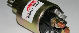
VR device
As it becomes clear, it is the VR that directs the bendix into engagement with the flywheel crown. The entire cycle of actions is based on the principles of electromagnetism.
The VR design includes a housing, an armature, a magnetic winding, contacts and a spring.
The anchor sits inside a hollow tube (core). The armature winding is a coil of wire. It enters the tube after an electromagnetic field is created in the bobbin. If the current stops flowing, the armature moves unhindered.
The magnet inside the VR is a pair of coils. One of them performs the function of a retracting element, the other - purely retaining functions. The first retractor coil is connected directly to the electric motor and the control terminal, and the second, the holding coil, is integrated with the fuselage and the control terminal.
It is clear that a magnetic field appears in the coil after a pulse arrives at the control terminal from the battery. As mentioned above, the armature begins its work from this, compresses the spring and at the same moment the bendix is pushed out, which engages with the flywheel crown.
After the engine starts, the power to the starter stops, and the armature returns to the initial exposure under the influence of the spring. The contacts open and the bendix disengages from the flywheel.