VAZ 2115 is one of the most worthy creations of the Volga automobile industry. In common parlance, this car is called a tag; it is truly considered one of the most popular and inexpensive cars on the domestic market, produced since 1997. The car earned its popularity quite honestly, since operation and repair do not pose any particular problems to the car owner. However, there are breakdowns that everyone who owns this wonderful car should know about. We will talk about the starter relay, its breakdowns and how to repair it.
Starter relay location
RELAY
If the starter on a VAZ 2114 does not turn, it is not at all necessary to remove it immediately. The fact is that the relay may be to blame for the malfunction, but not the retractor, but the one that is unloading and is usually installed either under the hood closer to the windshield, or under the steering shaft in the cabin. The relay is included in the electrical circuit running from the ignition switch to the VR, and is designed to protect the starter from overload.
But the question of where the starter relay is located on a VAZ 2114 often confuses many motorists, and this question is often asked on forums. The simple fact is that, depending on the year of manufacture of the car, the manufacturer slightly modified the electrical circuit and changed the arrangement of its elements. Then, when installing an alarm system, auto electricians could move the starter relay on the VAZ 2114 to another location.
How to find this tricky relay if it is not clear where it is located? It is necessary to remember how the connection diagram for the starter on the VAZ 2114 is arranged. There are only two supply wires on the VR - a constant voltage of 12 volts from the battery and a supply wire to the VR coming from the ignition switch. It is along the circuit of this wire from the starter that you need to follow, in the end, the wire will lead to the desired relay, in the diagram it is indicated as a locking switch.
Starter connection diagram
Depending on the year of manufacture and the engine control system, the relay might not be installed at all, for example, on cars produced before 2003. In cars produced before 2005, the relay block was installed in the engine compartment next to the vacuum brake booster.
Starter relay location
Later, on cars with a Europanel, this element was moved under the control panel, above the pedals in the cabin.
Blocks under the hood
There are 3 electronic control units in the engine compartment. The fuse box (1) and relay box (2) are located in the rear of the engine compartment, under the protective cover. And next to the battery there is an additional block with a relay (3).
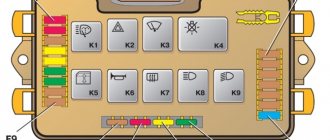
Fuse box
Scheme
Designation
| FV1 | 40A Engine cooling fan |
| FV2 | 30A Starter |
| FV3 | 50A Engine Cooling Fan |
| FV4 | 30A Heated tailgate glass |
| FV5 | 60A Automated gearbox Easytronic 80A Diesel engine glow plugs |
| FV6 | 40A Anti-lock Braking System (ABS) |
| FV7 | 50A Electric power steering |
| FV8 | 30A Electric blower fan |
REPLACEMENT
We figured out where the starter relay is located on the VAZ 2114, now all that remains is to find out how it can be changed. There are two options for replacing this part:
- With the removal and installation of the starting unit itself;
- Without removing the starter.
In any case, you should have the necessary tools:
- Combination key 13;
- A screwdriver (it would be better to have several of them - Phillips and slotted ones);
- Key for 10.
A set of keys is always necessary to have in stock. Let's look at how to replace the solenoid relay on a VAZ 2114 with removing and installing the starter (by the way, this is much easier to replace):
- Remove the battery terminals;
- Unscrew the two bolts securing the air filter housing (10mm wrench);
- Disconnect the connector of the air flow sensor (MAF);
- Unscrew the air pipe clamp and dismantle the housing;
- We pull off the wire chip of the solenoid relay (held on a plastic clip);
- Using a 13mm wrench, unscrew the nut securing the positive terminal;
- We unscrew the fastenings of the starter itself (it is secured with three 13 nuts);
- We take out the mechanism;
- With the starting device removed, use a 13mm wrench to unscrew the wire on the VR cover going to the stator winding;
- Using a screwdriver, remove the three screws securing the VR and dismantle this device.
Article on the topic: Installing rear disc brakes on a VAZ 2110
Now you need to install the new part and put everything back together in reverse order. That's it, the replacement of the retractor on the VAZ 2114 is completed. Of course, you can try to get to the relay mounting screws right in place without removing the starter, but it’s up to you to decide how easier it is to remove this device.
VAZ 2115 fuse diagram
The most common models are 3722010 (since 2004) and 21150 3722 010 10. The set of protective elements of electrical equipment in them is not very different from each other, but there are differences, and they are reflected in the decoding of the diagrams below.
The main mounting block under the hood of the car.
| F16 | 15A Direction indicators and relays - turn indicator and hazard warning switch (in turn indication mode). Turn signal indicator lamp. Rear lights (reversing lamps). Gearmotor and windshield wiper activation relay. Generator excitation winding (when starting the engine). Brake fluid level warning lamp. Oil pressure warning lamp. Carburetor air damper warning lamp. Parking brake warning lamp. "STOP" light display lamp. Coolant temperature gauge. Fuel level indicator with reserve indicator lamp. Voltmeter. |
| F3 | 10A Rear lights (brake lamps). Interior lighting. |
| F6 | 30A Electric windows for front doors. Relay for turning on electric windows. |
| F10 | 7.5A License plate lights. Engine compartment lamp. Instrument lighting lamps. Indicator lamp for external lighting. Heater lever illumination display. Cigarette lighter lamp. |
| F5 | 20A Electric motor of the engine cooling system fan, and its activation relay (contacts). Sound signal and relay for its activation. |
| F10 | 7.5A Left headlight (side light). Left rear light (side light). |
| F11 | 7.5A Right headlight (side light). Right rear light (side light). |
| F2 | 10A Turn signals and relays - hazard warning light interrupter (in hazard warning mode). Hazard warning lamp. |
| F4 | 20A Rear window heating element. Relay (contacts) for turning on the heated rear window. Plug socket for portable lamp. Cigarette lighter. |
| F15 | 7.5A Right headlight (high beam). |
| F14 | 7.5A Left headlight (high beam). Indicator lamp for turning on the high beam headlights. |
| F13 | 7.5A Left headlight (low beam). |
| F12 | 7.5A Right headlight (low beam). |
| Item no. | Power, A | What protects |
| 1 | 10 | Lamps for rear fog lights and PTF turn-on indicator |
| 1* | 10 | Headlight cleaner motor and relay (contacts). Headlight washer activation valve |
| 2 | 10 | Turn signals, breaker relay and hazard warning lamp |
| 3 | 7.5 | Interior lighting front, center, trunk Ignition switch Engine management system Brake lamps On-board computer |
| 3* | 7.5 | Rear lights (brake light) Body interior light |
| 4 | 20 | Cartridge for connecting a portable lamp Heated rear window (contacts) |
| 4* | 20 | Cigarette lighter Socket for portable lamp |
| 5 | 20 | Horn Cooling fan motor |
| 6 | 30 | Power windows Power relay (contacts) |
| 7 | 30 | Heater motor Windshield washer Headlight wiper motors (in operating mode) Cigarette lighter Glove compartment lamp Rear window heating relay (winding) |
| 7* | 30 | Headlight wiper motor Winding Heater motor Window washer Rear window wiper motor Windshield and rear window washer activation valve Cooling system fan activation Rear window heating relay coil Indicator lamp Glove compartment lighting |
| 8 | 7.5 | Right PTF |
| 8* | 7.5 | Left PTF |
| 9 | 7.5 | Left PTF |
| 9* | 7.5 | Right PTF |
| 10 | 7.5 | Left dimensions License plate lamps Engine compartment lamp Instrument lighting switch Illumination lamps for switches, instruments, cigarette lighter, ashtray, heater control levers Illumination panel for heater levers |
| 11 | 7.5 | Right dimensions |
| 12 | 7.5 | Right low headlight |
| 13 | 7.5 | Left |
| 14 | 7.5 | Left high beam headlight High beam indicator lamp |
| 15 | 7.5 | Right high beam |
| 16 | 15 | Turn signals, relay-breaker for turn signals and hazard warning lights (in turn signal mode) Reversing light lamps Lamp health monitoring relay On-board monitoring system display unit Instrument cluster Insufficient oil pressure lamp Parking brake activation lamp Brake fluid level lamp Battery low warning lamp Trip computer ( if installed) Generator field winding (in engine starting mode) |
| 17 | — | Reserve |
| 18 | — | Reserve |
| 19 | — | Reserve |
| 20 | — | Reserve |
Purpose of fuses
What fuses are on the VAZ 2114? The electrical circuit of this car is designed in such a way that in front of all the main electrical units there are chargers located in the fuse box.
VAZ 2114 fuse diagram
The connection diagram of these protective devices is shown in the figure.
- F1 - rated insert current 10 A - protects the fog lamps located at the rear.
- F2 - with a current of 10 A - these are left and right turn lights, an emergency warning light, a relay-breaker for turn lights and emergency lights.
- F3 - with a current of 7.5 A - protection of light bulbs in the cabin and trunk, trip computer circuits, ignition and brake lights, "Check engine" warning light.
- F4 - with a current of 20 A - protects switches located in the heating circuit of the trunk door glass and heating elements of this glass, “carrying” contacts.
- F5 - with a current of 20 A - protects the horn circuit and its switch, as well as the electric motor of the cooling system fan.
- F6 - with a current of 30 A - this is a circuit of electric windows and their switches with contacts.
- F7 - with a current of 30 A - a protective device for three electrical units - a heater, a windshield washer and a headlight cleaner. In addition, there is also a cigarette lighter, glove compartment lighting and winding for the heating switch for the trunk door glass.
- F8 - with a current of 7.5 A - is protection for the right fog light bulb located in front.
- F9 - with a current of 7.5 A - this is protection for the left fog light bulb located in front.
- F10 - with a current of 7.5 A - protects the indicator lights on the left side, the license plate number, the engine compartment light, the dashboard lights and switches with heating levers, as well as the indicator lights for the size.
- F11 - with a current of 7.5 A - protects the right-side headlight bulbs.
- F12 - with a current of 7.5 A - a protective device for the right low beam headlight bulb.
- F13 - with a current of 7.5 A - a protective device for the left low beam headlight bulb.
- F14 - with a current of 7.5 A - protects the left high beam headlight and the blue high beam warning light.
- F15 - with a current of 7.5 A - protects the right high beam headlight.
- F16 - with a current of 15 A - protects the light bulbs and the turn switch and hazard warning lights, the white reverse light, the power supply of the instrument cluster, the trip computer, the generator winding (at startup), the lights indicating low oil pressure, brake fluid and parking brake, battery discharge.
Explanation of the additional fuse and relay block
To turn on the main systems of any car, the manufacturer has designed the installation of auxiliary fuses. As a rule, they are located in the center console area. Each auxiliary module consists of several important relays and fuses.
In this particular case, the box is located to the left of the glove compartment, behind the side trim of the center console. To quickly access the box, you need to remove part of the plastic protection. The protection is attached to Phillips bolts, so you need to prepare the appropriate screwdriver.
Location of the additional fuse and relay box 2114, 2115, 2113 Additional unit in the passenger compartment Diagram of the additional unit
Table 3. Explanation of the additional fuse and relay block
| № | Current, A | Purpose (Fuses) |
| 1 | 15 | Main distribution relay |
| 2 | 15 | Controller power |
| 3 | 15 | Fuel pump |
| № | Purpose (Relay) | |
| K4 | Fuel pump | |
| K5 | Cooling fan | |
| K6 | Main system control relay | |
There are also options for other decryptions.
Explanation of the additional fuse and relay block
Relay:
Fuse:
f2 - main relay;
f3 - ECU (electronic control unit).
Relays that control the supply of current are present in the design of many vehicles. They are designed to perform a very important function - they turn on and off important electrical devices and mechanical systems of the vehicle. In simple terms, this is a device for supplying current to a required element.
The principle of operation of the VAZ traction relay
The starter coil, which receives power from the battery, creates a magnetic field that acts on the armature. It starts to move, compressing the return spring, which engages the bendix, which connects to the splines of the flywheel crown. The contacts of the elements close, the retracting winding remains without power, but the armature remains inside the coil, as it is held by a strong magnetic field. After the engine starts, the coil loses its power and the armature accordingly returns to its original position. In this case, the bendix itself disengages.
There are several options for checking the relay, which can be used to determine whether it is faulty.
In most VAZ cars, the relays are similar to each other, differing only in the way they are attached to the starter. And unfortunately, breakdowns that specifically affect the relay in 95% of cases end in its replacement. But still, before making this diagnosis, you need to make sure of one more serviceability, namely the functionality of the contacts at the place where the wire and terminal are soldered. Often, due to oxidation, the contact is lost, and by soldering it again, you can get rid of the problem of the starter relay breaking, provided that after this procedure the car is fully operational.
For a VAZ 2115, it is more cost-effective to replace the relay than to repair it to the point where it works properly.
Any service station will help you perform such a replacement, but this pleasure is relatively expensive. A much cheaper way would be to do everything yourself. If the owner of the car knows his ward 2115 inside and out, then such a replacement can be made independently without much effort, knowing the specific sequence of actions.
Before starting work, it is necessary to turn off the power from the battery, because while the electrical circuit is being created, it is prohibited to remove the starter, since you can completely burn out the entire wiring of the car.
- Clean the surface of the starter from dirt and dust;
- Unscrew the nut from the relay bolt and remove its contact;
- Unscrew the screws that secure the relay to the starter body;
- Remove the nuts from the end and divide the starter into 2 parts;
- Remove the old core and put a new one in its place;
- Reassemble all components in reverse order and check serviceability by connecting to the battery;
- Install the starter with the replaced relay on the car engine and check the operation.
Thus, following the exact recommendations, you can replace the starter relay yourself, but before you start removing and disassembling the starter itself, you need to check the indicators described above and make sure that the whole problem is in this particular part of the car, otherwise the wasted effort will not solve the main problem. Problems. If you haven’t identified the problem, then experienced service station employees will always help and do everything necessary for you!
Welcome, friends, to the DIY car repair website. Sooner or later, the time comes when your vehicle requires maintenance or repair, and a part such as a VAZ 2114, VAZ 2115 or some other starter is no exception.
Starter malfunctions occur quite often, either the solenoid relay malfunctions, or the bushings are broken, and it also happens that the VAZ 2114 starter does not turn at all.
Of course, there are different malfunctions and you can turn to specialists at a service station for help, but you can also do a small repair of the VAZ 2114 starter yourself, especially in some cases it is not difficult and you will even save a certain amount of money.
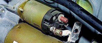
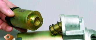
Starter relay (retractor) for VAZ-2114
This type of relay is located directly on the starter housing, and is controlled by supplying current from the ignition switch.
This type of relay is directly involved in starting the engine, regulating the clutch reaction between currents of different magnitudes (since the ignition voltage is less than the current supplied from the battery - approx.).
Solenoid relay location
It is not difficult to determine the location of the retractor; it is located directly on the starter and has two wires, the first, the smallest in size, comes from the ignition switch, and the second, the largest in size, comes from the battery.
The location of the wires is indicated by arrows.
The relay is located directly on the starter housing.
Relay operating principle
The operation of this relay is as follows:
- When the battery supplies current to the starter coil, due to the magnetic field, the coil acts on the armature.
- When the armature moves, it clamps the spring, from which the bendix is connected to the splines.
- When the contacts close together, the engine starts, and all connections return to their places, disconnecting the fixation points.
Solenoid relay malfunctions and their symptoms
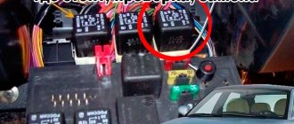
You can first see if there are problems with the solenoid relay visually, since there may be traces of corrosion on the wires, and as a result, the incoming current may simply not pass to its destination. If cleaning these contacts does not lead to anything, then we move on to inspecting the 4-pin relay, usually located on a bolt in the engine compartment.
The relay location is indicated by a red marker.
Starter, ignition, rear fog lamp relay
In order to carry out quick checks and repairs, the ignition system relay is installed under the front dashboard of the car, behind the hood release handle. It is located just below the central dashboard. The module is closed with a plastic plug, which must be opened slightly to test for functionality.
Starter, ignition, rear fog lamp relay
Next to the indicated relay, there is a similar one for the rear fog lights and the starter.
The main task of the relay when igniting is to reduce the applied load to the contacts. When the engine starts, the relay turns off some electrical circuits in the vehicle system. The system is used not only in injection, but also in carburetor engines.
In the event of a malfunction or malfunction in the ignition system, it is necessary to monitor the operation of the relay. For this purpose, open the box and carefully remove the desired element. It is attached using contacts to special grooves. The first thing to do is look at the oxidation of the contacts, if necessary, clean them with a soft cloth or treat them with a special liquid.
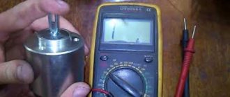
To check functionality, you need to use a regular multimeter. We connect to incoming connections and check the numbers. If there is no short circuit when current is applied, it means the element is not working. Replacement is carried out in a similar manner. It is necessary to use a standard element with the number of amperes indicated on the housing.
Opening the trunk using the car alarm key fob
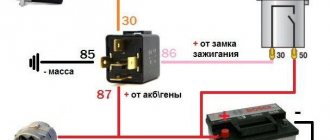
If your car has an electric trunk drive, you can connect to it with a car alarm to open it using the alarm key fob. If the alarm outputs a low-current signal to open the trunk (and most often this is the case), then we use this circuit.
First of all, we find the wire to the trunk drive, where +12 Volt appears when the trunk is opened. Let's cut this wire. We hook up the end of the cut wire that goes to the drive to pin 30. We hook up the other end of the wire to pin 87A. We connect the alarm output to contact 86. We connect contacts 87 and 85 to +12 Volts.
Now, when a signal is sent from the alarm to open the trunk, the relay will work and “plus” will go to the trunk electric drive wire. The drive will operate and the trunk will open.
These are just a few wiring diagrams using relays. You can find a few more diagrams using relays on the website in the category trick diagrams and in the section diagrams for connecting to the central lock.
Methods for solving the problem
Now that the main causes have been sorted out, you can move directly to elimination methods.
So, let's look at what ways to deal with the malfunction.
Fuse
Disassembled dashboard while searching for fuse and cigarette lighter faults.
The most common cause of malfunction or inoperability of the electrical circuit of individual elements is the notorious fuse.
This is where you need to look for the cause first.
But it does not always withstand the load placed on it. Thus, frequent and large use of additional devices can lead to frequent burnout of this element. Therefore, to check it is worth removing and inspecting the fuse itself. If necessary, the element is replaced with new ones and if everything works, then the reason has been found. But if the problem does not go away, then you should look for it in other places.
Contacts
Checking the contact group of fuses for malfunction
A contact group is another common cause of a non-functioning electrical circuit. In most VAZs, the connecting contacts of the fuse with the block or in the circuit of the wire block oxidize or burn out, and molten plastic can interrupt the contacts.
To troubleshoot the problem, you need to check all the contact blocks of the wires that go from the radio and cigarette lighter to the fuse box. So, it is oxidation and insufficient contact that can lead to the inoperability of the elements.
Wiring
Another reason could be broken power wires. So, in order to find and fix the fault, you will need a tester that will test the wiring and find a broken wire. It is recommended not to fasten the wire using the old “old-fashioned method” using electrical tape, but to replace it with a new one. This will take little time, so it’s better to do everything in such a way that you get a short circuit and cause big problems.
Short circuit
Location of frequent failure of the cigarette lighter socket.
The worst thing that can happen is a short circuit. The reason for this phenomenon is that frequent use of the cigarette lighter loosens the socket and this can lead to the contacts crossing and causing a short circuit.
The standard cigarette lighter is just a disaster for the VAZ-2114.
Here, the treatment for the malfunction is quite simple - replacing the socket. But, often motorists take a low-quality and cheap product, which repeats the procedure after a short time.
Bulb
Cigarette lighter illumination at night VAZ-2114.
The backlight bulb is located in the same electrical circuit, so the burnout of this element causes a malfunction of the radio and the cigarette lighter at the same time. So, if you replace the element, you can correct the situation.
Checking work
Sometimes, despite more than obvious signs of breakage or wear of the retractor, in reality everything turns out to be wrong. The car may behave similarly with some other malfunctions.
Therefore, in order to figure out whether the relay works or not, and also who is the real culprit for the violation of the functionality of the system, we will conduct several checks.
- Check the starter. Turn the ignition key. The starter should begin to turn, and the relay should make a characteristic click. If the starter is not doing its job, replace it. Relyukha has nothing to do with it in this case.
- Check the solenoid relay. To do this, there are two copper bolts on the back cover. Two contacts are attached to them. If the starter starts turning, then your relay has definitely failed and needs to be replaced. In this case, you should not remove the starter, which will allow you to get more accurate test results.
- If you have removed the starter, the check is performed slightly differently: Connect the contact wire of the retractor relay to the positive terminal of the battery;
- The second contact connects the starter ground and the battery charger;
- When the contacts are placed on the relay terminals, the relay should turn on with a characteristic click;
- If the operation is too slow, uncharacteristic, check the condition of the contacts. They often burn out or oxidize.
https://youtube.com/watch?v=vhq_2EEiDzU
Signs of breakdown
If, when you turn the ignition key, the electric starter does not spin, but you can hear soft clicks of the relay contacts operating, then the cause of the car malfunction is the starter. You can verify this by connecting it directly to the battery, bypassing this electric relay. If clicks are not heard, and the starter is working properly, then it’s time to change it.
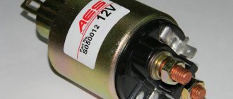
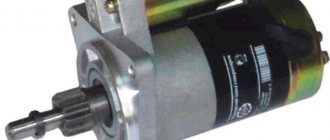
VAZ 2115 starter relay
The most likely cause of starter failure is not mechanical damage, but electrical damage.
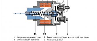
Block diagram of the starter device. The numbers indicate: 12 - drive gear; 11 — freewheel; 10 - spring; 9 — planetary gearbox; 8 - permanent magnet; 7 - anchor; 6 — brushes; 5 - collector; 4 - traction relay
, you need to keep in mind that the starter traction relay has nothing to do with the starter relay!!; 3 — contact for connecting the positive wire; 2 — drive lever; 1 - armature shaft;
The mechanical part of the starter of the VAZ 2115 car is a retractor mechanism, which works properly throughout the entire operation of the car, only in rare cases does it break down, and only on cars with high mileage. Electrical faults in the starter can be caused by relays, oxidized wire connections, short circuit and other factors. At the first unsuccessful engine starts, most people look for a problem in the starter, which is not always correct. The operation of the starter directly depends on the relay, contact connections and the availability of the necessary electricity. To check whether the electric starter is working, you can power it directly from the battery by connecting the positive wire from the terminal. In this way, you can start the engine to continue driving if the starter power supply system is faulty. Many people try to find a starter relay in a VAZ 2115 car, where the vehicle’s electronic system unit is located, but the search does not produce results. This is due to the simple reason that it has been missing since release. Perhaps the VAZ manufacturer is already equipping new series of cars with a starter relay, but previous versions of these cars were produced without it. This is not critical, since the cost is negligible, and the benefits are visible instantly, and you can install it yourself, without the skills of an auto electrician. Many owners of VAZ cars install additional equipment, as this improves the characteristics of the car.
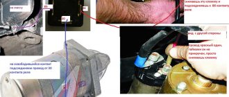
Photo of the engine compartment of a VAZ 2115 car. From this photo you can see the starter relay marked with an arrow.
You can install the VAZ 2115 starter relay where the main electronics unit is located, or in another convenient place. Why is it necessary to install an additional starter relay for a VAZ 2115 car? An additional relay ensures more stable operation of the starter when additional electrical equipment is turned on. Thus, the starter works even with a weakly charged battery, the lights on and at low temperatures.
- The VAZ 2115 starter relay should not be confused with the retractor relay, which is located on the starter and performs the function of pushing and retracting the mechanism for engaging the starter teeth and the flywheel. Thus, the usual starting of the car occurs. Malfunctions of the solenoid relay are expressed in the following manifestations:
Such manifestations are typical of breakdowns of the solenoid relay, which can be corrected by removing the starter and replacing the relay.
Repair of VAZ 2115 starter retractor relay
The presence of one of the above reasons when trying to start the engine indicates the need for repairs, which you can do yourself.
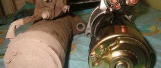
Photo of the process of replacing the starter relay on a VAZ 2115 car.
This will require a trestle and some tools. First you need to remove the starter by unscrewing the mounting bolts and first turning off the power to the battery. Remember - the main thing is to ensure the safety of repairs. After successfully removing the electric starter, you need to unscrew the bolts of the retractor relay. In most cases, the solenoid relay is not removable, but it can still be repaired. To do this, you will need a screwdriver, a soldering iron, a copper winding wire, a core, which upon inspection may turn out to be intact and unharmed. In this case, there is no need to change it. Having soldered the wires with a soldering iron, you can begin flaring the coil body. By disassembling the coil, you can determine its damage and replace the elements in need. https://www.youtube.com/watch?v=UpVJSYub72s Assembly is carried out in the opposite order, adhering to the sequence of screwing the parts. Also read other reviews
Starter and additional relay VAZ 2114: why the starter does not turn
The starter on the VAZ 2114 is the engine starting device; without it, the engine can only be started from a pusher or in tow. Its failures cause a lot of trouble for car owners, but the reason for the inoperability does not always lie in the starting mechanism itself - there are other breakdowns, for example, a non-working relay.
Starter
Trigger device
The starter on a VAZ is an electric motor with a mechanical drive for engagement with the flywheel of an internal combustion engine (ICE). The device itself consists of the following parts:
- Main building. It is a metal hollow cylinder, inside of which the electric motor parts are located;
- Stator. The stator is a winding made of thick copper wire, between the turns of which steel cores are placed. The winding is located inside the housing along its walls;
- Rotor. The rotating part of the mechanism, steel plates made of electrical steel are assembled on the shaft, and a winding is located inside the plates. It is also called “anchor”. The armature rotates in the housing bushings - front and intermediate; the rear support of the entire shaft is a bushing in the gearbox housing. There is also a collector on the rotor, which is a set of plates. A magnetic field is created on the collector, which sets the armature in motion;
- Bendix. A gear device that meshes with the flywheel of an internal combustion engine and ensures engine rotation. Placed on the rear of the rotor shaft;
- Brush unit. In model 2114, there are 4 brushes in the assembly. The brushes interact with the rotor commutator, and it is they who create the electromagnetic field;
- Solenoid relay. Unlike a conventional relay, the solenoid relay performs two functions at once - it closes and opens the contacts of the electrical circuit, and with the help of the core it moves the bendix gear to engage with the flywheel of the internal combustion engine.
Malfunctions
There are various signs of a starter malfunction on a VAZ 2114:
- The starter does not work at all, that is, it does not show any signs of life. The stator or rotor winding may burn out and power may not be supplied to the electrical part of the device;
- The starter turns, but does not engage; often the Bendix idles, not engaging with the flywheel. Usually the cause is the bendix itself - it should only rotate in one direction on its axis;
- The starter does not operate when the VAZ 2114 key is turned. If dry, quiet clicks occur, then both the VR solenoid relay and the relay responsible for turning on the circuit by turning the key in the ignition switch may be faulty. If the VR is faulty, the clicks are usually louder;
- The starter turns slowly, but can stop quickly. The stator or armature winding is short-circuited, the rotor has play in the bushings. There may also be a bad weight of the internal combustion engine with the body or a weak battery, but this does not apply to the starter;
- The engine starts with a grinding or crunching sound. Most often, such a start indicates wear of the teeth on the Bendix gear or the teeth of the engine flywheel.
RELAY
If the starter on a VAZ 2114 does not turn, it is not at all necessary to remove it immediately. The fact is that the relay may be to blame for the malfunction, but not the retractor, but the one that is unloading and is usually installed either under the hood closer to the windshield, or under the steering shaft in the cabin. The relay is included in the electrical circuit running from the ignition switch to the VR, and is designed to protect the starter from overload.
But the question of where the starter relay is located on a VAZ 2114 often confuses many motorists, and this question is often asked on forums. The simple fact is that, depending on the year of manufacture of the car, the manufacturer slightly modified the electrical circuit and changed the arrangement of its elements. Then, when installing an alarm system, auto electricians could move the starter relay on the VAZ 2114 to another location.
Article on the topic: Repair of the VAZ 2114 exhaust system: replacing the muffler
How to find this tricky relay if it is not clear where it is located? It is necessary to remember how the connection diagram for the starter on the VAZ 2114 is arranged. There are only two supply wires on the VR - a constant voltage of 12 volts from the battery and a supply wire to the VR coming from the ignition switch. It is along the circuit of this wire from the starter that you need to follow, in the end, the wire will lead to the desired relay, in the diagram it is indicated as a locking switch.
Starter connection diagram
Depending on the year of manufacture and the engine control system, the relay might not be installed at all, for example, on cars produced before 2003. In cars produced before 2005, the relay block was installed in the engine compartment next to the vacuum brake booster.
Starter relay location
Later, on cars with a Europanel, this element was moved under the control panel, above the pedals in the cabin.
Where is the Starter Relay for VAZ 2115 Injector?
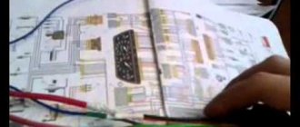
where is the ignition relay on the VAZ 2115 and how to find it
After the first unsuccessful attempts to start the car engine using the ignition key, without hearing the usual sounds of the starter, most car owners look for the cause of the malfunction in its breakdown. But most often the cause is the ignition relay.
Why do I need an ignition relay
This item was installed on previous VAZ car models. With all this, this may not be the case for earlier modifications of 2115. It is located in the starter circuit on VAZ-2115-01, 20, 21, 22 (injector, carburetor).
This section has different names: ignition relay, starter start, starter disable, ignition off or ignition switch, main relay.
But in any case, its purpose is the same - to make it easier to start the engine and protect the starter from wear, it turns off the power to the electric starter after starting the engine, limits the currents flowing through it, protects the contacts in the ignition switch or turning the key from caking while the engine is running.
In addition, it allows you to start the starter when the vehicle's electrical equipment is turned on and the battery charge is low.
There are no fuses in the ignition circuit of this model.
Thus, this cheap part saves you from expensive repairs and makes starting the engine easier.
This part should not be confused with the repeater, located specifically on the starter and designed to control (extend or push) the starter clutch mechanism and the flywheel teeth.
install relay
to the starter
Until 2110.
Signs of breakdown
If the electric starter does not turn when you turn the ignition key, but you hear soft clicking sounds from the relay contacts, the problem with the vehicle is the starter. You can test this by attaching it specifically to the battery, bypassing this electrical relay. If you can't hear the clicks and the starter works, it's time to change it.
Where
Where is the relay? ignition of VAZ-2115? It is located in the cabin, to the left of the steering column, under the dashboard. To see this you need to remove the instrument panel. Next to it, to the left of it, is a relay for turning on the rear fog lights. They are bolted to the body stud using a “10” nut and located in a special trim.
The relay also controls the washer, auto heater, rear window heating and some other low-current circuits. If these parts of the car are not working properly, you need to check the condition of that part.
The type of electric ignition relay is 90.3777-10, it has four contacts, the control voltage is 12 volts. When purchasing a new relay, be careful: the five-pin 24-volt counterparts have a similar appearance. Self-repair of this part is not profitable due to its low cost.
Video: “Ignition relay VAZ-2115: Where is it located? "
If installed independently
The previous owner of the car, in the absence of such a standard part, could install it himself. These installation kits are sold at car dealerships. In this case, the electrical relay can be located not only in the “usual” place. Finding it without calling the previous owner will not be easy.
If this part breaks On the way, you can start the car by closing contacts 87 and 30 (the layout and layout are based on the upper part of the relay housing diagram). In this case, the use of the machine is permitted without any restrictions. But at the first opportunity, be sure to remove the damage. The operation of the VAZ-2115 ignition system directly depends on the relay.
There is a special offer on our website. You can get a free consultation with our corporate lawyer by simply submitting your question in the form below.
If you installed it yourself
The previous owner of the car, in the absence of such a standard part, could install it himself. Such installation kits are sold in car dealerships. In this case, the electric relay can be located not only in the “standard” location. Finding it without calling the previous owner will not be so easy.
If a breakdown of this part occurs on the way, then you can start the car by closing contacts 87 and 30 (the location and circuit diagram are printed on the top of the relay housing). In this case, you are allowed to use the machine without any restrictions. But at the first opportunity, be sure to fix the breakdown. The operation of the VAZ-2115 ignition system directly depends on the relay.