Many farmers cannot imagine working in the fields without a tractor. They are interested in how to make a trailer for a walk-behind tractor with their own hands from the rear beam 2108 for transporting building materials or other items.
Rear suspension device
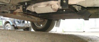
The rear wheel suspension is torsion-lever type.
Its design is simple and reliable, and maintenance during vehicle operation is reduced to a minimum and consists of inspecting suspension components and parts to check their condition and fastening. The guide element of the suspension is a beam consisting of two longitudinal arms 2 (Fig. 74) and a connector 19, welded together through reinforcements. The lever connector is significantly shifted forward from the wheel axis; it has a U-shaped cross-section, which has high bending rigidity and low torsional rigidity. Due to the displacement of the lever connector from the wheel axis and thanks to the specified cross-section, the connector, twisting, works like a torsion bar, ensuring partial independence of the movement of each wheel.
Rice. 74. Rear suspension assembly:
1 — rear wheel hub; 2 — rear suspension lever; 3 — suspension arm mounting bracket; 4 — rubber bushing of the lever hinge; 5 — hinge spacer; 6 — suspension arm mounting bolt; 7 — body bracket; 8 — support washer for fastening the shock absorber rod; 9 — upper suspension spring support; 10 — spacer spring; 11 — insulating gasket for the suspension spring; 12 — rear suspension spring; 13 — shock absorber rod mounting cushion; 14 — compression stroke buffer; 15 — shock absorber rod; 16 — shock absorber protective casing; 17 — lower support cup of the suspension spring; 18 — shock absorber; 19 — lever connector; 20 — wheel hub axis; 21 — hub cap; 22 — wheel hub fastening nut; 23 - sealing ring; 24 — bearing washer; 25 — hub bearing; 26 — brake shield; 27 — retaining ring; 28 — dirt-reflecting; 29 — suspension arm flange; 30 — shock absorber bushing; 31 — lever bracket with an eye for attaching the shock absorber; 32 — rubber-metal hinge of the suspension arm.
Behind the lever connector, a space is formed in which the spare wheel and a spacious gas tank are located. This is another advantage of the front-wheel drive car's layout and the adopted rear suspension design.
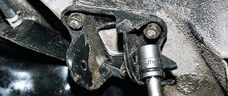
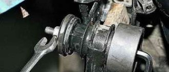
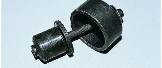
Trailing arms 2 are made of pipe. Welded to the rear of the levers are brackets 31 with eyes for attaching shock absorbers, as well as flanges 29 to which the rear wheel hub axles 20 and wheel brake shields 26 are bolted. At the front, each lever has a welded bushing into which a rubber-metal hinge 32 is pressed, consisting of rubber 4 and metal 5 bushings. A bolt 6 passes through the spacer sleeve 5 of the hinge, connecting the suspension beam arm with a stamped bracket 3, which is attached to the body bracket 7 with welded bolts, nuts and washers.
The spring 12 of the suspension is made of spring steel of round section. It is installed on shock absorber 18. Its lower part rests on cup 17, welded to the shock absorber reservoir, and its upper part, through an insulating rubber gasket 11, rests on the upper support 9, which is welded to the inner arch of the body.
The compression stroke buffer 14 is made of polyurethane. It is mounted on the shock absorber rod inside the suspension spring. From above, the buffer rests against the cover of the protective casing 16, and when put into operation, it rests against the buffer support, which is put on the upper part of the shock absorber reservoir. The casing 16 protects the shock absorber rod 15 and the compression stroke buffer from mechanical damage and contamination.
Other design methods
Pay attention to models with a more complex design. This process usually takes place in several stages.
Trailer base.
To begin with, all the necessary materials are prepared and a design drawing is drawn up. It must indicate the dimensions of all parts and, most importantly, the body. It is also important to consider how much cargo you are going to carry. Based on this, calculations are made. Let's say you are transporting potatoes, the crop weighs about 0.5 tons. This means that you need a large trailer. Having decided on the size of the device, count the exact number of consumables so as not to overpay extra money.
Make sure you have a welding machine on hand during construction, because regular bolts cannot hold the base of the trailer. Their heads may fall off.
The next step is to make the main elements. A ready-made template can easily pass for the main part. A trolley for transporting cargo must have an increased margin of safety, which will allow it to be used on complex relief surfaces.
The only negative is the fact that the body does not have folding sides at all. If you want, you can improve the cart a little by making folding walls. You can also make side loops with straps on the body that will secure materials or products during transportation.
One of the most important processes in manufacturing is considered to be the arrangement of the chassis of a trailer for a mini-tractor.
You can buy a set of wheels and springs in a store or use old ones (from Zhiguli or other cars that have fallen into disrepair).
When modeling the wheel axle, you can use a steel rod. Its diameter should be 30 mm, and the length should be chosen so that the wheels do not come out when assembled. Your agricultural device is ready. If you wanted to know how to make a trailer from a VAZ 2109 beam, then the principle of action is the same.
Rear suspension parts
1 – wheel hub; 2 – suspension arm mounting bracket; 3 – silent block; 4 – shock absorber casing; 5 – compression stroke buffer; 6 – casing cover; 7 – support washer; 8 – shock absorber cushions; 9 – spacer sleeve; 10 – shock absorber; 11 – rubber gasket; 12 – rear suspension spring; 13 – lever connector; 14 – lever of the rear suspension beam; 15 – shock absorber mounting bracket; 16 – lower spring support cup; 17 – rod; 18 – upper spring support cup.
Final assembly
To assemble, follow these steps:
- Install the hub onto the axle.
- Place the washer and tighten the nut by hand.
- Install the brake drum and tighten the studs.
- Place the wheel and lower the car.
- Tighten all threaded connections.
- Place the nut on the hub.
Reassembling the entire assembly occurs in the reverse order. The hub nut must be tightened to a torque of about 200 N*m.
Volgaavtoprom rear wheel hub assembled with axle, bearing, washer and nut 2108-21099, 2113-2115
Composition: 3D model
Software: STEP / IGES 13 SP2
Date of: 2018-09-28
Views: 603
Description of design
The rear suspension is with 12 coil springs and 10 double-acting hydraulic telescopic shock absorbers.
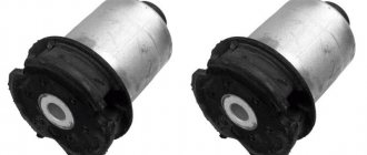
The main load-bearing element of the suspension is a beam consisting of trailing arms 14 and a connector 13, welded together through reinforcements. At the rear, brackets 15 with eyes for attaching shock absorbers 10 and flanges for attaching the rear wheel axles and brake shields are welded to the suspension arms. At the front, the levers 14 are equipped with welded bushings with silent blocks 3 pressed into them. A bolt passes through the central bushing of the silent block, connecting the lever to the bracket 2. Three welded bolts are provided to secure the bracket to the body spar.
The suspension spring 12 rests with its lower end on a cup welded to the shock absorber reservoir, and with its upper end, through a rubber gasket 11, on a support welded from the inside to the body arch.
The lower eye of the shock absorber is bolted to bracket 15 of the suspension arm, and its rod is secured to the upper support of the suspension spring through two rubber pads 8 (one at the bottom of the support, the other at the top) and a support washer 7 (under the nut).
The rear suspension springs are divided into two stiffness classes according to their length in the free state and under load: A (more rigid, “high”) and B (less rigid, “low”). Springs of the same class must be installed on the front and rear suspensions. But in exceptional cases, if class A springs are installed in the front suspension, class B springs can be installed in the rear suspension (but not vice versa!). The quality of the springs can be fully assessed by the performance of the suspension on the car. If the suspension often “breaks through” to the bump stops on uneven roads or sags under load, stiffer springs should be installed. When replacing springs, do not forget to check the serviceability of the shock absorbers - after all, it is the shock absorber-spring pair that largely determines the characteristics of the suspension.
Summarizing
Drawing a conclusion on this topic, it can be noted that any walk-behind tractor becomes even more functional when a trailer is attached to it. It is an integral device for transporting cargo. It is very easy to make such a device at home.
There is no need to buy new parts for assembly, because you can take unused parts of an old VAZ 2109 or other brands. To avoid corrosion, treat metal elements with a special coating or simply paint them.
Hi all. I'm going to make a trailer on the VAZ-2109 beam. The trailer will be used on the farm, and only driven around the village) I can’t find drawings or examples of how to do this) There are probably Kulibins here who have already made something like this from beam 2109, I’ll be grateful if you help)
Comments 88
I converted the beam to 10, I had to cut it and increase it by 17 centimeters, I’m moving more than two tons
Factory - on what trailer?
Yes. This will probably be more correct)
So probably under a ton.
In fact, the beam is of little interest to me since I will use it either from a Fiat Ducato or from a similar truck. More question about the actual frame. I turned the 40*40 profile on the base and somehow it didn’t inspire confidence. Looks a bit flimsy)
Well, not like that! In general, the total weight of the VAZ 2109 is 1350 kg. In this case, the main load is on the rear axle. This is an iron 700kg.
Yes. After writing the question, I noticed this information and redid the question)
How many times have you tried to drive it? Will it hold a ton?
Rubber bands are not necessary, but if you don’t hold the shock absorber against the release, it will either tear off or break; I would put a chain between the beam and the frame. The tension is such that a fully finished trailer without a load would stand on its wheels and the chain would sag slightly. Everything is based on the experience of Kzap 8140. If the spring is long, you can shorten it, but take your time.
Kind. You reacted quickly. Center the bottom and set the clamping limit.
I think it’s not necessary, but this is not an option in your case, because... For such a powerful trailer you need at least three of these shock absorbers on each side.
And the spring didn't fall out
In the photo you have a spring lying on the shock absorber, so when compressed it will work haphazardly. You need support cups with clear fixation of the springs, or weld 3-4 cm of pipe with a diameter equal to the inner diameter of the spring to the support cups. Well, limiting the suspension travel with a chain, like on the 8140 gearbox, see on the internet. There may be other options
Something with the spring supports didn’t turn out very well! Under load they will work at random.
On mine I only used the hubs from this beam... I welded a pipe to them and inserted them into the suspension of my trailer... I did this only to install larger wheels... I think it would be ideal to use springs... the simplest and most reliable design.www.agromts. ru/01/Technik…zav/mord/avto828512w_.jpg You can also try using shock absorbers from a moped. They come with springs but the load capacity is maximum 300kg shopingbasket.ru/img/2015/070515/2803083
I’ll soon start turning this thing into reality) I’ll probably start in early April) my brother will come, he has some other plans about this) I’ll share with you))
I converted the factory one to fit this beam
mmm, show me if you can_)))
www.drive2.ru/l/8177850/ They did a tackle for me, though, but also a similar trailer)))
I wanted to do the same. The part with the wheels was cut off from the beam. We welded a pipe there (between the wheels) - a beam. We got the springs from the Muscovite = shock absorbers. She turned out to be an excellent worker. They calmly carried 15 bags of cement)))
I wanted to do the same. The part with the wheels was cut off from the beam. We welded a pipe there (between the wheels) - a beam. We got the springs from the Muscovite = shock absorbers. She turned out to be an excellent worker. They calmly carried 15 bags of cement)))
No))) at that time I didn’t even have the Internet. I can look for photos.
How can I put photos in messages?
if in the comments, then click on reply, on the right there is send and next to it is a camera button, there you insert a photo)
No tut. It used to be.
How can I put photos in messages?
and if in personal messages, then there is also a camera there) as I wrote above)))
design features of the rear suspension of VAZ 2108, VAZ 2109, VAZ 21099 cars
The rear suspension beam consists of two trailing arms 13 (Fig. 6.4) and a connector 12, which are welded together through reinforcements. In the rear part, brackets 14 with eyes for attaching shock absorbers and flanges 15 are welded to the suspension arms, to which the rear wheel axles are bolted together with the wheel brake shields. In front, bushings 16 are welded to the rear suspension arms, into which rubber-metal hinges 1 are pressed. Bolts pass through the hinges connecting the suspension arms to stamped-welded brackets 2, which are attached to the body side members with welded bolts. The suspension springs 11 rest with one end on the shock absorber cup 9, and with the other end, through an insulating rubber gasket 10, in a support welded to the inner arch of the body. The rear suspension shock absorber is hydraulic telescopic, double-acting. The rear suspension shock absorber is attached with bolt 9 (Fig. 6.5) to the suspension trailing arm bracket. The rod is attached to the upper support 5 of the suspension spring through rubber pads b and a support washer 3. The shock absorber parts are shown in Fig. 6.6. Hub 13 (see Fig. 6.5) has a double-row angular contact bearing 12, similar to the front wheel hub bearing, but smaller. Unlike the front wheel hub, on which the inner bearing ring is installed with guaranteed interference, on the rear wheel hub, bearing 12 on axle 14 has a transitional fit.
Rice. 6.4. Diagram of the rear suspension of a VAZ 2108, VAZ 2109, VAZ 21099:
1 — rubber-metal hinge; 2 — rear suspension arm mounting bracket; 3 — shock absorber casing; 4 — compression stroke buffer; 5 — casing cover; 6 — support washer; 7 — shock absorber cushions; 8 — spacer sleeve; 9 — shock absorber; 10 - insulating gasket; 11 — rear suspension spring; 12 — lever connector; 13 — rear suspension beam arm; 14 — shock absorber mounting bracket; 15 - flange; 16 — lever bushing
Rice. 6.5. Mounting the rear shock absorber VAZ 2108, VAZ 2109, VAZ 21099 - rear suspension device:
1 - protective casing; 2 — compression progress buffer; 3 — support washer; 4 — spring insulating gasket; 5 — upper support cup of the suspension spring; 6 — shock absorber rod mounting pads; 7 — lower spring support cup; 8 – rear shock absorber; 9 — rear shock absorber mounting bolt; 10 — wheel hub axle mounting bolt; 11 — brake drum; 12 — hub bearing; 13 — wheel hub; 14 — hub axis; 15 — hub nut; 16 — retaining ring; 17 - locating pin
Rice. 6.6. Rear shock absorber device for VAZ 2108, VAZ 2109, VAZ 21099:
1 — compression valve body; 2 — compression valve discs; 3 — throttle disk of the compression valve; 4 — compression valve plate; 5 — intake valve spring; 6 — compression valve cage; 7 — recoil valve nut; 8 — recoil valve spring; 9 — recoil valve plate; 10 — washer; 11 — recoil valve disc; 12 — throttle disk of the recoil valve; 13 - piston; 14 — piston ring; 15 — bypass valve plate; 16 — bypass valve spring; 17 — restrictive plate; 18 — spacer sleeve; 19 - reservoir; 20 - rod; 21 — compression buffer support; 22 - nut; 23 — oil seal cage; 24 — rod protective ring; 25 — oil seal; 26 — sealing ring of the tank; 27 — rod guide bushing; 28 - cylinder; 29 — silent block
What is a hub and why is it needed?
In mechanics, a hub is the central part of a part with a hole (usually it looks like a keyway) for fitting onto a shaft, in particular onto a trunnion.
Also, spokes are attached to the hub. This is what the hub looks like
This important spare part ensures the movement and controllability of the car. Its main functions:
- wheel mount;
- its rotation;
- transmission of torque from the transmission to the wheel, that is, the connection between the shaft and the disk.
Hubs are divided into two types - front wheel hubs and rear wheel hubs. They differ in location: the former can be found in the front wheels, and the latter in the rear.
Rear wheel hub
What drives can be installed
When planning to replace old steel wheels with alloy wheels, you should choose either original products or products from well-known manufacturers who care about the quality and safety of their products.
Alloy wheels combine the following useful properties: they are lightweight, practical to use, endowed with sufficient strength and have an attractive appearance, which is aimed at transforming the entire appearance of the car.
The most common among alloy wheels are aluminum products. This is due to the fact that they are resistant to corrosion, meet strength requirements and, in comparison with other alloy wheels, remain relatively inexpensive.
Replacement
To replace you will need:
- New rear silent blocks;
- A small wooden beam;
- A device for pressing in a silent block (you can do the job without it);
- Open-end wrenches;
- Socket wrenches;
- Spanners;
- Hammer.
Dismantling works
When everything is ready, you can start working.
- Place the car on a level surface in the garage above a pit or overpass. Be sure to place wheel chocks and shoes under the wheels. All for your safety.
- It is better to remove the rear wheel to make it easier to work.
- But it is not at all necessary to remove the rear beam. Just complicate your work with unnecessary dismantling processes.
- On the left side of the driver is the pressure regulator rod for the rear brakes. It will disturb you while you work, so we advise you to remove it. This is done by removing the locking bracket of the rod and the handbrake cable. You will remove the latter from the right side from the mount.
- Unscrew the nut from the bolt with a 12mm wrench that holds the rear beam to the bracket. This may cause problems. Place a socket wrench on the driver to increase leverage on the fastener. Remove the bolt, lift the car with a jack and move the beam down. It will come out of the eyelet this way. Do not overdo it to avoid damaging the nearby brake hose. If you press too hard on the pry bar while moving the eye, you risk breaking the hose.
- Take a pre-prepared wooden block and insert it between the body and the beam. This must be done so that the beam is below the eye.
- Using a hammer and a drift (regular metal tubing will do), knock out the old worn bushings. By the way, if you come across such a concept as “fungi”, don’t worry. This is what car enthusiasts often call these bushings because of their external similarity.
- Clean the seat from accumulated dirt and rust. Be sure to lubricate the areas with soapy water. Without it, it will be difficult to press in new silent blocks. Or use a simple dish detergent. Under no circumstances should you lubricate the seats with grease or oil, as these substances will soon begin to corrode the element.
- Now it presses in new elements. Ideally, you should have a special pressing tool. If you don't have one, use a regular hammer.
- Take out a wooden block.
- Armed with a second jack, lift the beam and insert the mounting bolt into place and tighten it with a nut.
- Reinstall the rear wheel and lower the car to the ground.
Only upon completion of all these stages can the bolts of the new silent blocks be tightened until they stop.
Such an operation should not cause any special problems, so it is not at all necessary to go to a service station and spend extra money.
How to remove a rear wheel hub and install a new one
The replacement procedure looks like this:
1. The car is installed on a lift. 2. Next, unscrew the nuts and remove the caliper. 3. Remove the hose, brake disc, and steering lever. 4. Release the hub from the ball joints and remove the strut fasteners. 5. Install a new bearing, return all parts to their place.
The following types of hubs exist:
Designed for the rear wheels of front-wheel drive vehicles.
Used in the front wheels of front-wheel drive cars.
This type is needed for the front wheels of rear-wheel drive cars.
How to make a trailer for a walk-behind tractor with your own hands
Here we will explain how to make a homemade trailer for a walk-behind tractor, consider its components and drawings that will help you make your trailer.
A trailer for a walk-behind tractor can be considered as a combination of a frame, body, wheels and hitch. The frame is made of rectangular and round steel pipes, fastened with steel corners using a welding machine.
All this is necessary for summer residents, because you will probably use the trailer on the farm, off-road.
For the bottom and sides of the body, you can use professional flooring, sheet metal 1 mm thick, or boards 20 mm thick. Using boards, you need to fasten them together with steel corners, and attach the finished body to the frame with bolts. For ease of loading and unloading, the sides are folding, we will mention this later.
The simplest trailer for a walk-behind tractor?
Do-it-yourself trailer hitch for a walk-behind tractor
Essentially, the trailer is connected to the towbar of the walk-behind tractor through the hitch. We will try to explain how to make a hitch that would fit the standard “ear” of a walk-behind tractor, but you should know that different walk-behind tractor manufacturers make different coupling devices on their walk-behind tractors, so you will have to think about how to connect your trailer specifically to your unit.
The top side of the hitch is an axis in two bearings around which the reversible unit moves. The anthers cover the bearings, and the space between them is filled with lubricant.
Instructions for removing the hub assembly from the rear axle
- We turn off the engine, put the car in gear, and install stops under the front axle.
- We jack up the wheel we need.
- We tear off the mounting bolts and remove the removed wheel.
- Now we have access to the brake drum. Using a “12” wrench, unscrew the pin guides and remove it. The brake drum may be firmly in place. Then WD-40 universal lubricant will come to the rescue. And if the knot is stuck too tightly, you can remove it with a hammer or mallet, gently tapping it around the perimeter.
- Unscrew the hub nut.
- We remove the hub using a special two-jaw puller. If you don’t have one, you can simply screw the wheel to the axle and then quickly pull it off.
Standard disk sizes
The main technical characteristics of the rims of any car, including the VAZ-2109, are expressed by the following parameters:
- Diameter. This refers to the size of the rim in inches, excluding the tire.
- Rim width is the size of the tire seat in inches.
- The size of the central hole for the hub.
- Bolt pattern is a parameter indicating the number of holes and the diameter of the circle connecting their central points.
- Overhang is the distance between the hub mounting surface and an imaginary plane passing vertically through the middle circumference of the disk.
- The central hole is 58.5 mm.
- Bolt pattern - 4x98.
The wheels are manufactured in three versions: R13, R14 and R15. Other factory parameters, taking into account the corresponding tires, are shown in the table.
| Disc diameter, inches | Rim width, inches | Departure amount, | Tire parameters, mm |
| in mm | |||
| 13 | 5 | 35-38 | 165/70 155/75 |
| 5.5 | 35-38 | 185/65 175/70 | |
| 14 | 4 | 45 | 135/80 |
| 5.5 | 35-43 | 175/65 165/65 | |
| 6 | 35-40 | 185/60 175/65 | |
| 15 | 6 | 30 | 185/55 |
| 6.5 | 30 | 195/55 195/50 | |
| 6.5 | 35 | 205/50 195/50 | |
| 7 | 35 | 205/50 195/50 |
