Did you like the article? Follow our channel for new ideas of useful car tips. Subscribe to us in Yandex.Zen. Subscribe.
The VAZ 21213 is the successor to the VAZ 2121 Niva, and was launched into production in 1994. The addition of a “C” in the index marked a new era of the off-road version of the car, although most of the parts were used from the entire model range of the Togliatti Automobile Plant.
In particular, the car received:
- Power unit from VAZ 2106 with volume increased to 1.7 liters;
- Two-chamber Solex carburetor;
- Contactless ignition system on a microcontroller;
- 5-speed gearbox (modified from VAZ 2121).
For reference: cars of the Niva family have become popular in many countries. A promotional video about their unique off-road qualities, like the cars themselves, can be found in Japan, Brazil, Chile and even Australia.
How to remove the ignition switch on a Niva 2121
Hurry up to be the first, new on request how to remove the ignition switch on a VAZ 21213 Niva - go ahead, we are waiting for you. Your personal assistant in DIY car repairs. How to repair a car yourself at home. We will help you with repairs and repair the car yourself. We know how to restore a car with minimal investment. I have attached video instructions.
Category: Repair yourself
Laughter in the topic: The wife left on a business trip. The husband wakes up the child and takes him to kindergarten. They came to one, and they were told: - This is not our child! They came to another - the same story. They get on the bus and go, then the child says: - Dad , I'll be late for school in another kindergarten!
I replaced the ignition switch today, the old one was spinning 480 degrees, it was not clear where the ignition was, I couldn’t get the key in or out! It turned out to be very simple to replace the ZZ:
- remove the trim under the steering wheel - turn on the ignition - press into the hole on the side with a screwdriver - remove the seal towards you - install a new one
To turn the car's electrical circuits on and off, use the ignition switch or simply the ignition switch.
A mechanical anti-theft device is installed in the ignition switch, blocking the steering wheel rotation.
The anti-theft locking rod extends when the key is placed in the “parking” position and removed from the lock.
After this, turn the steering wheel so that the rod fits into the groove on the steering shaft, locking it.
The locking rod is recessed, releasing the shaft, when the key is turned from the “parking” position to the “off” position.
The closure of the ignition switch contacts at various key positions and the switched circuits are shown in the table.
The power supply circuits for the horn, brake light, hazard lights, cigarette lighter, lamp, plug socket for a portable lamp and high beam headlights are always turned on (regardless of the position of the key in the ignition switch).
Closing the ignition switch contacts
Key position
Live contacts
Switched circuits
Generator excitation winding. Ignition system*.
Outdoor Lighting. Instrument lighting. Low and high beam headlights.
Fog light. Windshield and tailgate glass cleaners.
Carburetor solenoid valve control unit*.
Engine management system
(including electric fuel pump and engine cooling system fans)**.
Heated tailgate glass. Washer. Heater fan.
Direction indicators. Reversing light. Control devices.
*Only for VAZ-21213 engine.
**Only for VAZ-21214 engine.
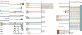
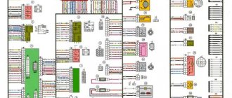
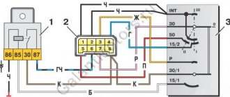
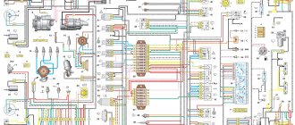
Electrical diagram of VAZ-2115-01
Years of production 2115: 1997—2012. This is a circuit with a regular button for rear fog lights (with locking), a fluorescent interior light, a connector for the clock and an 8-pin connector for the injector wiring.
1 — block headlights; 2 — fog lights; 3 — air temperature sensor; 4 - generator; 5 — electric motor of the engine cooling system fan; 6 — fan motor activation sensor; 7 — engine compartment lamp switch; 8 — block for connection to a single-wire type audio signal; 9 — sound signal; 10 — oil level sensor; 11 — front brake pad wear sensors; 12 — washer fluid level sensor; 13 — spark plugs; 14 — ignition distributor sensor; 15 - switch; 16 — carburetor solenoid valve control unit; 17 — carburetor solenoid valve; 18 — carburetor limit switch; 19 — speed sensor; 20 - starter; 21 - battery; 22 — relay for turning on fog lights; 23 — coolant level sensor; 24 — brake fluid level sensor; 25 — reverse light switch; 26 — coolant temperature indicator sensor; 27 — engine compartment lamp; 28 — windshield wiper gearmotor; 29 — oil pressure warning lamp sensor; 30 — block for connecting to the rear window washer electric motor; 31 — electric motor for windshield washer; 32 — ignition coil; 33 — instrument cluster; 34 — mounting block; 35 — brake light switch; 36 — blocks connected to the injection system wiring harness; 37 — ignition switch unloading relay; 38 — ignition switch; 39 — glove box lighting lamp; 40 — switch for the glove compartment lighting lamp; 41 — rear window heating switch; 42 — fog light switch; 43 — fog light switch; 44 — external lighting switch; 45 — alarm switch; 46 — steering column switch; 47 — instrument lighting regulator; 48 — hydraulic corrector scale illumination lamp; 49 — socket for a portable lamp; 50 — side direction indicators; 51 — switches in the front door pillars; 52 — lamp for individual interior lighting; 53 — electric heater fan; 54 — additional resistor of the electric heater fan; 55 — heater electric fan switch; 56 — backlight lamp for the electric heater fan switch; 57 — backlight lamp for heater control levers; 58 — display unit of the on-board control system; 59 — trip computer; 60 — switches in the rear door pillars; 61 — block for connection to the clock; 62 — electric fuel pump with fuel level sensor; 63 — ashtray lighting lamp; 64 — cigarette lighter; 65 — trunk lighting; 66 — trunk light switch; 67 — interior lamp; 68 — parking brake warning lamp switch; 69 — external rear lights; 70 — internal rear lights; 71 — plugs for connecting to the rear window heating element; 72 — license plate lights; 73 - additional brake signal.
See the complete diagram in one file below (click to enlarge):
Circuit 2115 with “high” panel 21083 is similar to circuit 21099 (except for the rear harness).
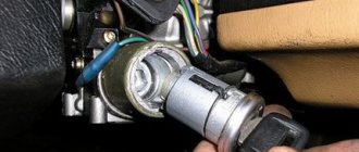
Removing the ignition switch
Disconnect the negative cable from the battery.
Remove the steering column covers.
1. Mark the wires suitable for the contact part of the ignition switch...
2. ...and disconnect them.
3. Using a slotted screwdriver, unscrew one screw securing the ignition switch to the steering column bracket on the left and the second, located below, to the right of the first.
4. With the ignition switch key in position “0” (“off”), use a slotted screwdriver with a narrow blade to push the ignition switch lock through the hole in the side wall of the steering column bracket.
5. Pull it towards you and remove the ignition switch.
6. To replace the contact part of the ignition switch, pry it with a screwdriver and remove the retaining ring.
The retaining ring may come off.
7. Remove the contact part of the ignition switch.
8. When installing a new contact part, turn its rotating part counterclockwise with a slotted screwdriver until it stops.
We remove the key from the ignition switch and insert the contact part into the housing so that the wide protrusion of the contact part coincides with the wide cavity of the housing.
We assemble the ignition switch in the reverse order.
9. To facilitate installation of the retaining ring, use pliers to bend the tendril
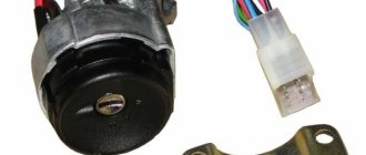
The structure of a car ignition switch
- Locking rod
- Frame
- Roller
- Contact disc
- Contact sleeve
- Block
- Protrusion of the contact part.
The lock mechanism is connected to many wires. They continue from the battery, connecting all the electrical devices of the car into a single chain. When you turn the ignition key, the electrical circuit is closed from the “-” terminal of the battery to the ignition coil. As a result, the current passes through the wires to the ignition switch, through its contacts it is directed to the induction coil, after which it returns back to the “+” terminal. As electricity passes through the coil, it generates high voltage, which it transmits to the spark plug. Therefore, the key closes the contacts of the ignition circuit, thereby starting the car engine.
Ignition system on Niva: self-replacement and ignition adjustment
As you know, engine performance is largely determined by the state of operation of the ignition system. Problems in the functioning of the latter can lead to the motor starting to work intermittently. From this material you can learn how to remove the ignition switch on a Niva with your own hands and adjust it, as well as what needs to be taken into account during this process.
Chevrolet Niva hub - replacement
To replace the wheel bearing in the field, you need to pull out the hub. This is carried out according to the following plan.
1. Dismounting the conical bushing.
2. Unlocking the nuts. The problem may lie in the fact that they often lick off or turn sour. In this case, you can use a chisel and a light hammer.
3. Use the nineteenth socket or wrench to remove the lever clamps. They are located both front and back.
4. The locking plates are removed. These are metal perforated strips that are often overlooked.
5. The seventeenth and tenth keys require removing the circuit pipes.
6. A stop is installed under the lever. Using two twelfths keys, unscrew the nut fixed on the upper arm retainer bolt.
7. The lower block is also unscrewed in the same way.
8. When there are no fasteners left, it is possible to pull out the entire system at once.
9. By fixing the steering knuckle with a clamp, you can knock out the hub.
10. After this, the screws securing the knuckle to the lever mechanism are removed.
Knowing the structure of the front wheel hub of Niva 21213, you can carry out repairs yourself, without contacting a service center.
Ignition switch and features of its replacement
Before removing the ignition module on a VAZ 21213 carburetor or injector, it is necessary to diagnose the ignition coil, distributor and spark plugs. As practice shows, spark plugs are often the cause of incorrect operation of the internal combustion engine. If you are sure that the problem lies in the fault, then the installed device will need to be changed.
How to replace the Niva ignition switch:
- First, the battery is disconnected and the steering column is removed.
- You need to mark the wires that are connected to the contact part of the VAZ ignition switch and disconnect them. Using a flat-head screwdriver, remove the bolt securing the system switch to the steering column bracket. You will also need to unscrew the screw that is located below, on the right side of the first one.
- Next, on Niva 21213 you need to turn the key to position 0, after which you need to use a screwdriver to slightly recess the device lock through the hole. The hole itself is located on the side of the steering column. Do not touch the exposed key.
- Before removing the ignition switch on the Niva, you need to pull it slightly towards you, after which the device is dismantled. In accordance with the connection diagram, the contact part of the device is replaced; to do this, you need to pry it off with a screwdriver and remove the retaining ring.
- Next, the contact part of the assembly is removed and changed if necessary. During installation, the rotating part must be turned counterclockwise using a screwdriver. Remove the key from the structure and install the contact part so that its wide protrusion can coincide with the wide cavity of the housing. Further assembly of the unit is carried out in reverse order.
Contactless (electronic) ignition of VAZ 2101. Scheme. Installation procedure
Replacing the ignition switch on a VAZ 2114 and wiring diagram
Since more and more owners of VAZ 2101 and “classics” are replacing the old ignition system with a contactless (electronic) one, it would not be amiss to talk about it.
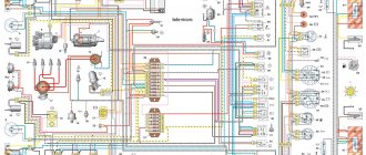
Scheme of the VAZ contactless ignition system
Explanation of the scheme:
- Non-contact sensor.
- Ignition distributor sensor.
- Spark plug.
- Switch.
- Ignition coil.
- Mounting block.
- Ignition relay.
- Ignition switch.
The following equipment will be required:
- Switch. Recommended models: K563.3734, K562.3734. The device includes 2 parts: the main unit and an additional one. Additional - serves as a reserve and can take over the tasks of the main unit or Hall sensor in the event of component failure.
- Candles (it is better to use A17 DVR or any similar option).
- Ignition coil marking 27.3705 (magnetic conductor must be open).
- Ignition distribution sensor (marking distributor 38.3706).
- Wire harness.
- High-voltage silicone wires (recommended manufacturers - TESLA or CEZAR).
You will need a set of tools:
- keys for spark plugs, 8, 10, 12, 13 millimeters;
- probe 0.7-0.8 millimeters;
- drilling equipment;
- strobe
Ignition installation steps:
Replace the original spark plugs with a new one (the gap should be set to 0.7-0.8 millimeters). Install the switch. The optimal location of the VAZ 2101 is the inner side wall of the compartment. For installation, you will need to drill 2 holes and screw the device to the splash guard with the emergency switch facing up. It is necessary that the switch radiator has a large contact area with the surface of the body (this will increase thermal output). The switch can also be fixed with self-tapping screws. Remove the distributor cap and start turning the crankshaft until the slider turns towards the first cylinder on the distributor
It is worth paying attention that the mark on the crankshaft pulley and the middle mark on the gas distribution system cover must match. Using the key “13” you need to unscrew the distributor and remove it
Take a new distributor and remove the cap from it. Then, turning the rod, scroll it until the slider turns in the direction of the 1st cylinder (as it was on the original distributor). Install a new distributor and tighten the nut to thirteen. Next, scrolling it in a circle, relative to its axis, position it so that the central point of the Hall device coincides with the edge of the beginning of the window cutout in the screen. Then, you can tighten the nut securing the distributor to the end. Replace the ignition coil. The procedure includes the following steps: unscrew the old coil (in this case, the conductors do not need to be removed from its terminals); replace with a new part; the wiring harness is connected using connectors to the switch and ignition distribution device; the black conductor is connected to ground (the terminal must have a tight connection to the car body); the red conductor is connected to terminal “K” on a new copy of the part; the brown wire from the tachometer (disconnected from the previous part) is also connected to “K”; The blue wire and the black-blue wire (disconnected from the previous part) are connected to terminal “B”. It must be taken into account that components “K” and “B” cannot always be placed symmetrically.
Put on the distributor cap and high-voltage conductors. Check each fastener and you can try to start the car.
If you can't start, the problem may be the following:
- A non-working switch has been installed.
- The problem is in the coil.
- Defect in the Hall sensor.
- There is a break in the wiring harness, or they are badly tangled.
- The distributor is not placed correctly.
- The ignition has failed.
- High-voltage conductors are tangled.
- An error was made when installing the conductors on the coil.
- The defect is located in the spark plugs or the gap is incorrectly set.
How to check the ignition module?
After installing and connecting all components, you need to diagnose the functionality of the module:
- First, the resistance between the terminals of the secondary winding is measured - the probes are connected to cylinders 1 and 4, and then to 2 and 3. The indicators can be any, the main thing is that they more or less coincide. A malfunction of the secondary winding will be indicated by an error in the indicators of more than 100 Ohms.
- After this, you need to test the wiring; to do this, you need to disconnect the block from the unit and set the multimeter to voltmeter mode, with one tester probe connected to pin A, and the second to ground. Start the engine and watch the tester display - the readings should be about 12 volts, the second contact is diagnosed in the same way.
- If there is no voltage, you should diagnose the safety element located in the mounting block under the center console. The reason for the lack of voltage can be not only a blown fuse, but also poor contact, broken wiring, as well as corrosion (author - AutoElectrika Diary channel).
Checking the quality of the ignition switch installation
It is logical that errors are possible when connecting contacts or incorrect installation of the lock itself. Therefore, it is necessary to test the protection in the installed state. You will need an ohmmeter and a voltmeter. Performance diagnostics:
- Checking the resistance between the terminals of the secondary winding: connect the probes to cylinders 1 and 4, then to cylinders 2 and 3. The data should approximately match. An error greater than 100 ohms indicates damage to the secondary winding.
- The wiring is checked with a voltmeter. The first control - one probe is placed on contact A, the second - on ground. Start the engine and record the data. Turn off the car and repeat the procedure with contact B. The readings should be about 12 volts.
- In addition, if there is no voltage, check the fuse, the possibility of broken wiring or corrosion of the contacts.
The last case is especially unpleasant, since you will have to check almost all the wiring, contact elements, etc. If there are possible suspicions about the electrical network, it is better to take the car to a professional auto electrician. Repairing it requires a thorough knowledge of the circuit and experience in finding defects.
Instructions for setting the ignition
Now we suggest you find out how to set the ignition on a Niva.
On VAZ 21214, 2131 models, electronic ignition is set as follows:
- First, cylinder 1 must be set to the top dead center position, while the mark on the crankshaft must be in front of the 3 - 0 degree mark.
- Then, to set it up, you need to dismantle the distributor cover and see where the slider is located - it should be directed towards the pin of cylinder 1. Using a strobe, you need to set the torque, after which the ground of the device is connected to the battery negative, and the positive terminal to the positive.
- Next, the regulator clamp should be connected to the high-voltage cable on cylinder 1 and marked with a mark on the crankshaft pulley. The engine starts, and its revolutions should be no more than 800 per minute, and the light from the strobe should be directed to the mark on the pulley. If the ignition adjustment was carried out correctly, the mark should coincide with the middle mark on the engine cover. If this is not the case, then the power unit must be turned off, then loosen the distributor fastening either clockwise or counterclockwise. The distributor cover is being dismantled; you need to ensure that the stator petals are aligned with the rotor mark.
- Next, the engine starts again and warms up to 80 degrees. Accelerate to 60 km/h and press the gas pedal sharply. If the module is inserted correctly, the engine may briefly detonate at this point.
Signs that it’s time to change the ignition switch
Early signs of a malfunction in the Chevrolet Niva ignition switch usually manifest themselves in the key jamming when it is turned in the cell. Slight jamming is especially common when turning the key from the “Ignition” position to the “Starter” position. Over time, the malfunction progresses and can lead to the key jamming in the cylinder.
At first, this problem can be solved by disassembling the lock and dripping oil into the cylinder, thereby reducing friction in it when turning the key. However, if the jamming progresses, then it is better to replace the lock before its cell jams tightly.
The presence of problems with the ignition switch is also indicated by the key slipping in the cylinder when it cannot be turned to the “Ignition” or “Starter” position. This situation also indicates a breakdown of the larva.
The second group of faults is related to the contact group. The Chevrolet Niva ignition switch is powered by several groups of energy consumers:
- in position “0” the car’s side lights can be turned on;
- in position “1” (“Ignition”) the high and low beams, turn signals and tail lights, the fuel pump, power windows, wipers, etc. work;
- in position “2” the starter starts.
In the case when several energy consumers, seemingly unrelated to each other at first glance, stop working, the problem may lie in a break, breakdown, or oxidation of the contact.
Such a malfunction does not necessarily require replacing the lock - you can repair the contact group by replacing damaged contacts. However, a problem with the contact group may indicate general wear and tear of the lock, so it is better to replace it entirely.
Niva ignition switch pinout
| Key position in the lock | Live contacts | Consumers to which voltage is applied |
| III (Parking mode) | 30 – INT 30/1 | — |
| I (Ignition on) | 30/1 — 15 | Generator excitation, lighting, wipers, internal combustion engine control (fuel pump, etc.), trunk lid heating, heater, turn, reverse lighting |
| II (Starter) | 30/1 – 15 30 — 50 | Turning on the starter |
Replacing the ignition switch VAZ-21213, VAZ-21214
To turn the car's electrical circuits on and off, use the ignition switch or simply the ignition switch. A mechanical anti-theft device is installed in the ignition switch, blocking the steering wheel rotation. The anti-theft locking rod extends when the key is placed in the “parking” position and removed from the lock. After this, turn the steering wheel so that the rod fits into the groove on the steering shaft, locking it.
The locking rod is recessed, releasing the shaft, when the key is turned from the “parking” position to the “off” position. The closure of the ignition switch contacts at various key positions and the switched circuits are shown in the table. The power supply circuits for the horn, brake light, hazard lights, cigarette lighter, lamp, plug socket for a portable lamp and high beam headlights are always turned on (regardless of the position of the key in the ignition switch).
Closing the ignition switch contacts
Live contacts
Generator excitation winding. Ignition system*.
Outdoor Lighting. Instrument lighting. Low and high beam headlights.
Fog light. Windshield and tailgate glass cleaners.
Carburetor solenoid valve control unit*.
Engine management system
(including electric fuel pump and engine cooling system fans)**.
Heated tailgate glass. Washer. Heater fan.
Direction indicators. Reversing light. Control devices.
*Only for VAZ-21213 engine.
**Only for VAZ-21214 engine.
Removing the ignition switch
Disconnect the negative cable from the battery.
Remove the steering column covers.
1. Mark the wires suitable for the contact part of the ignition switch...
2. ...and disconnect them.
3. Using a slotted screwdriver, unscrew one screw securing the ignition switch to the steering column bracket on the left and the second, located below, to the right of the first.
4. With the ignition switch key in position “0” (“off”), use a slotted screwdriver with a narrow blade to push the ignition switch lock through the hole in the side wall of the steering column bracket.
5. Pull it towards you and remove the ignition switch.
6. To replace the contact part of the ignition switch, pry it with a screwdriver and remove the retaining ring. The retaining ring may come off.
7. Remove the contact part of the ignition switch.
8. When installing a new contact part, turn its rotating part counterclockwise with a slotted screwdriver until it stops. We remove the key from the ignition switch and insert the contact part into the housing so that the wide protrusion of the contact part coincides with the wide cavity of the housing.
We assemble the ignition switch in the reverse order.
9. To facilitate installation of the retaining ring, use pliers to bend the tendril.
Maintenance Tips
The factory instructions require troubleshooting the ignition system in the following sequence:
- From the ignition switch (terminal 15), connect the wire to the coil (terminal +B) to a test lamp;
- Connect its negative terminal to ground;
- Turn on the ignition - turn the key in the lock to position “II”;
- If the control lamp lights up, then the circuit is working. If not, look for damage to the wire;
- With the ignition on, pull out the central wire from the coil from the distributor;
- Bring its metal tip to the cylinder block so that a gap of 3-4 mm forms between them;
- Turn on the starter for a few seconds;
- If the spark jumps, the coil is working.
We change the Shnivy ignition switch. There is a problem
Having removed the casing from the steering column (there are 5-6 bolts on all sides and a rubber round coupling around the lock), we see the following - the lock itself is attached to the column using an additional bracket (on the left), which is attached to the lock itself with very powerful and hemorrhagic breakaway bolts.
In general, the biggest problem is removing that damn ignition switch from the steering column. It is secured with 4 breakaway bolts, which are specifically designed to make it more difficult to steal a car.
Therefore, if you are not going to repair the lock itself, but simply decided to replace it, then do not forget to buy 4 tear-off bolts!
That is, they are easy to tighten; the caps have hexagonal key heads, which, at a certain tightening torque, break and a round cap remains. This is what we will need to unscrew, as many as 4 pieces. It turns out that putting it on is easy, but taking it off is difficult.
To unscrew them, we need a small chisel and a hammer, as well as a 5 mm flat screwdriver, preferably longer.
We unscrew it COUNTER-clockwise, adjust the chisel so that the angle of inclination is sharper, so that the force of the blow goes sideways, and not directly into the head. And we try to make a notch on the head of the breakaway bolt with a chisel; the most important thing here is to remove the bolt from the thread so that, once stuck, it begins to move.
Thus, moving the chisel, punching 3-4 mm at a time, we turn the bolt to the left until it loosens. Then you can unscrew it with your fingers or pliers if it still doesn’t turn well.
This is what such a bolt looks like, it goes to the cone. Let's take on the second one.
The most difficult one will be the one on the upper right; it will be very difficult to climb there.
Having unscrewed the bolts, you have practically won, now you can replace the lock itself without any problems, everything is quite simple, you disconnect 4 wires - red, blue, pink and black. True, you will also have to unscrew the lock itself from the second part of the fastening - using a Phillips screwdriver, 3 bolts.
Repair instructions
The location of the 3Z is known to everyone; this unit is located directly under the steering wheel. To properly replace or repair a device, you must follow the instructions:
First, disconnect the battery and remove the plastic steering column cover, which is secured with bolts. Next, press out the fastening and disconnect the connector with the 33 wiring from the control panel wiring block. When unplugging, be careful not to damage the plug. Having done this, you will also need to disconnect the plug with the 3Z wires from the connector with the wiring of the immobilizer control system. Using a hammer and chisel or a drill, you need to remove the four breakaway screws and remove the assembly from the steering column. You can't just unscrew these bolts. VAZ engineers decided to use this method of installing the protection in order to protect car owners from possible thefts. This method of fastening, as you can guess, makes it very difficult to dismantle the protection, so at this stage you will have to tinker. In any case, the bolts can be dismantled or drilled out, but instead you will have to purchase new ones in advance. After completing these steps, you can bend the connector mount with wiring from the 3Z. The terminals with wires are removed from this connector. Next, you need to compress the latches again and dismantle the plastic cover of the device itself. If you plan to simply change the node, then this can be done at this stage. We suggest that you familiarize yourself with more detailed information on repairs; it is quite possible that simple steps will restore the unit’s functionality and save money. So, if you decide to repair the mechanism, then at this stage you need to press out two more plastic clips and remove the contact group from the cover. Next, it is necessary to carry out a thorough visual diagnosis of the contacts. If you notice that the contacts have oxidized or burnt, you can restore their functionality by cleaning them using fine-grained sandpaper. Get rid of oxidation and plaque, but do not go too hard so that the contacts do not wear off. If the damage to the contacts is too severe, then cleaning will not solve the problem; you will only need to change either the contactor itself or only the contact group. If everything worked out with the contacts, then you can assemble and install the 3Z
During assembly, pay attention to the position of the terminals with the wiring in the connector; under no circumstances should they be mixed up. After completing these steps, install the locking device back into place, while pre-sinking the locking rod of the anti-theft unit. To do this correctly, install the key in the 3Z and turn it to any position, the main thing is that it is not in the “0” position
If the key is replaced, then the transponders, these are special electronic code components on the head of the key, also need to be changed.
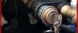
Lock
I worked successfully for 14 years, after which I apparently decided it was time to retire.
Ignition switch for Niva
Changing the ignition switch
at the cornfield. we face the marriage and get out of the situation.
If you do not do this, then you will also have to carry out the training procedure, as well as change the lock cylinder on the trunk and doors, and this is a rather labor-intensive process. Otherwise, you will have to use the old key to open the doors and trunk, and the new one. Agree, this is completely inconvenient, but this is only relevant for those car owners who have changed their license plate.
We change the Shnivy ignition switch. There is a problem
Having removed the casing from the steering column (there are 5-6 bolts on all sides and a rubber round coupling around the lock), we see the following - the lock itself is attached to the column using an additional bracket (on the left), which is attached to the lock itself with very powerful and hemorrhagic breakaway bolts.
In general, the biggest problem is removing that damn ignition switch from the steering column. It is secured with 4 breakaway bolts, which are specifically designed to make it more difficult to steal a car.
That is, they are easy to tighten; the caps have hexagonal key heads, which, at a certain tightening torque, break and a round cap remains. This is what we will need to unscrew, as many as 4 pieces. It turns out that putting it on is easy, but taking it off is difficult.
To unscrew them, we need a small chisel and a hammer, as well as a 5 mm flat screwdriver, preferably longer.
We unscrew it COUNTER-clockwise, adjust the chisel so that the angle of inclination is sharper, so that the force of the blow goes sideways, and not directly into the head. And we try to make a notch on the head of the breakaway bolt with a chisel; the most important thing here is to remove the bolt from the thread so that, once stuck, it begins to move.
Thus, moving the chisel, punching 3-4 mm at a time, we turn the bolt to the left until it loosens. Then you can unscrew it with your fingers or pliers if it still doesn’t turn well.
This is what such a bolt looks like, it goes to the cone. Let's take on the second one.
The most difficult one will be the one on the upper right; it will be very difficult to climb there.
Having unscrewed the bolts, you have practically won, now you can replace the lock itself without any problems, everything is quite simple, you disconnect 4 wires - red, blue, pink and black. True, you will also have to unscrew the lock itself from the second part of the fastening - using a Phillips screwdriver, 3 bolts.
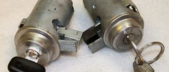
Inspection of the larva
A lock without a key looks like this - stoppers stick out in all directions, which catch when turning and thus prevent the cylinder from turning inside.
When you insert the key into the cylinder, all the pins should be removed, thus they will not interfere with the key turning. In our case, we had 1 pin sticking out on the left, which clung and did not allow the “larva” to spin. We worked on it with a file.
Also carefully inspect the lock cylinder; it is quite possible that you will see burrs and even grooves on the upper side that were “trodden down” by the pressure pin running along its top. It turned out that for all the time (and the car is already 10 years old), he made his own move in the “body of the larva” (outer side), which ended in a dead end. And in this position the key was locked (position I - ignition).
There, they also used a needle file to grind off the furrow it made; make the angle as sharp as possible. It is very difficult to explain, so think about how and what should work. The lock cylinder is made of soft material and in 10 years it will definitely wear out, the rear round pin “drills” its path. Point it the right way and you won't have to buy a new ignition switch.
On sale you can find locks with cylinders (3 pieces - for the front doors and trunk) - the cost is approximately 1,300 rubles.
Or take it without the cylinders - it costs 900 rubles, but now you will have 2 keys - one to start the car, and the second to close/open the front doors and trunk. So repairing the lock is a very good option, you win in 2 categories at once - you save money, and you will still have 1 key for everything, as before.