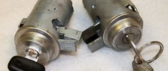
To turn the car's electrical circuits on and off, use the ignition switch or simply the ignition switch.
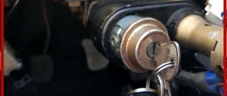
A mechanical anti-theft device is installed in the ignition switch, blocking the steering wheel rotation.
The anti-theft locking rod extends when the key is placed in the “parking” position and removed from the lock.
After this, turn the steering wheel so that the rod fits into the groove on the steering shaft, locking it.
The locking rod is recessed, releasing the shaft, when the key is turned from the “parking” position to the “off” position.
The closure of the ignition switch contacts at various key positions and the switched circuits are shown in the table.
The power supply circuits for the horn, brake light, hazard lights, cigarette lighter, lamp, plug socket for a portable lamp and high beam headlights are always turned on (regardless of the position of the key in the ignition switch).
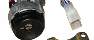
Removing the ignition switch
Disconnect the negative cable from the battery.
We mark the wires suitable for the contact part of the ignition switch...
...and disconnect them.
Using a slotted screwdriver, unscrew one screw securing the ignition switch to the steering column bracket on the left and the second, located below, to the right of the first.
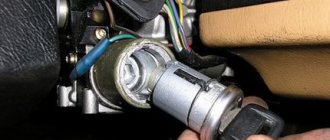
With the ignition switch key in position “0” (“off”), use a slotted screwdriver with a narrow blade to push the ignition switch lock through the hole in the side wall of the steering column bracket.
Pull it towards you and remove the ignition switch.
To replace the contact part of the ignition switch, pry it with a screwdriver and remove the retaining ring.
The retaining ring may come off.
We take out the contact part of the ignition switch.
When installing a new contact part, turn its rotating part counterclockwise with a slotted screwdriver until it stops.
We remove the key from the ignition switch and insert the contact part into the housing so that the wide protrusion of the contact part coincides with the wide cavity of the housing.
We assemble the ignition switch in the reverse order.
To make it easier to install the retaining ring, use pliers to bend the tendril
Replacing the ignition switch Niva VAZ 21213, 21214, 2131 lada 4×4
We remove the ignition switch to replace the assembly or its contact group.
Disconnect the negative cable from the battery.
Remove the steering column covers (see here).
Disconnect the wiring harness connector from the ignition switch.
Note. On cars manufactured before 2009, the wires to the ignition switch are connected without a common block (photo below), so before disconnecting them, we mark the wires suitable for the contact part.
...and disconnect them.
Using a slotted screwdriver, unscrew one screw securing the ignition switch to the steering column bracket on the left...
...and the second one, located below, to the right of the first.
By placing the ignition switch key in position “0” (“off”),...
... using a slotted screwdriver with a narrow blade, we recess the ignition switch lock through the hole in the side wall of the steering column bracket.
Pull it towards you and remove the ignition switch.
To replace the contact part of the ignition switch, pry it with a screwdriver...
...and remove the retaining ring.
The retaining ring may come off.
We take out the contact part of the ignition switch.
When installing a new contact part...
...turn its rotating part counterclockwise with a slotted screwdriver until it stops.
We remove the key from the ignition switch and insert the contact part into the housing so that the wide protrusion of the contact part coincides with the wide cavity of the housing.
. terminals “15” and “30” should be located opposite the locking rod of the switch.
We assemble the ignition switch in the reverse order.
Reinstall the retaining ring of the contact group.
To make it easier to install the retaining ring, use pliers to bend the tendril.
Before installing the switch, insert the key into it and turn the key to the “O” position.
Install the ignition switch in the reverse order.
Lada 2106 1.6i Selesta › Logbook › Installation of the ignition switch 2110 and steering column Kalina/Chevy-Niva
At the request of the workers, I present the manual!
=) I’ll immediately explain one thing, I did it a little away from the manuals that are on the net, because... I don’t have a casing from Kalina yet and I didn’t install the sawed-off part from my original switches. I also have a steering wheel with a reach that I had to “dance” under.
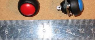
— Steering column switches assembled 1118/2123 (Kalina/Chevy-Niva) — 20 female terminals — Insulating tape (heat shrink) — Ignition switch 2110 with key illumination — Screws 4 pcs. for attaching the lock - 3-position lighting key from 2108-09, Niva, or similar, then: 1st position - lighting off, 2nd position - dimensions, 3rd position - low. Just in case, you need a supply of fuses.
So, let's start with the ignition switch. We remove the steering column cover, take out the contact group of the original lock.
We remove the wires from the terminals and switch them by color to the block of the new lock. Wire colors match
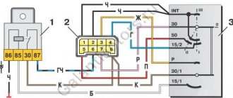
Ignition switch pinout
- Black with black - Red with red - Blue with black-blue (double) - Pink with pink The brown
wire
remains free Thin black and white wires go to the key illumination, power it as you prefer
We take out the old key and disconnect the wires from the chip, switch the wires to our new key:
Key pinout
- 30 - black wire - 56 - green - 58 - black and white - X - to the ignition (to the same brown wire that was left hanging not connected to the ignition switch)
We hang the ignition switch on the steering shaft at the very bottom and tighten the screws .
That's it, the lock is installed, nothing burned out))) the car starts, we switch to the steering column.
We climb behind the dashboard and disconnect 3 chips of the steering column switches, removing the wires from there.
We remove our “helicopter” and take the wire cutters, biting off all the wires at the root. Now you need to strip each wire, crimp the terminals and insulate them.
Now let's move on to the case that I wrote at the beginning - I went my own way. I looked at how it was done in other manuals and did not understand how to attach the new switches. They put some kind of tins there, I didn’t like it. And I also sawed off, as they say, from the original switches a section on which there is a clamp and a screw holding the casing.
While I was sawing it off, it burst. And when I moved it this way and that on the shaft, I again didn’t understand the meaning of how it held up. If the photos were normal, I would have caught up. And I decided that I would not bet.
Then let's do it! We take a key of 10 and loosen the clamp holding the so-called “binoculars”.
You should have already removed the old ignition switch. We pull it out to the length we need, twisting it with the collar (the one on the white plastic thing) up and placing it in the center. Now the block of the new steering columns becomes like the original one.
We take the steering wheel and make holes in it for the clamps of the round release switch, which rotates on the steering column block, which is also the contact ring for the signal. It was easier for me; I sawed holes not in metal, but in a round plastic plate of the steering adapter.
We put on the steering wheel, in my case the adapter, and make sure that the clamps fit into the holes made (in my photo they are not fully seated). Now you can put on the steering wheel, tighten the nut slightly and adjust the steering column switch block by moving it along the “binoculars”, and the “binoculars” in turn moving along the steering shaft. Once everything is correctly in place, you can tighten the clamps on the block and on the “binoculars”.
Well, all that remains is to connect the wires according to the pinout. This picture is taken from the online manual I used to make it. The diagram is convenient and correct.
Pinout of steering column switches
After connecting the wires, do not forget to put the gray-black wire on the signal contact in the block on the back side
and run the wire to the steering signal from the contact on one of the clamps.
Source
How to replace the ignition switch of a VAZ-2121 car
To turn the car's electrical circuits on and off, use the ignition switch or simply the ignition switch. A mechanical anti-theft device is installed in the ignition switch, blocking the steering wheel rotation. The anti-theft locking rod extends when the key is placed in the “parking” position and removed from the lock. After this, turn the steering wheel so that the rod fits into the groove on the steering shaft, locking it.
The locking rod is recessed, releasing the shaft, when the key is turned from the “parking” position to the “off” position. The closure of the ignition switch contacts at various key positions and the switched circuits are shown in the table. The power supply circuits for the horn, brake light, hazard lights, cigarette lighter, lamp, plug socket for a portable lamp and high beam headlights are always turned on (regardless of the position of the key in the ignition switch).
Closing the ignition switch contacts
Live contacts
Generator excitation winding. Ignition system*.
Outdoor Lighting. Instrument lighting. Low and high beam headlights.
Fog light. Windshield and tailgate glass cleaners.
Carburetor solenoid valve control unit*.
Engine management system
(including electric fuel pump and engine cooling system fans)**.
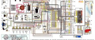
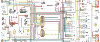
Wiring diagram Niva 21214
Cars considered Niva 21214 injector.
All electrical diagrams for the VAZ 21214 Niva are in excellent quality. To enlarge the electrical diagram, click on it, then click on the cross in the lower right corner of the image.
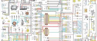
Front wiring harness connection diagram
1 — right front lamp; 2 — right side turn signal; 3 — connection block with the wiring harness of the right lamp and side direction indicator; 4 — right headlight; 5 — connection block with the wiring harness of the right headlight; 6 - starter; 7 - battery; 8 - generator; 9 — left headlight; 10 — connection block with the left headlight wiring harness; 11 — left front sidelight; 12 — left side direction indicator; 13 — connection block with the wiring harness of the right front lamp; 14 — sound signal; 15 — outside air temperature sensor; 16 — windshield wiper; 17 — coolant temperature sensor for the instrument cluster; 18 — sensor for emergency oil pressure warning lamp; 19 — windshield washer; 20 — brake fluid level warning lamp sensor; 21 — starter blocking relay; 22 — connection block with instrument panel harness
Electrical diagram of the Niva 21214 engine control system.
A - place of transition of the wiring harness from the engine compartment to the passenger compartment; 1 — adsorber purge valve; 2 — throttle assembly; 3 — coolant temperature sensor; 4 — right cooling fan; 5 — left cooling system fan; 6 — ignition coil; 7 — spark plugs; 8 — mass air flow sensor; 9 — crankshaft position sensor; 10 — connection block with the wiring harness of the control oxygen concentration sensor; 11 — control oxygen concentration sensor; 12 - phase sensor; 13 — knock sensor; 14 — connection block with the injector wiring harness; 15 — nozzles; 16 — gas pedal; 17 — connection block with the instrument panel wiring harness; 18 - main relay; 19 — right cooling fan relay; 20 — left cooling fan relay; 21 — fuel pump relay; 22 — fuel pump fuse; 23 — connection block with the rear wiring harness (to the fuel module); 24 — diagnostic block; 25 — terminal for connecting the wiring harness to ground in the vehicle interior; 26 — fuse block of the engine control system; 27 — green connection block with the wiring harness of the APS status indicator (LED); 28 — black connection block with the wiring harness of the APS status indicator (communication coil); 29 — control unit of the automobile anti-theft system (ATS); 30 — connection block with the wiring harness of the diagnostic oxygen concentration sensor; 31 — diagnostic oxygen concentration sensor; 32 — electronic engine control unit (controller) “Bosch” ME17. 9.7
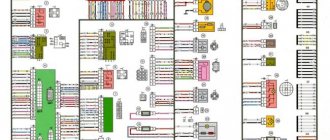
Instrument panel wiring harness connection diagram.
1 — connection block with the front wiring harness; 2 — connection block with the wiring harness of the engine control system; 3 — alarm switch; 4 — external lighting switch; 5 — turn relay; 6 — relay for turning on fog lamps in the rear lights; 7 — instrument cluster; 8 — switch for cleaner and washer of the luggage compartment door glass; 9 — heater switch; 10 — three-lever steering column switch; 11 — ignition switch; 12 — brake pedal position sensor and brake signal switch; 13 — clutch pedal position sensor; 14 — relay for heating the glass of the luggage compartment door; 15 — high beam relay; 16 — low beam relay; 17 — ignition relay; 18 — switch for heating the glass of the luggage compartment door; 19 — rear fog light switch; 20 — windshield wiper relay; 21 — backlight lamps for the heating and ventilation control unit; 22 — reverse light switch; 23 — differential lock activation sensor; 24 - additional fuse block; 25 — main fuse block; 26 — parking brake warning lamp switch; 27 — vehicle speed sensor; 28 — heater fan; 29 — additional heater resistor; 30 — cigarette lighter; 31 — control lamp block; 32 — indicator for turning on the heated glass of the luggage compartment door; 33 — differential lock activation indicator; 34 — instrument lighting regulator; 35 — connection block with rear wiring harness; 36 — connection block to the audio system
Electrical diagram Niva 21214.
Rear wiring harness connection diagram.
1 — connection block with the wiring harness of the engine control system; 2 — connection block with the instrument panel wiring harness; 3 — right interior lamp; 4 — limit switch of the right door; 5 — fuel module; 6 — limit switch of the left door; 7 — left interior lamp; 8 — tailgate glass cleaner; 9 — connection block with the wiring harness for the tailgate glass cleaner; 10 — license plate lights; 11 — element for heating the glass of the luggage compartment door; 13 — tailgate glass washer; 14 — rear right lamp; 15 — additional brake signal; 16 — rear left lamp
wire colors in the diagram.
| bl = blue | br = brown | el = cream | ge = yellow |
| gn = green | gr = gray | nf= neutral | og=orange |
| rs = pink | rt = red | sw = black | vi = purple |
| ws = white | hbl = blue | hgn= light green | rbr = magenta |
Tags:Wiring diagrams Niva 4×4
Ignition switch Niva Chevrolet – Niva Chevrolet (VAZ 2123, Chevy)
Ignition switch Niva Chevrolet – Niva Chevrolet (VAZ 2123, Chevy)
| Niva Chevrolet repair manual | spare parts catalog |
| Design Features |
| On VAZ-2123 vehicles, an ignition switch of type 2123–3704005 is used with an anti-theft locking device, a lock against re-starting the starter without first turning off the ignition, and a communication coil for the ignition key transponder with the automobile anti-theft system. |
| Figure 9.9. Ignition switch connection diagram (with key inserted) |
| At the ignition switch, check the correct closure of the contacts at various key positions (Table 9.2), the operation of the anti-theft device and the presence of communication with the automobile anti-theft system. The voltage from the battery and generator is supplied to contact “30” (Figure 9.9). |
| Table 9.2 Switched circuits for different key positions |
| Key position |
| Live contacts |
| Switched circuits |
| Engine management system, generator excitation, headlights, turn signal, control |
| instruments, windshield and rear window cleaners and washers, front door window lift motors |
| See position I |
| To unload the contacts of the ignition switch, a K6 relay is installed in the mounting block. |
| The anti-theft locking rod should extend when the key is turned to position 0 (off) and removed from the lock. The locking rod must be recessed after turning the key from position 0 (off) to position I (ignition). The key should only be removed from the lock in position 0. |
| The locking device against reactivation of the starter must not allow the key to be turned again from position I (ignition) to position II (starter). Such a rotation should only be possible after first returning the key to position 0 (off). |
| Removing and installing the ignition switch |
| 1. Remove the upper and lower steering column casings (see “Dashboard”). |
| 2. Disconnect the ignition switch wire block from the wiring harness. |
| 3. Disconnect the block with the ignition switch wires from the ignition relay. |
| 4. Using a chisel or screwdriver and hammer, remove or drill out four self-cutting bolts. Remove the switch from the steering column. |
| 5. Install the switch in the reverse order of removal, having previously pushed in the locking rod of the anti-theft device. To do this, insert the key into the switch and turn it from position “0”. |
Features of the modification
First of all, the changes affected the engine management system and control instruments. In particular:
- The wiring diagram for Niva 21213 received an additional wiring harness in the engine compartment for connecting a microcontroller and sensors;
- On the Niva model of recent years of production, a more advanced power unit with the VAZ-21214 index is installed. Instead of a carburetor, it has a fuel frame with injectors from GM. The price of a car with injection has increased because of this;
- The instrument panel has changed - the design is borrowed from the VAZ 2108 model.
Ignition system
The VAZ 21213 engine uses a non-contact ignition system consisting of:
- ignition distributor sensor (marking 3810.3706). It is responsible for creating control pulses supplied to the electronic switch;
- switch (model marking – 3620.3734) in climatic version U2.1 (corresponds to GOST 15150);
- ignition coils (marking 27.3705).
For reference: this device provides increased spark energy, which helps start the engine in cold weather, and also improves the performance of the power unit when operating the vehicle on low-quality fuel.
Dashboard
A modified instrument panel appeared on the car. In particular, instead of a voltmeter, the manufacturer installed a low battery discharge lamp (no. 12 in the diagram).
Tip: if you often operate your car in off-road conditions, you can buy and connect a voltmeter to the instrument panel yourself. It is more informative than a warning light and will allow you to identify electrical system faults long before the battery discharges.
Ignition switch 2110 for Niva
I installed the ignition switch from a VAZ 2110. I have not connected the microswitch yet, I only connected the backlight with the door open.
Due to the fact that the frame of the instrument panel is from a VAZ 21213, the Kalinovsky steering column casing did not fit on top. I had to cut the upper part of the casing in place and shape it with glass mat and polyester.
On the lower part of the casing at the bottom I built up the edges with plastic plates. So that less fucking would be visible.
I took it apart several times. So far I have chosen the optimal position of the steering column and ignition switch in relation to the casing and steering wheel.
Order code: 122326
Good day, dear readers.
The lock appears to be made with high quality, everything holds tightly, the key moves smoothly. I didn’t find any fastening bolts in the kit, either they weren’t there or I lost them, the order was large, there were a lot of items. In general, I purchased separately: Bolt M6x1.0x28 VAZ-2101,2109 ignition switch x 4 pcs.
There is nothing complicated about installation and connection. You don’t even have to remove the old lock, because... 2110 is hung on the right side.
There remains 1 unconnected wire, which is a constant “+”, previously it was responsible for turning on the lighting (dimensions and headlights). It can be directly connected to the light switch, but then if you forget to turn it off, you can drain the battery. This problem is solved by installing additional relays.
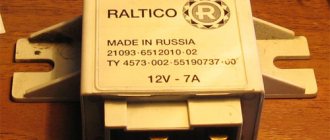
To be honest, I don’t know how the circuit along the starter line was implemented on 2110, but on 2106 there were shortcomings, due to the absence of a relay in the circuit, the entire load was borne by the contact group of the ignition switch, which could lead to frequent breakdowns of the ignition switch itself. So, in order to avoid such problems with the new lock, we install an additional 12V 4-pin AVAR electromagnetic relay. According to the scheme:
This lock also has LED lighting, I haven’t connected it yet, but I will do it later.
Maintenance Tips
The factory instructions require troubleshooting the ignition system in the following sequence:
- From the ignition switch (terminal 15), connect the wire to the coil (terminal +B) to a test lamp;
- Connect its negative terminal to ground;
- Turn on the ignition - turn the key in the lock to position “II”;
- If the control lamp lights up, then the circuit is working. If not, look for damage to the wire;
- With the ignition on, pull out the central wire from the coil from the distributor;
- Bring its metal tip to the cylinder block so that a gap of 3-4 mm forms between them;
- Turn on the starter for a few seconds;
- If the spark jumps, the coil is working.
Tip: you can quickly check the switch in one way - take it from a working car. If the car starts with the new switch, then you need to buy a new one.
conclusions
The modification of the VAZ 21213 Niva car undoubtedly benefited him. The new engine and improved ignition system have made its operation even easier and more confident in harsh conditions.
>
| Electrical equipmentFuses and relaysElectrical circuitsConnector diagramsEngine compartment wiringDashboard wiringWiring of the middle and rear partWiring of doors and tailgateRemoving the fuse boxGeneratorGenerator malfunctionsRemoving (replacing) the generatorRepairing the generatorStarterStarter malfunctionsRemoving (replacing) the starterRepairing the starterIgnition switchReplacing the ignition moduleReplacing spark plugsEngine management system Fault codesReplacing fuses and relays - engine management systemReplacing the controllerReplacing the crankshaft sensorReplacing the cooling sensor fluidReplacement of the throttle sensorReplacement of the MAF sensorReplacement of the knock sensorReplacement of the oxygen sensorReplacement of the speed sensorLighting and alarm breakdownsLighting diagramsWorking of the steering column switchRemoving the steering column switchAdjusting the headlightsTips for replacing lampsReplacing the headlight lampsReplacing the front turn signal lampReplacing the side turn signal lampReplacing the tail lamp lampsReplacing the fog light lampReplacing the license plate lamp Replacing the trunk light bulbReplacing interior light bulbsReplacing the lamp glove compartmentReplacement of block headlightReplacement of fog lightReplacement of side turn signalReplacement of rear lightReplacement of license plate lightReplacement of additional brake lightReplacement of interior lampsReplacement and adjustment of sound signalContact ring of sound signalWindow wipers (working diagrams)Window wiper malfunctionsReplacement of wiper relayRemoval (repair) of windshield wiperRemoval of rear windshield wiperWindshield washer Rear windshield washer Heater fan motor diagram Malfunctions of the heater fan motor Replacement of the heater fan motor Replacement additional heater fan resistor Diagram of the radiator fan electric motor Replacement of the radiator fan electric motor Instrument cluster Malfunctions of the instrument cluster Removing the instrument cluster Replacement of instrument cluster lamps Headlight adjustment and instrument backlight switches Removing the hazard warning button Replacement of the oil pressure sensor Replacement of the coolant temperature sensor Replacement of the reverse light switch Replacement of the brake light switch Replacement of the parking brake lamp switch Electric windows B Lock locator Rear window defroster Anti-theft. immobilizer systemImmobilizer trainingImmobilizer problems |