The Rezzo brothers inspired me to think about this topic. and Booroondook in particular. After he and I completed the fine-tuning of the hatch. (my theory, its implementation) He suggested thinking in this direction. After some time, a scheme was born.
Owners of non-sedans were always envious, owners of sedans, as they came from the store, opened one trunk with an alarm, leaving all the other doors under guard and calmly, without fearing anything, loaded countless packages from Auchan :). Now owners of cars in other bodies can do the same! To do this you need a couple of hours of free time, a few details. And skills in working with car electrical systems. So let's get started.
The scheme was implemented and tested on a Rezzo car. Executed by AlexIz If anyone takes up the implementation on a Lacetti or other car, please let me know so that the connection features can be included in the article.
Improvement of the central locking of Chevrolet Rezzo / Lacetti in hatchback and station wagon bodies. Development: Mitya. https://nsskn.narod.ru
Forum for questions and answers.
Implemented functions: 1. When the central locking is opened, the rear door lock does not open (if opening is necessary, install diode D3) 2. The rear door lock opens from an additional alarm channel. 3. When the door is opened, the lock is locked. And the next time the door slams, it becomes locked. They came from the store, opened the back door, rummaged around, slammed it, and the door was guarded again. 4. If the central locking is open, then the back door does not lock. The car is in nature, the doors are open, we go here and dig around. 5. When the central locking is closed, the door is locked.
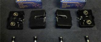
Required Components: Module
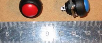
Central lock from VAZ 21093-6512010 at the end there may be different numbers -01 -02 and so on, but it seems that this is not important. The cost is around 200 rubles. The relay here is better not a powerful one, but a signal one, this one has a winding resistance of 960 Ohms. Current consumption is 12.5 milliamps. It will be energized as long as the door is open. Low-power diodes with a current of 1A. Button to open the fifth door, if needed. for example this one. AlexIz: The implementation uses a trunk opening button from ten. Lamp shut off switch in trunk if needed. For example this one. AlexIz: Improvements to the additional central locking unit. For ease of installation of the system as a whole, I decided to install an additional relay K1 and diodes D1 and D2 (see diagram) directly in the housing of the additional central locking unit and remove an additional connector from it. It turned out like this.
Block before and after modification
Improvements to the standard scheme
We disconnect the rear door motor (M5) from the standard central locking system and connect it to the module from the VAZ
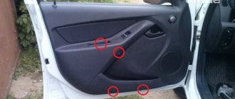
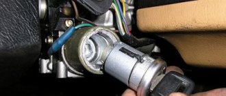
AlexIz: The motor and sensor are turned off at connector C401. It is located at the top behind the trim on the left side of the trunk. In order to get to it, you need to remove the entire trim on the left side of the trunk. It's actually not difficult. First, remove the plastic trunk sill. To do this, you need to unscrew two plastic screws, pull out the pistons and pull out (without fanaticism) the threshold upwards. It is simply secured with latches. After this, unscrew the two screws securing the side panel. They can be seen if you peel back (remove) the trunk carpet. Unscrew the seat belts with a 17mm wrench and carefully pull the trim towards the car axle. Be careful with the plastic joint in the area of the bottom of the rear seats. Ideally, the trim would have been removed there too, but it was too much for me. The sidewall is also on the clamps. Slowly everything will clear up. The upper part of the casing is secured from below with three self-tapping screws, and the rest is secured with latches. All. We reached C401.
I WARN! The photo shows only connector C401. Wires are not connected correctly. To connect, you need wires going up the harness!
VAZ 2109: central locking - purpose, operating principle, installation method
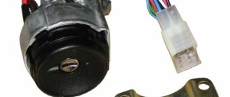
The central locking unit of the VAZ 2109 ensures the safety of the vehicle, which is one of the most important factors for the driver. There are different anti-theft security systems for car safety. An important role is played by installing door locks. The main purpose of the device is to simultaneously close and open doors in a car. In addition, on the VAZ 2109, central locks control the luggage compartment and fuel tank lids.Features of connecting the system to a lock with variable polarity
In this case, the car alarm must be connected directly to the car's power wires, which are again looked for with a probe. First, use it to find the negative power wire (the device should be connected to the positive, and then press the corresponding button on the alarm, determining the required wire). They look for another wire (power) in the same way.
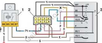
After this, you will need to cut the identified power wires, purchase two relays if we are talking about a car alarm with low-current type outputs, and connect according to the diagram below:
- general contacts - to the wires coming from the driver's doors;
- normally closed contacts - to those wires that go to the lock button or to the central locking unit;
- normally open contacts – to the “plus”.
You have successfully completed the procedure for connecting the alarm to the central locking!
Did you like the article? Follow our channel for new ideas of useful car tips. Subscribe to us in Yandex.Zen. Subscribe.
The problem of how to connect an alarm system to the central locking of a domestic car has been relevant for VAZ owners since 2000. Before this, central locks were not installed at all on Tolyatti models. Now the useful device is offered for basic configurations as an additional option. Realizing the benefits of central locking and car security alarms, many car owners install both devices on domestic cars of all years, especially since self-installation helps save money. VAZ models make up about half of the country's car fleet, and ensuring their safety is of interest to millions of drivers.
Theory
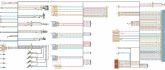
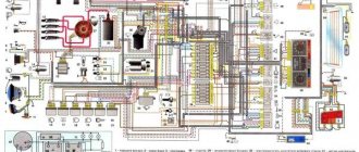
Before starting the installation, I want to warn you about the characteristics of my particular VAZ 2114 car (2006 model year, “Lux” equipment, the wiring under the dashboard is numbered as “VAZ 2115-...”), since I myself, from personal experience, have seen “four” and “tags” of the same year of manufacture, the same configuration, but with completely different wiring (I assume that this was due to different supplies of wiring to the conveyor).
After looking at the information on the Internet, I came to the conclusion that the overwhelming number of people install the control unit according to the incorrect diagram “D”, from the instructions, which will not fit the Samar family (VAZ 2108/09/99/13/14/15) , since the opening and closing of doors (or rather, the supply of a signal to the BUDU (Door Lock Control Unit)) in Samara is controlled by a “minus”, and according to the “D” scheme, control occurs by supplying a “plus” to the BUDU. As I found out, this scheme only works when the standard BUDU is removed and the BU works every other time and only one button on the control key works. In my case, when connecting circuit “D” (I tried to connect it together with the BUBD), I burned several fuses and started looking for another connection method.
TsBKE Lada Granta, Kalina, Priora: purpose, articles, pinout, errors
The central body electronics unit (CBEC) is designed to perform a number of vehicle functions. There are about 15 varieties of this block in total. We understand the features of the CBKE, study the connectors, the purpose of the contacts, fault codes, etc.
Turbomotor412 helped the Lada.Online website in collecting information.
Installing a central lock on a VAZ 2109 car
On the VAZ 2109, installation of the central lock is carried out in two stages:
- Front door lock device.
- Installation of wiring and connection of the main central locking.
Advice: Before carrying out work, it is necessary to change the drive connection wires for the window regulator.
To carry out the work you will need:
- Upholstery holder.
- Corrugated tube.
- Set of central locking elements.
- Knife terminals.
- Set of wires.
- Heat-shrinkable cambric.
It is advisable to install the VAZ 21093 central locking control unit in a garage or other place where no one will interfere. Instructions for doing the work yourself:
- The screws securing the handle are unscrewed, which is then removed.
- The handle lining responsible for opening the door is removed.
- All operations are repeated for the other door.
- The upholstery is removed. To do this, pry it off from all sides of the doors with a screwdriver.
- The installation location of the locks is determined.
Tip: The best installation location is the lower left corner. In this case, when lowering the glass, it does not touch the lock and does not interfere with the driver.
- Several holes are made.
- The lock is screwed on with self-tapping screws.
- The same actions are performed with the other door.
After carrying out these preparatory work, you can begin installing the door lock rods to the central locking rod:
Tip: The stroke of the lock rod is slightly greater than the length of the central lock rod, resulting in a difference of approximately six millimeters. Therefore, you need to combine the centers of thrust and there will be no problems. Sometimes the thrust from all sides does not reach by about two millimeters. In this case, you need to tighten the screws very firmly, but so as not to damage their heads.
- The dashboard is removed. For this:
- Several points are pierced near the mounting screws.
- The wires are located inside.
- The places of their passage are determined.
- Here, new wires are laid for the central locking, after getting rid of the old elements.
- Connecting the lock wires. In this case, the wire is insulated and pulled into the door.
- After wiring the wires, they are pushed through the holes located under the dashboard.
- A pass-through tube is installed into the rack on each side. Care must be taken to ensure that the tube is not damaged.
- All wires are connected to the connectors.
- The fuse is attached.
- The connector and the central locking unit are connected.
- All wires are hidden under the dashboard.
- The place where to connect the VAZ 2109 central locking in the car body is determined.
Tip: If the wire is not enough, it needs to be extended.
Connecting an alarm to the central locking system with a negative and positive pulse
In this case, when a minus is applied to a pair of lock wires, they close or open. Finding such wires is relatively easy using a probe (lamp). You should alternately close the wiring that comes out of the car doors on the driver’s side. As soon as the right pair of wires is found (the door opens or closes), the problem can be considered solved.
In those cases where it was not possible to find the wires, you will have to “dig” into the central locking unit. You will need to find a special relay in it that is responsible for closing/opening the doors, and then solder the security system wiring into it.
Working with a lock controlled by a “plus” pulse is similar to the scheme described above. Only the required pair of wires in this case, as you yourself understand, will have a plus polarity. In other words, positive wires should come from the alarm.
The connection diagrams for the voiced types of central locking with a built-in relay will therefore be as follows:
- “Negative” pulse: NC (normally closed) contacts are not needed, NR (normally open) contacts are connected to the “minus”, common contacts go to the control wires.
- “Positive” impulse: open contacts are connected to positive, closed contacts are not used, common ones, as in the previous version, are connected to the found control wiring.
Car alarm installation
Before purchasing, study all kinds of models, select the ones that are suitable for the VAZ-2109.
There are quite a lot of them, they differ in functionality and depending on whether you have a carburetor or an injector installed.
Check for these features:
- turning on the engine from the key fob;
- remote engine stop;
- mechanical impact indicator;
- communication and communication signaling device;
- turning on the alarm whenever the car is opened;
- possibility of canceling the program.
Instructions are included with each device. If you install it yourself, you need to familiarize yourself with it carefully. Even after a high-quality self-installation, there may still be some nuances. For example, a monolithic alarm system is easier to install, mobile, it will not be difficult to install it anywhere on the car, but it is easier to hack if it is stolen.
To install this device, you will need the following devices and tools: a voltage meter with limit data up to 12 V, insulation, Phillips and regular screwdrivers, a wire stripper, a soldering iron, single-core and stranded wires (length up to 10 meters).
Programming the duration of control pulses
Even if the alarm is connected correctly, it is not a fact that the owner will be able to control the locks from the key fob. The point is that it is necessary to correctly select the duration of the control pulse (for locking and for opening). There is no need to make it too large so as not to overheat the actuators.
See what exactly the manufacturer Starline offers. We can set the pulse duration to 0.7 s, which should be enough. The value “3.6” will be redundant at the same time.
The “Lux” package has the following property: after 15 minutes of inactivity, the electronics “fall asleep”. It may take an extra boost to wake her up. So, try to use the option that provides for a double pulse. The main thing is not to activate the “comfort” option, which uses a 30-second duration. To connect the signaling with “comfort”, you need to install an additional unit in Grants (AvtoVAZ does not produce it). We wish you success.
Classification of CBKE
Types of CBKE, features and their interchangeability
:
- 21900-3840080-20 Priora 2, Granta, Kalina 2 (in luxury trim levels), Datsun Ondo (Dream 1-2)
- 21900-3840080-10 Priora 2, Granta, Kalina 2 (in standard configurations)
- 21900-3840080-11 Priora 2 in the Standard configuration. Until 2016, Priora 2 was installed in the standard configuration
- 21900-3840080-21 Priora 2 in the Lux configuration early (2014-2015), not installed on the Norma, but will fit
- 21900-3840080-15 Priora 2 in Standard configuration, Kalina 2, Granta in Comfort configuration
- 21900-3840080-30 Datsun Mido in the Trust 1-3 configuration until 2015
- 21900-3840080-40 Datsun Mido in Dream 1, Dream 2 trim levels until 2015
- 21900-3840080-50 new block to replace 21900-3840080-10 (does not burn out)
- 21900-3840080-60 new block to replace 21900-3840080-20 (does not burn out)
- 8450100527 Grant from 2022
- 8450100534 Kalina 2 from 2022
- 8450100535 Datsun Ondo from 2022
- 8450100536 Datsun Mido from 2022 (Trust 1-3, Dream 1-2)
- 8450101126 Granta FL in the Classic, Optima and Comfort trim levels exclusively in cars with AMT (to implement the creeping AMT 2.0 mode, a door open signal is needed in the CAN bus, so it was necessary to introduce TsBKE)
- 8450101145 Granta FL in Luxe package
Buy
The TsBKE block is available in our online store (ask about availability in the comments).
How to remove it in detail
The 5-wire electric drive with its mounting was removed from the driver's door, and the wiring was also redone at the same time - the length of the harness in the driver's door was reduced, the 3-pin block under the central locking from the passenger's door disappeared. The pull from the lock has been removed. And away we go - alarm installers create whatever they want...
In our case, it looked like this:
The hole in the lock where the white rod from the microswitch is inserted and there is an old factory place where the rod is attached to the lock, is much more favorable from the point of view of kinematics than what the servicemen chose.
A smart solution, if you really don’t want to buy anything at all, would be to remove this rod, make a hole inside it in the center and insert a rod from an electric drive there, followed by attaching it to the main rod using a tie. I did this before converting it to the factory version.
We went a different way...
We unscrewed the 2 screws securing the microswitch housing...
... and took it apart out of curiosity
And here are the missing components:
- bushing for the door lock (2101 - something there), is easily available for sale - 5-wire electric door lock drive (21093 - something there, you can use any 5-wire one) - electric drive rod (set of 4 x pieces were ordered at one time from Tolyatti) - electric drive fasteners (rubber bushing + plastic bushing, 2 pieces, also from Tolyatti
The bushing was pressed into the lock. The bushing is pressed while heated, otherwise you will simply cut off one of its sides. Heated it with a heat gun.
Close-up of electric drive fasteners:
It’s in the door: — first the rubber parts
- then in them - plastic
That's all, factory parts are back in service, which are guaranteed to open the door to the summer heat and winter cold.
Article: 21093-6512010-03
| Moscow, Khabarovskaya st. | 1 PC. |
| Saburovo | 1 PC. |
| Moscow, Ketcherskaya st. | 5 pieces. |
Data updated: 08/11/2021 at 12:58
| Moscow, Khabarovskaya st. | 1 PC. |
| Saburovo | 1 PC. |
| Moscow, Ketcherskaya st. | 5 pieces. |
Data updated: 08/11/2021 at 12:58
- Parameters and characteristics
- Availability (7)
- Applicability (23)
- Description
- Product categories
Characteristics
| Order code | 031707 |
| Articles | |
| Catalog group | Body, .. Central lock |
| Width, m | 0.1 |
| Height, m | 0.05 |
| Length, m | 0.105 |
| Weight, kg | 0.09 |
Options
| Brand (TM) | ITELMA |
| Control units | door locks |
| Manufacturer | ITELMANPP |
Shipping territory
Other partner warehouses and stores
+7 Shipments only for legal entities by pre-order
Mon-Fri: from 9:00 to 18:00, Sat, Sun: closed
+7 Mon-Fri: from 9:00 to 20:00, Sat: from 9:00 to 18:00, Sun: from 9:00 to 16:00
+7 OPT: Mon-Fri: from 9:00 to 18:00, Sat-Sun: closed. Retail: Mon-Fri: from 8:30 to 17:30, Sat: from 10:00 to 16:00, Sun: closed
+7 Mon: from 8:30 to 18:00, Tue-Thu: from 9:00 to 18:00, Fri: from 9:00 to 17:30, Sat-Sun: closed
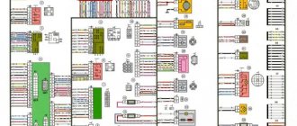
TsBKE pinout
The location of the TsBKE contact connectors is shown in the figure:
- Enter exit. CAN bus (L – line)
- Enter exit. CAN bus (H – line)
- Enter exit. Rear window heating control
- Exit. Heated windshield relay
- Entrance. Hazard switch
- Entrance. Trunk lock actuator switch
- Entrance. Windshield Wiper Switch (Intermittent Position)
- Entrance. Windshield Wiper Switch (Low Speed Position)
- Entrance. Windshield Wiper Switch (High Speed Position)
- Entrance. Windshield washer
- Exit. Seat heating relay
- Exit. Heated windshield switch
- Enter exit. Lighting control module (Automatic lighting mode) – for 21900-3840080-20 Not activated – for 21900-3840080-10
- Terminal 15
- Entrance. Engine compartment lamp switch
- Entrance. Light switch (Left side direction indicators)
- Entrance. Light switch (Starboard direction indicators)
- Enter exit. Headlight high beam relay control
- Exit. Low beam relay
- Entrance. Lighting control module (Low beam mode)
- Exit. Alarm sound
- Exit. Windshield Wiper Motor (Low Speed Mode)
- Terminal 30 (Turn signals, daytime running lights, low current signals)
- Exit. Turn indicators "Left side"
- Exit. Direction indicators "Right side"
- Exit. Daytime Running Lights
- Enter exit. Park position windshield wiper
- Exit. Windshield Wiper Motor (High Speed Mode)
- Terminal 30 (Windshield wiper motor, interior lighting)
- Terminal 30 (Power windows, door and trunk locks)
- Exit. Trunk lighting – for 21900-3840080-20 Not activated – for 21900-3840080-10
- Exit. Power window switch power supply
- Entrance. Rear left door power window switch - for 21900-3840080-20 Not activated - for 21900-3840080-10
- Entrance. Rear right door power window switch - for 21900-3840080-20 Not activated - for 21900-3840080-10
- Entrance. Front right door power window switch
- Exit. Electrically controlled mirror right (Mode “Up / Down”) – for 21900-3840080-20 Not activated – for 21900-3840080-10
- Exit. Electrically controlled mirror right (Mode “Right / Left”) – for 21900-3840080-20 Not activated – for 21900-3840080-10
- Enter exit. LIN bus
- Housing (Low Current Loads)
- Exit. Trunk lock drive
- Exit. Interior lighting unit
- Entrance. Airbag activation signal
- Entrance. Rain sensor sensitivity regulator – for 21900-3840080-20 Not activated – for 21900-3840080-10
- Entrance. Trunk light switch
- Enter exit. CAN bus (L – line)
- Enter exit. CAN bus (H – line)
- Entrance. Front right door switch
- Entrance. Rear passenger door switch
- Autostart (for Lada Connect system)
- Entrance. Front left door switch
- Exit. Car interior lighting (Energy saving mode)
- Exit. Driver's door lock motor
- Exit. Front left door power window
- Exit. Front right door power window
- Exit. Rear left door power window – for 21900-3840080-20 Not activated – for 21900-3840080-10
- Exit. Rear right door power window – for 21900-3840080-20 Not activated – for 21900-3840080-10
- Housing (High Current Loads)
- Exit. Passenger door lock motors
- Exit. General "starboard"
- Exit. General "left side"
CBKE errors
- * there is no fault code in TsBKE 21900-3840080-10;
- If an “active” fault code is detected, perform the checks outlined in the “diagnostics” column;
- After troubleshooting, clear fault codes using a diagnostic tool.
Advice
: To read errors in electronic units, car owners often use the ELM327 adapter (buy on Ali) and the OpenDiagPro program (the mobile version of OpenDiag does not support working with TsBKE)
Deciphering fault codes
:
- B1002 Open in driver lock control circuit
- B1004 Open in the front left window control circuit
- B1006 * Open in the rear left window control circuit
- B1008 Open in the alarm sound control circuit
- B1010 Open in the trunk gear motor control circuit
- B1012 Open in the passenger lock control circuit
- B1014 Open in the front right power window control circuit
- B1016 * Open in the rear right window control circuit
- B1017 ROM checksum error of the central unit of body electronics
- B1018 Short circuit in the rear window heating relay coil circuit
- B1019 Short circuit in the windshield heating relay coil circuit
- B1020 Short circuit in the seat heater relay coil circuit
- B1021 Wiper malfunction
- B1023 Short to ground or overheating in the control circuit of the common board bus
- B1027 Malfunction of the power window control keys in the passenger doors
- B1028 * Short to ground in the rain sensor sensitivity regulator circuit
- B1030 Open circuit (lamp burnout) of daytime running lights
- B1031 * Open circuit in the rain sensor sensitivity regulator circuit
- B1033 Open (lamp burnout) in the left turn signal circuit
- B1034 Open (lamp burnout) in the right turn signal circuit
- B1040 Open or short to ground in the low beam headlight relay coil circuit
- B1041 * Short circuit in the automatic lighting control relay coil circuit
- B1042 Short circuit in the high beam relay coil circuit
- B1043 Short circuit in the low beam relay coil circuit
- U1044 Lack of communication with MDV
- U1045 Communication error with MDV
- U1046 * Communication error with rain and light sensor
- U1047 * No communication with rain and light sensor
- U1048 CAN bus fault
- B1049 High voltage on-board network
- B1050 Low voltage on-board network
- B1051 * Short to ground in the right mirror control circuit
- B1052 * Left Mirror Control Circuit Malfunction
- B1057 Internal malfunction of the MDV
TsBKE connectors
- XP1 connector - Molex 34729-0080
- XP2 connector - Molex 31372-1000
- connector X3 - Molex 34729-0200
- connector X4 - Molex 31372-1100