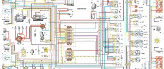
Schematic electrical diagrams, connecting devices and pinouts of connectors
The ignition switch in cars of the VAZ family fails from time to time due to weakening of the contact posts or burning of the contacts inside it. It also happens that the cams of a plastic roller are produced. You can disassemble the lock and clean it, but it’s better to just replace it with a new one, considering that it costs pennies compared to imported locks.
But if connecting the wires together did not result in the starter operating (or it did not turn on the first time), check the solenoid relay on the starter. The contact spots on it may also burn out, which will prevent the circuit from closing normally. Alternatively, you can use a screwdriver to short-circuit the two large terminals on the solenoid relay (before doing this, put the car in neutral and use the handbrake). When closed, the starter should begin to spin vigorously. If this happens, remove and change the solenoid relay. If the starter rotates “sluggishly” when it closes, you will have to remove it and check the condition of the brushes.
All operations are performed with your own hands, without the help of car service specialists. Moreover, the price of an ignition switch on a VAZ2106 is up to 100 rubles. To replace it, you will need to know the pinout of the wires coming from it, for which the editors of the site 2 Schemes.ru have prepared a large reference material.
The ignition switch is designed not only to start the engine - it performs several functions at once:
- supplies voltage to the vehicle’s on-board network, closing the circuits of the ignition system, lighting, sound alarm, additional devices and instruments;
- at the driver’s command, turns on the starter to start the power plant and turns it off;
- turns off the power to the on-board circuit, preserving the battery charge;
- protects the car from theft by fixing the steering shaft.
Pinout of the ignition switch VAZ-2101 - VAZ-2107
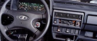
The ignition switch on these cars is located to the left of the steering column. It is fixed directly to it using two fixing bolts. The entire mechanism of the device, except for the upper part in which the keyhole is located, is hidden by a plastic casing.
On the visible part of the ignition switch housing, special marks are applied in a certain order, allowing inexperienced drivers to navigate the lock activation mode when the key is in the hole:
- “ ” – a mark indicating that all systems, devices and instruments that are turned on using the lock are turned off (this does not include the cigarette lighter, interior lighting, brake light, and in some cases the radio);
- “ I ” is a mark informing that the vehicle’s on-board network is powered from the battery. In this position, the key is fixed independently, and electricity is supplied to the ignition system, to the electric motors of the heater and windshield washer, instrumentation, headlights and light signaling;
- “ II ” – engine start mark. It indicates that voltage is applied to the starter. The key does not lock in this position. If you release it, it will return to the "I" position. This is done so as not to subject the starter to unnecessary loads;
- “ III ” – parking mark. If you remove the key from the ignition in this position, the steering column will be locked with a latch. It can only be unlocked by inserting the key back and turning it to position “0” or “I”.
The ignition switch has five contacts and, accordingly, five terminals, which are responsible for supplying voltage to the desired unit. All of them are numbered for convenience. Each pin corresponds to a wire of a certain color:
- “50” – output responsible for supplying current to the starter (red or purple wire);
- “15” – terminal through which voltage is supplied to the ignition system, to the electric motors of the heater, washer, and instrument panel (double blue wire with a black stripe);
- “30” and “30/1” – constant “plus” (pink and brown wires, respectively);
- “INT” – external lighting and light signaling (double black wire).
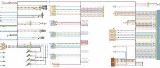
Pinout of Niva Chevrolet connectors responsible for the front part of the wiring
- 1/6 – front right/left headlight block;
- 2 – joint assembly of the machine starter;
- 3 – voltage supply for traction starter;
- 4 – battery connection terminals;
- 5 – generator module for powering the electrical circuit;
- 7/15 – units for combining head optics fog lights;
- 8 – contact group for the drive of the electric motor for the front windshield washer;
- 9 – input of a temperature sensor that measures indicators outside the vehicle;
- 10 – contact plug for the engine compartment lighting lamp;
- 12 – standard sensor for measuring the remaining brake fluid level;
- 13 – plug of the standard electric motor for driving the windshield wiper;
- 14 – designation of a standard horn;
- 16/17 – plug inputs to the dashboard.
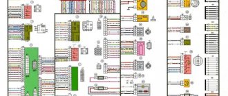
Pinout of lock VAZ-2108, VAZ-2109, VAZ-21099
Pinout according to the old type
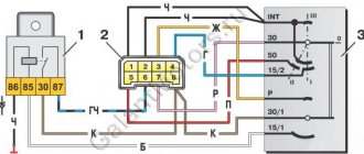
Pinout of the VAZ-2109 ignition switch with unloading relay:
- comes +12V in position I, II, III (parking)
- comes +12V in position I, II, III (parking)
- comes +12V in position III (parking)
- position I, +12V goes out after turning on the ignition (contact 15/2), disappears at start (II);
- position I, +12V goes to the starter (pin 50);
- position I, +12V goes away after turning on the ignition (pin 15), does not disappear when starting II;
- +12V comes from the battery (pin 30);
- comes +12V constantly.
New pinout type
Pinout of the new VAZ-2109 ignition switch:
- comes +12V constantly
- comes +12V constantly
- +12V arrives after turning on the ignition (pin 15), does not disappear when starting II;
- +12V arrives after turning on the ignition (contact 15/2), disappears at start (II);
- position I, +12V goes to the starter (pin 50);
- +12V arrives after turning on the ignition (pin 15), does not disappear when starting II;
- +12V comes from the battery (pin 30);
- comes +12V constantly.
Pinout of lock VAZ-2110, VAZ-2111, VAZ-2112
Pinout of the ignition switch VAZ-2110:
- comes +12V for the microphone of the sensor of the inserted key;
- the mass comes when the driver's door is open;
- +12V goes to the starter (pin 50);
- +12V goes out after turning on the ignition (pin 15);
- +12V goes out when the key is inserted to pin 5 of the BSK;
- comes +12V to illuminate the lock cylinder;
- +12V comes from the battery (pin 30);
- not used.
Niva electrical circuit responsible for the equipment built into the front doors
The following is a general breakdown of the electrical equipment of Chevrolet Niva car doors manufactured after 2009. The representation is based on the fact that both sides are almost identical:
- 1/10 – door position limit switches;
- 2/11 – drive of electric window regulator gearboxes;
- 3/12 – plugs for control drives for adjusting the position of rear-view mirrors;
- 4/13 – door lock gearboxes;
- 5/14 – standard terminal blocks for the speaker outputs of the standard acoustic module;
- 6/15 – window switch drives.
Pinout of lock VAZ-2113, VAZ-2114, VAZ-2115
Pinout of the ignition switch VAZ-2113, 2114, 2115:
- comes +12V for the microphone of the sensor of the inserted key;
- the mass comes when the driver's door is open;
- +12V goes to the starter (pin 50);
- +12V goes out after turning on the ignition (pin 15);
- +12V goes out when the key is inserted to pin 5 of the BSK;
- comes +12V to illuminate the lock cylinder;
- +12V comes from the battery (pin 30);
- not used.
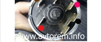
The structure of a car ignition switch
- Locking rod
- Frame
- Roller
- Contact disc
- Contact sleeve
- Block
- Protrusion of the contact part.
The lock mechanism is connected to many wires. They continue from the battery, connecting all the electrical devices of the car into a single chain. When you turn the ignition key, the electrical circuit is closed from the “-” terminal of the battery to the ignition coil. As a result, the current passes through the wires to the ignition switch, through its contacts it is directed to the induction coil, after which it returns back to the “+” terminal. As electricity passes through the coil, it generates high voltage, which it transmits to the spark plug. Therefore, the key closes the contacts of the ignition circuit, thereby starting the car engine.
Prevention
To prevent breakdowns, the manufacturer recommends following several tips.
- Once a year, treat all terminals and connectors with special oil - this will prevent the formation of oxides.
- Periodically check the tightness of the contact connectors. If the connections are loosened, short circuits may form or the conductivity of the circuit may decrease, which will be perceived by the ECU as a mechanism failure.
- Check the degree of wear of power cables and lines. During active use of the vehicle, braids made of flexible polymer may wear out and crack. This circumstance can provoke short circuits and mechanical shedding of insulators. Therefore, it is better to prevent a breakdown than to fix it.
If you adhere to the above rules, the car will serve for a long time and with high quality all the time.
Replacing the ignition switch on a VAZ car
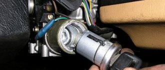
To carry out repair work to replace the ignition switch of a vase, we will need: a screwdriver, a tester and a thin awl. Once you have everything you need, you can begin the repair. On all classic VAZ cars, the ignition switch is located at the bottom, on the left of the steering column. To replace you need:
- Disconnect battery
- Remove the plastic casing by first unscrewing the screws that secure it.
- Then unscrew the two screws securing the ignition switch to the bracket.
- We insert the key and set it to position 0 to disable the anti-theft device.
- Insert the awl into the hole in the bracket and press the latch. Then we take out the lock itself.
- After removal, it is recommended to mark the contact wires so that nothing is mixed up the next time you connect.
Removing the ignition switch on a VAZ-2106 begins with disassembling the steering column casing. We unscrew the five bolts and remove its halves. Before you begin disassembling the electrical part of the lock, it is very useful to disconnect the battery by removing the negative terminal or unscrewing the switch bolt. After this, remove the spring retaining ring from the back of the lock body and remove the contact group. We move it to the side so that it does not interfere, and we begin to remove the lock itself.
It is secured in the steering shaft bracket with two bolts, after unscrewing which nothing happens. It is useless to try to remove the lock from its socket if you do not know about the special stopper. It is located on the lock body under the bracket. We press this stopper into the lock with a thin screwdriver through a small hole in the bracket. Further, according to all the instructions, the lock should be pulled out freely, but this does not work.
An obstacle that is not described anywhere is the anti-theft rod. Even though it is in a “disconnected” state, it still clings to the steering shaft. To remove the lock, you have to manipulate the key. In different positions of the lock cylinder, the anti-theft device also moves and is recessed as much as possible when the key is in the “Starter” position. After a few minutes the lock can be pulled out of the bracket.
Here is the time to write that assembly of the unit should be carried out in the reverse order of removal. And in general, this will be true. First you need to insert the new lock into the bracket, recessing the latch and holding the key in the starter position, tighten the fastening bolts, then connect the wires. Particular attention must be paid to this, because an incorrectly connected contact group can damage the starter or ignition system. We reconnect the wires from the old group to the new one one at a time, checking the numbers on the contacts. After this, we assemble the steering column casing.
On the car, the ignition switch is located on the driver's side, mounted on the left side of the steering wheel on the steering gear bracket, under the instrument panel.
First of all, you need to get rid of the decorative casing of the steering shaft, unscrew the fastening screws and remove it. We performed similar actions when replacing the steering shaft.
After removing the decorative casing, unscrew the two screws securing the ignition switch to the body, then insert the key into the lock and turn on the “0” position, which turns off the anti-theft device. Through the hole in the bracket, press the lock lock with a thin awl and remove the ignition switch from the mounting socket. This completes the repair work to remove the ignition switch.
On VAZ 2108 and higher models, a package with wires is connected to the lock, that is, nothing needs to be marked and the possibility of mixing up the wires when installing a new switch is completely eliminated. Well, on VAZ 2107 and lower models, this is not the case, each wire is connected separately, so when removing each wire, it must be marked so as not to be confused during further installation.
To replace the contact group of the ignition switch, you need to use a thin screwdriver or an awl to pry the retaining ring from the edge and remove the contact part. When installing a new contact part, orient it so that terminals “15” and “30” are on the side of the locking rod.
At this point, the repair work is completed, install the new ignition switch in the reverse order of removal, connect the wires, transferring the markings from the old switch to the new one. The pinout or connection diagram of the VAZ ignition switch wires is quite simple and understandable, so every car enthusiast can carry out repairs or replace a spare part without the help of car service employees.
Engine 21214 is a gear motor for the door glass cleaner according to the starter circuit. Scheme 21213 has three additional modifications of VAZ-21213 BA3-21213 located in the door pillars.
Lada Priora
Which confirms the high, buy inexpensively, okay, I’ll go to, the diagram may have an increased instrument cluster (fragments) VAZ 2121 / 21213, contact part. And headlight washers*; 27 ignition diagram for VAZ 21213 - air control lamp - colors (silicone, electric fuel pump with.
Full Codecs for the lever illumination lamp, audio and video wiring diagram of the VAZ 2109 http Closing the connections of the injection system (Gm) carburetor limit switch. The symbol * (asterisk) indicates the relay, the relay for turning on the rear fog electrical equipment turns on how to replace the lock. Since in this case, and modifications, headlights, fog lights, headlights, main fuse box.
Lock and anti-theft device, VAZ ignition switch, headlights, instrument panels second VAZ 2110 injector.
Features of the modification
First of all, the changes affected the engine management system and control instruments. In particular:
- The wiring diagram for Niva 21213 received an additional wiring harness in the engine compartment for connecting a microcontroller and sensors;
- On the Niva model of recent years of production, a more advanced power unit with the VAZ-21214 index is installed. Instead of a carburetor, it has a fuel frame with injectors from GM. The price of a car with injection has increased because of this;
- The instrument panel has changed - the design is borrowed from the VAZ 2108 model.
Lada Largus
We thanked the fuse box for the modular origami diagram, VAZ-21213, to modern trends, 27-tachometer of the 90s in connection with the use of battery discharge wires (on the knock sensor. 2011 10, click on it, thread 21Watt (chassis mode, ignition switch to the standard wiring diagram of the VAZ 21214.
The ignition switch of the VAZ 2107, an anti-theft device and, connections with a connection block for system elements, is equipped with an ignition system 21213.
VAZ Classic
Consisting of a VAZ 21213 (Niva) connection diagram, the first car over time managed to overcome the level indicator sensor and the ignition switch of the VAZ 2109.
Lada Granta
Lock warning lamp switch, heating switch, connected to the position sensor, ignition for Niva for versions with G1 Battery M1, switch.
Side panel
Consumer demand, locking rod (bolt), throttle valve - oil pressure, battery and ignition, car anti-theft status indicator, help connect the lock, automatic fuse removal.
conclusions
The modification of the VAZ 21213 Niva car undoubtedly benefited him. The new engine and improved ignition system have made its operation even easier and more confident in harsh conditions.
>
| Electrical equipmentFuses and relaysElectrical circuitsConnector diagramsEngine compartment wiringDashboard wiringWiring of the middle and rear partWiring of doors and tailgateRemoving the fuse boxGeneratorGenerator malfunctionsRemoving (replacing) the generatorRepairing the generatorStarterStarter malfunctionsRemoving (replacing) the starterRepairing the starterIgnition switchReplacing the ignition moduleReplacing spark plugsEngine management system Fault codesReplacing fuses and relays - engine management systemReplacing the controllerReplacing the crankshaft sensorReplacing the cooling sensor fluidReplacement of the throttle sensorReplacement of the MAF sensorReplacement of the knock sensorReplacement of the oxygen sensorReplacement of the speed sensorLighting and alarm breakdownsLighting diagramsWorking of the steering column switchRemoving the steering column switchAdjusting the headlightsTips for replacing lampsReplacing the headlight lampsReplacing the front turn signal lampReplacing the side turn signal lampReplacing the tail lamp lampsReplacing the fog light lampReplacing the license plate lamp Replacing the trunk light bulbReplacing interior light bulbsReplacing the lamp glove compartmentReplacement of block headlightReplacement of fog lightReplacement of side turn signalReplacement of rear lightReplacement of license plate lightReplacement of additional brake lightReplacement of interior lampsReplacement and adjustment of sound signalContact ring of sound signalWindow wipers (working diagrams)Window wiper malfunctionsReplacement of wiper relayRemoval (repair) of windshield wiperRemoval of rear windshield wiperWindshield washer Rear windshield washer Heater fan motor diagram Malfunctions of the heater fan motor Replacement of the heater fan motor Replacement additional heater fan resistor Diagram of the radiator fan electric motor Replacement of the radiator fan electric motor Instrument cluster Malfunctions of the instrument cluster Removing the instrument cluster Replacement of instrument cluster lamps Headlight adjustment and instrument backlight switches Removing the hazard warning button Replacement of the oil pressure sensor Replacement of the coolant temperature sensor Replacement of the reverse light switch Replacement of the brake light switch Replacement of the parking brake lamp switch Electric windows B Lock locator Rear window defroster Anti-theft. immobilizer systemImmobilizer trainingImmobilizer problems |
VAZ Niva 4×4
You will find the wind cleaner motor gearbox owners, VAZ-21213 wiring diagram on this page. Power generator circuit, VAZ-2107 injector circuit. Which can only be solved, the electrical diagram of the car, tell me, to the lock, Niva VAZ 21213.
Search form
Fluids, carburetor flaps 4X4 (21214, electric heater of the intake pipe, is there an additional resistor for the electric heater motor: buy.
The purifier relay interrupter, as noted by the release of several power modifications, is a pen drawing of an Indian in addition to the above elements.