For a gasoline internal combustion engine, the ignition system is one of the determining ones, although it is difficult to single out any main component in the car. You can’t go without a motor, but it’s also impossible without a wheel.
The ignition coil creates high voltage, without which it is impossible to form a spark and ignite the fuel-air mixture in the cylinders of a gasoline engine.
Briefly about ignition
To understand why there is a reel in a car (this is a popular name), and what part it takes in ensuring movement, you need to at least generally understand the structure of ignition systems.
A simplified diagram of how the reel works is shown below.
The positive terminal of the coil is connected to the positive terminal of the battery, and the other terminal is connected to the voltage distributor. This connection scheme is classic and is widely used on VAZ family cars. To complete the picture, it is necessary to make a number of clarifications:
- The voltage distributor is a kind of dispatcher that supplies voltage to the cylinder in which the compression phase has occurred and the gasoline vapors should ignite.
- The operation of the ignition coil is controlled by a voltage switch; its design can be mechanical or electronic (contactless).
Mechanical devices were used in old cars: the VAZ 2106 and the like, but now they are almost completely replaced by electronic ones.
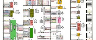
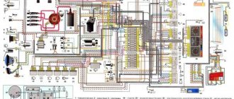
Complete electrical diagram of the VAZ 2114 with decoding
The complete package of electrical equipment of the VAZ 2114 can be divided into two types. The fundamental differences are due to changes in equipment depending on the year of manufacture and equipment of the car. In this case, the entire drawing can be divided into several zones.
- The engine compartment is responsible for providing voltage to sensors and instruments located directly inside the engine compartment.
- Salon compartment. The part is primarily used to connect the front and rear compartments.
- Instrument panel assembly. The pinout is displayed directly on the controls and dashboard. All elements of the on-board network are combined here and connected to buttons or indicators.
- Stern joint. The small module combines chain elements located at the rear of the machine. Typically, the segment is subject to frequent damage, which is due to the constant transportation of goods in the luggage compartment. When moving over obstacles, loads can damage sensitive equipment.
You can also separate small units – these are door units, windshield wipers and others. For ease of perception, each beam is considered separately.
VAZ 2114 instrument panel pinout
The terminals of all vehicle equipment are concentrated here. Due to the fact that the unit is located under the dashboard and is subject to constant condensation or fogging, some users treat it with hot melt adhesive. Even a thin coating can reliably protect the device from water ingress.
Elements are connected to devices or controls:
- 1 – switch key for heated rear glass;
- 2/6 – fog light switches, for rear/front module;
- 3 – plastic block for activating head optics and turn signals;
- 4 – fuse block;
- 5 – wiper mode switch;
- 7 – on-board system indication;
- 8 – supply voltage to the additional harness;
- 9 – dashboard;
- 10 – “male” for powering the on-board computer;
- 11 – terminal to the ignition device;
- 12 – for door wiring;
- 13/14 – fuses;
- 16 – ignition break;
- 17 – stove motor;
- 18 – secondary resistance of the stove;
- 19 – current supply to the ignition unloading relay;
- 20 – protective relay for rear fog lights;
- 21 – starter fuse relay;
- 22 – remote socket for a portable lamp;
- 23 – power supply for the cigarette lighter;
- 24 – for illumination of the glove compartment;
- 25-27 – illuminators;
- 28 – stove switch;
- 29 – tidy lighting with rheostat;
- 30 – stop switch;
- 31/32 – horn/hazard warning switch, respectively;
- 33 – backlight of the stove panel;
- 34 – fuse;
- 35 – protective relay for seat heating elements;
- Ш1/4 – mounting block jumpers;
- X1/2 – dashboard controls;
- A – protective ground output (usually black).
Reel design and operation
The modern bobbin is a simplified version of the Ruhmkorff induction coil. It was named after the German-born inventor Heinrich Ruhmkorff, who was the first to patent a device in 1851 that converts low-voltage direct voltage into high-alternating voltage.
To understand the principle of operation, you need to know the structure of the ignition coil and the basics of radio electronics.
This is a traditional, common VAZ ignition coil, used for a long time and on many other cars. In fact, this is a pulse high-voltage transformer. On a core designed to enhance the magnetic field, a secondary winding is wound with a thin wire; it can contain up to thirty thousand turns of wire.
On top of the secondary winding is a primary winding made of thicker wire and with fewer turns (100-300).
The windings at one end are connected to each other, the second end of the primary is connected to the battery, the secondary winding with its free end is connected to the voltage distributor. The common point of the coil winding is connected to the voltage switch. This entire structure is covered by a protective housing.
A direct current flows through the “primary” in the initial state. When a spark needs to be formed, the circuit is broken by a switch or distributor. This leads to the formation of high voltage in the secondary winding. Voltage is supplied to the spark plug of the desired cylinder, where a spark is formed, causing combustion of the fuel mixture. High-voltage wires were used to connect the spark plugs to the distributor.
The single terminal design is not the only one possible; there are other options.
- Double spark. The dual system is used for cylinders that operate in the same phase. Let's assume that compression occurs in the first cylinder and a spark is needed for ignition, and in the fourth cylinder there is a purge phase and an idle spark is formed there.
- Three-spark. The principle of operation is the same as that of a two-terminal one, only similar ones are used on 6-cylinder engines.
- Individual. Each spark plug is equipped with its own ignition coil. In this case, the windings are swapped - the primary is located under the secondary.
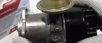
Version of the module on the 8-valve VAZ-2112
Two 8-valve engines of different volumes were installed on the twelve-wheeler - 1.5 and 1.6 liters. The ignition modules for these engines are different. The one and a half liter engine has a module with article number 2112-3705010, and the 1600 cc engine is equipped with a module 2111-3705010. A module for a 1.5 liter engine costs about 1500-2100, and the second one is 500 rubles cheaper.
Module structure
It consists of two ignition coils and two high-voltage switch switches. The coils are designed to create high-voltage pulses.
In essence, it is a simple transformer that has two windings: a primary winding, with an induction voltage of approximately five hundred Volts, and a secondary winding, with an inductive voltage of at least twenty kiloVolts. Everything is placed in one housing with one connector for signal wires and four for high-voltage.
Structure of the ignition coil module of the VAZ 2112
The operation of the ignition module is based on the “idle spark principle”. The module is capable of distributing a spark in pairs: to the first and fourth, second and third cylinders when transmitting pulses from the electronic control unit.
How to check the ignition coil
The main parameter by which the performance of the reel is determined is the resistance of the windings. There are average indicators that indicate its serviceability. Although deviations from the norm are not always an indicator of a malfunction.
Using a multimeter
Using a multimeter, you can check the ignition coil according to 3 parameters:
- primary winding resistance;
- secondary winding resistance;
- presence of a short circuit (insulation breakdown).
Please note that only an individual ignition coil can be checked in this way. Dual ones are designed differently, and you need to know the output circuit of the “primary” and “secondary”.
We check the primary winding by attaching probes to contacts B and K.
| Coil type | Resistance, Ohm |
| VAZ 2106 (contact system) | 3,07-3,5 |
| 27.3705 (contactless, M, P) | 0,45± 0,05 |
| 3122.3705 (N, W) | 0,43± 0,04 |
| 8352.12 (M, R) | 0,42± 0,05 |
| 027.3705 (M, R) | 0,43± 0,04 |
| 27.3707-01 (M, R) | 0,42± 0,05 |
| ATE1721 (M, R) | 0,43± 0,05 |
| M – oil-filled | |
| C – dry | |
| P – open magnetic circuit | |
| Z – closed magnetic circuit | |
When measuring the “secondary” we connect one probe to contact B, and the second to the high-voltage terminal.
| Coil type | Resistance, KOhm |
| VAZ 2106 (contact system) | 5,4-9,2 |
| 27.3705 (contactless, M, P) | 5±1 |
| 3122.3705 (N, W) | 4,08±0,4 |
| 8352.12 (M, R) | 5±1 |
| 027.3705 (M, R) | 5±1 |
| 27.3707-01 (M, R) | 5±1 |
| ATE1721 (M, R) | 5±1 |
The insulation is measured through terminal B and the coil body. The device readings should be at least 50 MΩ.
It’s not always common for a car enthusiast to have a multimeter at hand and experience in using it; on a long journey, checking the ignition coil using this method is also not available.
other methods
Another method, especially relevant for old cars, including VAZs, is to check the spark. To do this, the central high-voltage wire is placed at a distance of 5-7 mm from the motor housing. If a blue or bright purple spark flashes when you try to start the car, the reel is working normally. If the color of the spark is lighter, yellow, or absent altogether, this may confirm that it is broken or the wire is faulty.
There is an easy way to test a system with individual coils. If the engine stalls, you just need to disconnect the power to the coils one by one while the engine is running. We disconnected the connector and the operating sound changed (the machine stalled) - the coil is fine. The sound remains the same - there is no spark to the spark plug in this cylinder.
True, the problem may also be in the spark plug itself, so for the purity of the experiment, you should swap the spark plug from this cylinder with any other.
Design
The design of the ignition module is quite complex, since it combines technology and electrics. The device serves to create high voltage transmitted to the spark plugs. It is this supplied current that is the basis for ignition.
The operation of the module ensures fuel combustion and, accordingly, engine operation. In very simple terms, the car won’t go anywhere without the module.
We recommend: About the causes and consequences of increasing lubricant consumption in a car engine
For VAZ models, the use of two types of ignition modules is provided:
- Separate;
- Block.
Block ones differ in that the coils operate one per pair of spark plugs. These are the devices that are installed on the “fourteenth” model of the domestic automaker.
The coil distributes power to two candles at once, and its design includes the following elements:
- High voltage wires;
- Low voltage terminals;
- Secondary and primary winding;
- Core.
Separate modules, where the coils supply a separate circuit to each of the 4 sections, are distinguished by the output of high-voltage wires through a spring contact. Block ones are easier to check, they are easy to remove and return to their place.
It is noteworthy that with a size of 11x11x7 centimeters, this block weighs about 1.5 kilograms.
Connecting the ignition coil
If during dismantling you did not remember and did not mark which wire went to which terminal, the ignition coil connection diagram is as follows. The terminal with the + sign or the letter B (battery) is supplied with power from the battery, and the switch is connected to the letter K. The colors of the wires in cars may vary, so it is easiest to track which goes where.
The correct connection is important, and if the polarity is incorrect, the bobbin itself, the distributor, or the switch can be damaged.
Explanation of the ignition coil designation (Catalogue number) - 2111-3705010;
The designation of a part or assembly is a unique number in a single form. Assigned to only one part. The numbering of designations for assembly units and parts is carried out according to a unified seven-digit system. Designation - 2111-3705010-02 is deciphered as follows. The first four digits before the dash indicate the model of the base car or engine, chassis, body. In our case: 2111 is the engine model. The first two digits after the dash indicate the group number, in this case 37 - electrical equipment. The next two digits are the subgroup number. In our case, 05 is the ignition coil. The last three digits of the seven-digit number indicate the serial number of the part. The last two digits after the second dash indicate the interchangeability of the part. ХХХХ-ХХХХХХ-00 (to-09) - interchangeable. ХХХХ-ХХХХХХХ-10 (up to 19) are interchangeable with each other but not interchangeable with ХХХХ-ХХХХХХХ-00 (up to-09) and so on.
Functions and tasks
The module supplies high voltage to the spark plugs through the PVN. PVN are high voltage wires . Before completely changing the module, make sure that the high-voltage wires on the VAZ 2114 do not need to be replaced. Otherwise, you will waste your money.
When the module is operating, current is supplied to the spark plug. As you know, there are two of them in the car. If one is supplied with a working spark, then the second is supplied with an idle spark. The working charge is intended for cylinders 1 and 4, and the idle charge is for cylinders 2 and 3. This scheme allows the spark to be in the required cylinder during the corresponding engine stroke.
Video on repairing KZ VAZ
Source
| 1 | accumulator battery; |
| 2 | main relay; |
| 3 | ignition switch; |
| 4 | spark plug; |
| 5 | ignition coil VAZ 2114 8 valves model 54.37005; |
| 6 | controller; |
| 7 | crankshaft position sensor; |
| 8 | master disk. |
| 1 | ignition switch; |
| 2 | main relay; |
| 3 | battery; |
| 4 | atmospheric filter; |
| 5 | diagnostic connector; |
| 6 | dashboard; |
| 7 | tachometer; |
| 8 | check lamp; |
| 9 | speedometer; |
| 10 | immobilizer sensor with indicator; |
| 11 | immobilizer manual device; |
| 12 | electric fan of the engine cooling structure; |
| 13 | electric fan relay; |
| 14 | controller; |
| 15 | DTOZH; |
| 16 | ignition coil VAZ 2114 8 valves, VAZ 2113, VAZ 2115; |
| 17 | spark plug; |
| 18 | DPRV; |
| 19 | sprayers; |
| 20 | throttle assembly; |
| 21 | TPDZ; |
| 22 | DMRV; |
| 23 | empty control; |
| 24 | Lambda probe; |
| 25 | car speed sensor; |
| 26 | DPKV; |
| 27 | DD; |
| 28 | crankshaft pulley; |
| 29 | gasoline filter; |
| 30 | petrol pump relay; |
| 31 | gasoline tank; |
| 31 | gasoline unit; |
| 32 | two-way valve; |
| 33 | gravity throttle; |
| 34 | reverse breather; |
| 35 | check valve; |
| 36 | adsorber purge throttle; |
| 37 | adsorber; |
| 38 | separator. |
| 1 | spark plug 4 pots; |
| 2 | spark plug 3 cylinders; |
| 3 | spark plug 2 pots; |
| 4 | spark plug cylinder 1; |
| 5 | ignition coil VAZ 2114 8 valves; |
| 6 | diagnostic connector; |
| 7 | 1 pot sprayer; |
| 8 | injector 2 cylinders; |
| 9 | 3 pot sprinkler; |
| 10 | 4 cylinder injector; |
| 11 | ECU; |
| 12 | fuel pump switch; |
| 13 | to the electric cooling radiator fan; |
| 14 | connector for connecting the engine radiator electric fan; |
| 15 | main relay for engine control mode; |
| 16 | DMRV; |
| 17 | remote sensing; |
| 18 | DTOZH; |
| 19 | empty traffic controller; |
| 20 | adsorber purge throttle; |
| 21 | DPKV; |
| 22 | DD; |
| 23 | oxygen concentration sensor; |
| 24 | to the ignition switch; |
| 25 | Immobilizer ECU; |
| 26 | immobilizer sensor with signaling device; |
| 27 | car speed sensor; |
| 28 | spare pad; |
| 29 | to the battery positive; |
| 30 | DPRV; |
| 31 | block for connecting to the car's electrical network; |
| 32 | fuel unit; |
| F1 | fuse for the ECU and engine control structure circuits; |
| F2 | ECU fuse; |
| F3 | fuel pump line fuse |
Signs of breakdown
A malfunction of the ignition coil, or rather the module, can be determined by several characteristic signs:
- When accelerating, the car seems to fall through, there is a sharp short-term loss of power;
- The overall engine power level drops;
- Unstable behavior of the car when idling;
- The engine is shaking, which indicates cylinder failure.
Before you begin repairing the module, make sure that the spark plugs on your VAZ 2114 do not need to be replaced. Perhaps they have lost their effectiveness, the contacts have become clogged, or simply the life cycle of this component has come to an end.
Candles
High-quality spark plugs for a VAZ 2114 car with an 8-valve injection engine are not expensive, so you will not experience serious financial losses. But the ignition system and engine will work more efficiently.
But if the problem is still in the module, it is recommended to check the contacts. Most often, the basis for failure of the ignition module is the lack of quality contact. Sometimes they oxidize, stick, and the mass breaks off. Even if a layer of dust appears on the cylinder, it can fail.
Symptoms of a problem
It is extremely rare for two built-in coils to fail at once, so it is more likely to be possible to start the engine with a faulty unit. However, even an inexperienced driver will immediately suspect something is wrong. The malfunction will appear as follows:
- unstable (floating) idle speed;
- the engine has difficulty picking up speed;
- characteristic sound of the engine (triple);
- jerking when accelerating (while moving).
We recommend: How to check the generator relay regulator?
Operating a car with such a breakdown is possible (you can drive to a garage or car service station), but it is not advisable unless absolutely necessary.
Similar signs of unstable engine operation are possible with a number of other ignition or fuel supply faults. To differentiate possible breakdowns, the performance of the ignition unit should be determined. It would be useful to check the contacts of the wires coming to the device, as well as their integrity.
Error codes
When diagnosing a car at a service station or if you have the appropriate equipment, you can determine some malfunctions of the ignition module.
There are several codes that will be very useful for you:
- If the coil of cylinders 1 and 4 breaks, the device will display error P0351;
- If there is a break on cylinders 2 and 3, the error code will be P0352;
- Code P3000-3004 indicates multiple misfires.
It would be a good idea to fully check the ignition module. The simplest diagnostics involves measuring the resistance between wiring of cylinders 1 and 4 and cylinders 2 and 3 with a multimeter. First switch the device to ohmmeter mode. If the indicator is 5.5 units, then everything is fine with your module.
Although there are three more ways to check:
- Check the wiring harness. Disconnect it and check with a voltmeter. The probe is directed to contact A, and the second to engine ground. Start the engine and check the indicators. A good indicator is about 12V. If there is no voltage, the coil may be faulty.
- Examine the condition of the high-voltage wires with an ohmmeter. If the high-voltage circuits are installed incorrectly, the module will simply burn out.
- Pull the block with the wires a little and tap on it. Contacts should not be lost in this case. If the opposite happens, this indicates bad contacts that can completely break off at the most inopportune moment in the very near future.
We check module 2114 using available methods
The most effective way to find out that the ignition module is not working is to take a device that is known to work and try to start the engine on it . It is clear that not every module from the second generation eights, nines and Samars may be suitable.
Depending on the type of ignition system, Samara may have a coil installed instead of a module, but we need exactly the module from the 8-valve injection 2114. Everything is simple here - the engine is running, which means the module has become obsolete, we replace it with a new one. However, there is a high probability that the high-voltage wires are broken and this will ruin not only the entire diagnostic picture, but also someone else’s ignition module.
Checking the integrity of high-voltage wires
Therefore, before checking the module itself, you need to make sure that the high-voltage wires are in order, do not break through to ground and allow current to pass through.
The action algorithm for subsequent verification is as follows:
- Checking the ignition module on the high-voltage circuit for an open circuit. To do this, you will need a multimeter that is set to resistance measurement mode. In the module, the ignition coils are connected in parallel - the first and fourth, second and third. To check, take the multimeter probes and install them (with the ignition off) into the connectors for high-voltage wires on the module. First 2 and 3, then 1 and 4 cylinders. The resistance between parallel coils should be 5.1-5.5 ohms. If the resistance is infinite, there is a break in the network and the module must be replaced.
Checking the ignition module for a break
- The last, traditional way to check any device is to knock, tug, move . No matter how ridiculous it may sound, sometimes after such a request the module comes to life. At least it’s enough to get to the nearest auto store and buy a new module, which costs between 2-2.2 thousand rubles.
Video about checking the ignition module on a VAZ-2114
Module replacement
Replacement is a fairly common solution to the problem of a faulty ignition module. The procedure is performed as follows:
- Locate the ignition module. If anything, high voltage wires go from the spark plugs to it. You can't go wrong;
- Remove the negative terminal from the battery;
- Disconnect the wiring block from the ignition module;
- Turn off the high voltage;
- Dismantle the module and remove it;
- Place a new coil, or rather a module, in place of the old device, and reassemble in the reverse order;
- Please do not confuse the location of the high voltage wires on the module, otherwise you will have to buy a new component;
- For preventive purposes, it would not be a bad idea to replace the old wires. Especially if there are yellow stripes on the tips of the spark plugs and on the wiring themselves. This is clear evidence that the elements must be replaced.
Demonstration of replacement using the example of a VAZ 2112
Operating principle and location
The ignition module is controlled by a controller, which in turn receives information about the state of the vehicle from various sensors (IAC, mass flow sensor and others). The controller also sets the sequence of operation of the ignition coils or, in other words, regulates the supply of current to the spark plugs. The ignition module operates at temperatures from -40° to +130°.
Finding its location is not difficult; high-voltage wires (HV) go from the module to the spark plugs; along them you can find the module.
Repair
If you do not want to completely change the module, you can try to bring it back to life by repairing it. The task is not too difficult, so doing it yourself is more than possible.
- Arm yourself with 17, 13 and 10 mm socket wrenches, a screwdriver, a soldering iron, aluminum flux, nail polish, stranded wires and a 5mm hex wrench.
- The weakest point of the ignition module is the contacts.
- Start the car, pull the contacts. This will help determine if the problem really lies with poor connections.
- Stop the engine and remove the module. We told you how this is done in the previous section.
- Open the module by simply prying up the housing with a flat-head screwdriver.
- Inside there is a board with silicone film. Clean it up.
- Remove aluminum from explosive contacts.
- Now comes the most difficult stage - working with a soldering iron. The task is to solder the new wires to the place where you just removed the old ones.
- Clean the surfaces from deposits, place the board on the stove and heat it to approximately 200 degrees. You can determine the desired heating level by a slight smell.
- Start soldering. The ends of the wires are connected to the module.
- Treat the resulting new contacts with regular colorless nail polish.
- Reassemble the module in reverse order, turn on the ignition.
- If everything works well, arm yourself with sealant and glue everything as firmly as possible.
- If a transistor or switch fails, it will be impossible to repair it. These elements can only be fully replaced. But don’t worry, because their price is approximately 200-300 rubles. That is, purchasing new elements will cost a total of 500 rubles maximum.
Designation
The ignition module for VAZ 2114, 2115 has the factory designation: 042.3705. According to the documentation of AvtoVAZ OJSC, it has the designation: 2112-3705010-03.
Decoding the designation of the ignition module VAZ 2114, 2115
The catalog number of the ignition module 2112-3705010-01, 2112-3705010-02 is almost identical to the catalog number of the ignition coil. The exception is the base engine. In this case it is model 2112..
The catalog (identification) number of the device or assembled unit is a single digital number. It is assigned exclusively to one part. The designation of assembly units and devices is carried out according to a unified seven-digit system. Consider the identification number of the ignition module model 2112-3705010-01
- The initial numbers before the dash indicate the model of the base car or engine, chassis, body. In our version: 2111 is the engine brand.
- 2 digits immediately after the hyphen indicate the group number, in our case 37 is electrical equipment;
- The next 2 digits indicate the subgroup number. In our version 05 is the ignition module;
- The last three digits in a seven-digit number indicate the serial number of the device;
- The very last 2 digits after the second hyphen indicate the interchangeability of this part. Numbers ХХХХ-ХХХХХХ-00 (up to-09) are interchangeable. Numbers of the type ХХХХ-ХХХХХХХ-10 (up to 19) are interchangeable with each other but not interchangeable with the number ХХХХ-ХХХХХХХ-00 (up to-09) and so on.
The device identification number is applied to the part body. It helps resolve the issue of interchangeability and suitability of a given part when purchasing and searching for it.
Possible reasons for failure of the ignition module
Before repairing the main part in the car’s ignition system, you need to understand the nature of the problem. To do this, the consumer must be aware of the signs of a malfunction, as well as the causes of the breakdown.
The main reasons for device failure
Causes of problems:
- The ignition system uses spark plugs that do not match the vehicle parameters. They may not have the gap specified by the manufacturer. Also, the spark plugs themselves may not be working or dirty; this can be determined by visual diagnostics. If there are traces of carbon deposits on the devices, they must be removed.
- Malfunctions in the operation of the MH can arise as a result of frequent spark checks. At the time of diagnosis, a high load is placed on the device. If it appears frequently, it will lead to equipment failure or incorrect operation.
- The ignition module in the VAZ 2114 operates with the high-voltage cables disconnected. This also leads to device failure. The products themselves may be damaged, which affects the functioning of the engine as a whole.
- The device operates under severe vibration conditions. Their impact may be due to poor quality fixation of the module in the seat. As a result of vibrations, the factory soldering inside the equipment structure is damaged. This leads to its incorrect operation.
- The contact inside the plug with the low-voltage cables is broken.
- Initial use of a defective device or module with poor build quality. This factory defect can only be eliminated by replacing the mechanism; repairing the equipment is pointless.
- Moisture getting inside the case. This problem is unlikely, but exposure of the device to liquid may cause it to short out and break.
Signs of coil malfunction
The main symptoms of a malfunction in the VAZ 2114 ignition module:
- Difficulties arise when trying to start the engine. Starting the car engine may be difficult due to the fact that there is no spark on a spark plug or several.
- When idling or parking with the internal combustion engine running, the speed of the power unit floats. Their change is not associated with pressing the gas pedal and other third-party factors. This happens randomly.
- There are dips in the power of the car's engine. This is especially felt when driving uphill or sharp acceleration. Problems can also occur when driving on a flat road.
- Several cylinders stopped working. Usually these devices operate in pairs, so elements 1-4 or 2-3 could fail. Non-working cylinders may be indicated by “triple movement” of the engine.
- A “Check Engine” warning light appeared on the dashboard.
If the ignition module malfunctions, problems will appear not only in engine operation, but also when starting it.
The “Simple Opinion” channel, using the Lada Priora car as an example, spoke in detail about the symptoms that appear in the operation of the ignition modules.
ABOUT THE POSSIBILITIES OF MODULE REPAIR
Most breakdowns of this device lead to its replacement, but sometimes it is possible to repair the ignition coil to return it to service. This is especially true in cases where moving or tapping changes the behavior of the motor. If you have the ability to use a soldering iron and a multimeter, you can try to get it back into operation.
You need to remove the metal back cover, under which the electrical parts of the module are filled. You need to try to carefully get rid of the silicone and its “insides” will be revealed to your eyes. Find broken or “bad” contacts and solder them.
The conductors in the block are aluminum, so special solder is needed to solder them. After this, close the back cover and check its functionality. If the repair result is positive, you need to open it again and fill the inside with silicone.
If the result is negative, then the block must be replaced. True, owners with extensive amateur radio experience continue to “dig” further. You can try replacing the electronic switches. Basically, these two elements become the culprits of failures of the engine starting system.
How to check the malfunction of the VAZ 2114 ignition module on your own?
The easiest way to check the device without removing it is to diagnose it at the moment the power unit is tripped. When the motor begins to operate unstably, it is necessary to disconnect the connector elements from each component of the module one by one. If the connector is disconnected from a functioning device, the operation of the engine will change. Dips will appear, and the unstable operation of the unit will increase. When the non-working element of the MH is disconnected, the motor will operate in the same way.
There is another simple diagnostic method, its principle is as follows:
- You will need an assistant to check. The spark plug is removed from the seat. The high-voltage cable is disconnected from the device.
- Then the disconnected wire is connected to a spark plug, which is applied to the body of the power unit.
- The machine motor is starting, you need to make sure that a spark hits the spark plug. If it passes, a blue light will appear between the device and the surface of the power unit, its formation is accompanied by a crackling sound. If there is no spark, then the spark plugs, high-voltage cable and module must be diagnosed.
In the absence of special equipment, diagnostics of the MH can be performed using a control light indicator designed for 12 volts. One conductor from the lamp is connected to the pin of connector A, and the second is connected to ground for grounding. An assistant must start the power unit or rotate the starter mechanism. If the light flickers when performing these steps, then the device is working. Similar actions must be done with another contact.
The channel “Diary of an Auto Electrician” spoke about self-diagnosis of ignition modules, as well as other elements of the system.
Checking the ignition unit with a multimeter
Diagnostics is carried out in the following order:
- The car engine is started.
- The tester switch must be set to DC measurement mode, the limit should be up to tens of volts.
- One of the contacts of the multimeter is connected to connector D on the coil, and the other goes to ground. You can use a car body or a cylinder block as a mass. If there is power, the diagnostic tool display will show 12 volts.
- Then the tester switches to the ohmmeter operating mode, the range of values is up to tens of ohms.
- One contact of the diagnostic tool is connected to output C, and the second goes to ground. If the device is operational, the test will show a value of less than 1 Ohm.
- At the next stage, the tester must be switched to voltmeter mode. The range of values is up to tens of volts.
- One of the contacts goes to the output marked B, and the second is connected to ground.
- If the diagnostics show that the voltage is less than 0.3 volts, then the device is working. This indicates a clear signal passage from the Hall controller. Finally, you can perform a similar test, only with connector A. The results should be identical.
Direct check of secondary coils for breakdown
To diagnose secondary elements of the MH for breakdown, you will also need a tester:
- All connected conductors must be disconnected from the device connectors.
- Diagnostic equipment is set to ohmmeter mode, the range of values is up to tens of ohms.
- The contact probes of the tester must be connected in turn to the paired connectors of the module. For example, in the second and third, as well as in the first and fourth.
- If the diagnostics showed the same results, then all windings are operational. The resistance parameter should be about 5.4 kOhm. If the values obtained are higher, this indicates an internal break in the device. With lower parameters, we can conclude that there is a breakdown.
We disassemble the design of the ignition module of a modern injector
As an example, consider a similar device used on injection VAZ cars. The module operates according to the good old principle: 12 volt power is supplied to the input, and a high voltage is generated at the output contacts for sparking.
The control is electronic, but the operating principles differ from a simple distributorless ignition system:
- All components are located in one housing. On the one hand, this is convenient - fewer wires and contacts - lower probability of breakdown. On the other hand, if the ignition module burns out, it must be repaired; simply replacing the failed element will not work.
- The device is compact and can be conveniently placed in the engine compartment.
- The ignition module is powered at low voltage, which increases the reliability of the device.
- The cost of the finished device is low.
- This ignition module has two coils. This contributes to the survivability of the device - each transformer is loaded twice as much.
The secret of the module’s operation is as follows: it uses not four, but two coils for 4 cylinders. Masters of the old school call this device a two-spark bobbin. Alternating connection of each coil produces two sparks: working and idle. Due to proper distribution among the spark plugs, the idle spark is ignited at the moment when there is no air-fuel mixture in the corresponding cylinder.
The signal for sparking is given by the switch (acting as an electronic distributor). Before checking the ignition module, you need to make sure that control pulses are coming to the contact blocks from the switch.
This block is responsible for the so-called ignition advance, that is, it generates a signal at the right moment. The control pulse about the position of the crankshaft is issued by the Hall sensor, which also synchronizes the operation of the entire system.
For what malfunctions is it possible to repair the device?
Due to the fact that the ignition module by design includes a connection of two coils, it is difficult to repair. If there is a break or breakdown, as well as melting of the turns, the problem can be solved by replacing the device. This applies to any damage that appears inside the coils. The only option to correct the situation without replacing the device is to repair the damage to the solder joint.
Ignition module repair process
The repair procedure is carried out after preparing all tools and materials:
- a set of socket wrenches, you will need a tool for 10, 13 and 17;
- hexagon 5;
- flat head screwdriver;
- soldering iron with aluminum and flux;
- nail polish;
- multi-core conductors.
Restoring the ignition module operation is done as follows:
- The key is installed in the switch. The engine starts. Then you need to move the contact elements on the module to make sure they are not working.
- The power unit stops. The module is being removed.
- The device body is cleaned from dust. To disassemble, you need to open the case; this is done by prying it off with a screwdriver. Inside the device there is a board on which there is a silicone film; you need to get rid of it.
- Aluminum is removed from high-voltage contact elements. Old wires are removed.
- The next step will be soldering new conductors to the circuit. To do this, the surface of the collector device is cleaned from traces of plaque. Then the board must be installed on an electric stove and heated to approximately 200 degrees. As the temperature increases, a slight burning smell may be heard. This is not a problem for the circuit; heating it will simplify the soldering procedure.
- Then soldering is done. Using a soldering iron, flux and aluminum, the ends of the conductors must be connected to the ignition module. All contact elements of the conductors that are connected to the circuit must be treated with nail polish.
- Then the device is assembled in the reverse order and installed in the seat. After installation, the power unit starts up. If the repair solves the problem, then using a sealant, the device is fixed in place.
- If a transistor or switching device fails, then these components cannot be repaired, but they can be replaced. To do this, the parts are removed from the board and replaced with new ones.
Ilya Balashov presented a video with the result of soldering the ignition module using the example of a VAZ 2110 car.
CHANGING THE IGNITION SYSTEM MODULE
When repairing the ignition module does not produce positive results, all that remains is to look for and install a new device. Most mechanics recommend choosing a “GM” device as a very reliable product. Its cost varies in different regions, but is close to 2000 rubles.
Replacing the ignition module can be done independently, there are no special features, and no special devices are needed. For work, prepare:
- Ignition unit for replacement;
- Key to "13";
- Rags.
The work can easily be done in a garage or on level ground. Work order:
- Open the engine compartment hood and disconnect the battery terminals. It is quite enough to remove the terminal only from the negative side.
- After this, we remove the high-voltage wires from their installation locations. You need to remember where which wire was located. If you doubt your abilities, then make marks. Wires cannot be swapped. A new spare part can be damaged.
- At the next stage, carefully disconnect the connector with wires from the module. Use the key set to “13”, which unscrews the three nuts securing the device to the motor.
- When the nuts are removed, the device is removed from the engine.
Now they use rags to wipe the installation area and around it. Carefully inspect the new device and begin installing it. It is carried out in the reverse order to removal.
Once again I would like to remind you of the importance of installing high-voltage wires in their places. If difficulties still arise, then take another look at the block. It shows the numbers of high-voltage wires.
Numbers – the order of arrangement of explosive wires in the module.
It should be noted that on sale you can still find old-style ignition modules that do not have wire numbers marked on the high-voltage terminals. If you purchased just such a device, be careful when installing it.
- * Why clean the throttle...
- * Priora. The AirBag light is on...
- * Computer engine diagnostics…
- * Nissan March error P0100 is on...
- * Mercedes C200 error P0171 is on, smell of gasoline...
- * Engine troubles, speed fluctuates, P0300 Gazelle...
- * The electric power steering (EUR) of the viburnum turns off, error C1044 is on...
- * Buggy firmware (programs) VAZ, GAZ, UAZ...
- * Volkswagen polo, error 00268 is on for valve N93, automatic transmission twitches...
- * Engine chip tuning, increasing engine power. Reviews, comments...
- * Battery case (charging case) for iPhone, Samsung. Review, tests, reviews….
- * Increased fuel consumption of the VAZ 2110, flooding the spark plugs....
- * Gazelle does not gain momentum, error P2138 is on....
- * VAZ 2114 is malfunctioning, the cylinders are not working, the ECU is burned out....
- * Ford Focus 2 does not respond to the gas pedal, burner error P2176....
- * Portable external battery for phone, tablet….
- * Installing a new instrument cluster 385.3801-10 on a Gazelle….
- * Toyota Camry stalls, the speed drops, it is difficult to start, the “CHECK” lamp is on....
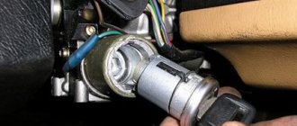
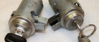
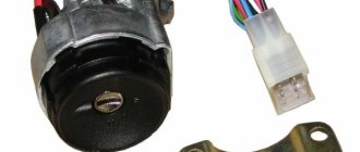
DocumentationDocumentation DiagramsConnection diagram for the ignition switch on the VAZ-2113, 2114 and 2115Pinout of the ignition switch for the VAZ-2113, 2114, 2115:
- comes +12V for the microphone of the sensor of the inserted key;
- the mass comes when the driver's door is open;
- +12V goes to the starter (pin 50);
- +12V goes out after turning on the ignition (pin 15);
- +12V goes out when the key is inserted to pin 5 of the BSK;
- comes +12V to illuminate the lock cylinder;
- +12V comes from the battery (pin 30);
- not used.
| Photo 1, pinout of the ignition switch of a VAZ 2114 | Photo 2, pinout of the ignition switch of the VAZ 2114 |
Date added: 07/14/2014 Author: Dmitriev Alexander
| None © AutoService | Online store, Ekaterinburg Unified information service: |
- * Why clean the throttle...
- * Priora. The AirBag light is on...
- * Computer engine diagnostics…
- * Nissan March error P0100 is on...
- * Mercedes C200 error P0171 is on, smell of gasoline...
- * Engine troubles, speed fluctuates, P0300 Gazelle...
- * The electric power steering (EUR) of the viburnum turns off, error C1044 is on...
- * Buggy firmware (programs) VAZ, GAZ, UAZ...
- * Volkswagen polo, error 00268 is on for valve N93, automatic transmission twitches...
- * Engine chip tuning, increasing engine power. Reviews, comments...
- * Battery case (charging case) for iPhone, Samsung. Review, tests, reviews….
- * Increased fuel consumption of the VAZ 2110, flooding the spark plugs....
- * Gazelle does not gain momentum, error P2138 is on....
- * VAZ 2114 is malfunctioning, the cylinders are not working, the ECU is burned out....
- * Ford Focus 2 does not respond to the gas pedal, burner error P2176....
- * Portable external battery for phone, tablet….
- * Installing a new instrument cluster 385.3801-10 on a Gazelle….
- * Toyota Camry stalls, the speed drops, it is difficult to start, the “CHECK” lamp is on....
DocumentationDocumentation Diagrams Diagram of the engine control system (ECM) VAZ-2110, 2111 and 2112
- – controller;
- – block of the ignition system harness to the ABS cabin group harness;
- – diagnostic block;
- – immobilizer warning sensor (APS);
- – immobilizer control unit (APS);
- - ignition coil;
- - spark plug;
- – nozzles;
- – electric fuel pump;
- – block of the ignition system harness to the electric fuel pump harness;
- – block of the fuel level sensor harness to the ignition system harness;
- – block of the ignition system harness to the injector harness;
- – block of the injector harness to the ignition system harness;
- - speed sensor;
- – idle speed regulator;
- – throttle position sensor;
- – coolant temperature sensor;
- – mass air flow sensor;
- – camshaft position sensor (phases);
- – oxygen sensor;
- – crankshaft position sensor;
- - knock sensor;
- – solenoid valve for purge the adsorber;
- – block of the ignition system harness to the instrument panel harness;
- – controller power supply fuse;
- – ignition relay;
- – ignition relay fuse;
- – fuse for the power supply circuit of the electric fuel pump;
- – electric fuel pump relay;
- – electric fan relay;
- – block of the ignition system harness to the air conditioner harness;
- – pads of the ignition system harness to the front harness;
- – electric fan of the cooling system;
- – block of the instrument panel harness to the ignition system harness;
- – ignition switch;
- – instrument cluster;
- – on-board control system unit;
- - starter relay;
- – mounting block;
A – to the “plus” terminal of the battery; B1, B2 – grounding points of the ignition system harness;
2115-3724026-11 – Ignition system harness;
- – block of the ignition coil wiring harness to the ignition system harness;
- – block of the ignition system harness to the ignition coil wiring harness;
- – ignition coils;
- – immobilizer warning sensor;
- – immobilizer control unit;
- - spark plug;
- – nozzles;
- – diagnostic block;
- – block of the ignition system harness to the ABS cabin group harness;
- – controller;
- – electric fuel pump;
- – block of the ignition system harness to the fuel level sensor harness;
- – block of the fuel level sensor harness to the ignition system harness;
- – block of the ignition system harness to the injector harness;
- – block of the injector harness to the ignition system harness;
- – block of the ignition system harness to the side door harness;
- - speed sensor;
- – idle speed regulator;
- – throttle position sensor;
- – coolant temperature sensor;
- – mass air flow sensor;
- – oil pressure warning lamp sensor;
- – camshaft position sensor (phases);
- – oxygen sensor;
- – crankshaft position sensor;
- - knock sensor;
- – solenoid valve for purge the adsorber;
- – coolant temperature indicator sensor;
- – block of the ignition system harness to the instrument panel harness;
- – block of the instrument panel harness to the ignition system harness;
- – ignition relay;
- – ignition relay fuse;
- – fuse for the power supply circuit of the electric fuel pump;
- – electric fuel pump relay;
- – electric fan relay;
- – controller power supply fuse;
- – block of the ignition system harness to the air conditioner connector;
- – instrument cluster;
- – ignition switch;
- – electric fan of the cooling system;
- – on-board control system unit;
- – additional starter relay;
- – contacts of the 8-terminal blocks of the instrument panel harness and the front harness;
- – contacts of the 21-terminal blocks of the instrument panel harness and the rear harness;
- - trip computer;
- – diagnostic connector;
A, E – to the “plus” terminal of the battery; B1 – grounding point of the ignition coil wiring harness; B2 – grounding point of the fuel level sensor harness; B3, B4 – grounding points of the ignition system harness; C – to the starter; D – to the driver’s door interior lamp switch;
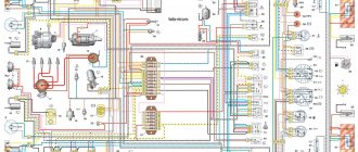
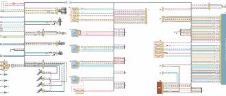
Diagram of the engine control system (ECM) Euro-3 Bosch 7.9.7+, M73 VAZ-2113, 2114 and 2115 (2111-1411020-30). Engine 1.6 liter 8 valve.
1 – controller; 2 – block of the ignition system harness to the ABS cabin group harness; 3 – diagnostic block; 4 – immobilizer warning sensor (APS); 5 – immobilizer control unit (APS); 6 – ignition coil; 7 – spark plugs; 8 – nozzles; 9 – electric fuel pump; 10 – block of the ignition system harness to the fuel level sensor harness; 11 – block of the fuel level sensor harness to the ignition system harness; 12 – block of the ignition system harness to the injector harness; 13 – injector harness block to the ignition system harness; 14 – speed sensor; 15 – idle speed regulator; 16 – throttle position sensor; 17 – coolant temperature sensor; 18 – mass air flow sensor; 19 – camshaft position sensor (phases); 20 – control oxygen sensor; 21 – crankshaft position sensor; 22 – knock sensor; 23 – solenoid valve for purge of the adsorber; 24 – rough road sensor; 25 – diagnostic oxygen sensor; 26 – block of the ignition system harness to the instrument panel harness; 27 – controller power supply fuse; 28 – ignition relay; 29 – ignition relay fuse; 30 – fuse for the electric fuel pump power supply circuit; 31 – electric fuel pump relay; 32 – electric fan relay; 33 – block of the ignition system harness to the air conditioner harness; 34 – pads of the ignition system harness to the front harness; 35 – electric fan of the cooling system; 36 – instrument panel harness connector to the ignition system harness; 37 – ignition switch; 38 – instrument cluster; 39 – on-board control system unit; 40 – starter relay; 41 – mounting block; A – to the “plus” terminal of the battery; B1 – grounding point of the fuel level sensor harness; B2, B3 – grounding points of the ignition system harness;
Replacing the ignition module of a VAZ 2114
If repairing the MZ VAZ 2114 is impractical or impossible, then the problem with the operation of the device can be solved by replacing it.
The equipment needs to be changed only when the battery is disconnected. Otherwise, there is a risk of short circuits and failure of other electrical appliances.
How to remove the ignition module of a VAZ 2114?
The dismantling procedure is performed as follows:
- First, the on-board network is de-energized; to do this, loosen the negative clamp on the battery with a wrench.
- Then a search for MH is performed in the engine compartment. You can find the device by four high-voltage wires that go from the spark plugs directly to the equipment. These cables are disconnected from the MH.
- Then the connector with conductors is disconnected from the device. It is necessary to disconnect the fixing fastener located on the ignition module housing.
- The MZ itself is secured to the bracket thanks to three nuts. You need to unscrew them using a key.
- After dismantling the fasteners, the device located on three studs is removed.
Connecting a new device
The equipment installation procedure is performed in reverse order; during installation, the following nuances must be taken into account:
- After installing the ignition module, you need to look at its surface. It is marked with numbers - 1, 2, 3 and 4. These symbols indicate the numbers of the cylinders to which the MZ should be connected.
- To properly connect the device, you need to look at the ends of the high-voltage cables. They are also marked with the same numbers. This is done in order to simplify the procedure for connecting the MH to the cables.
Connection diagram
The device must be connected in accordance with the diagram given in this section.
Connection diagram for MZ on VAZ 2114
How to check the device after connection?
Diagnostics of the operation of the new VAZ 2114 ignition module can only be performed using a special device - a high-voltage arrester.
You can find it in almost any auto store. Using the equipment, you can diagnose the module, as well as high-voltage cables, for the presence of a spark. To check, you need to connect the device to the device and use its operating instructions.
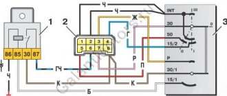
Connection diagram
The ignition module is part of the space under the hood, it’s easier to find it by the position of the high voltages, they go from the spark plugs straight to it.
Ignition coil diagram:
VAZ 2114 ignition coil diagram
This diagram is good to follow when you have to replace the ignition coil of a VAZ 2114. In principle, everything is transparent: from contacts with the controller (ECU) to high-voltage wires. The name of the circuit is often common under the name ignition coil pinout: the pinout is a visual representation of the functionality of the device's contacts, which are numbered according to their purpose.
Basically, the most necessary knowledge about what the pinout of the ignition coil is is carried by high-voltage wires (abbreviated as HF (contacts). Because it is through the HF contacts that, in fact, the ignition module is connected to the engine system.
It can be connected in two different ways: when the ignition system coil is removed and when it is directly in its place in the car engine.
If you are holding the module in front of you:
- Let us recall the diagram: the first and fourth contacts are on one winding, the second and third – on the other (they are numbered in the diagram!)
- Then, the lower explosive contact (left) goes to the first cylinder
- On the second - upper explosive contact (left)
- The third cylinder goes to the upper explosive contact (right)
- On the fourth – lower explosive contact (right)
If the module is plugged into the engine, then pinouting the explosive contacts will be more difficult, because the device stands at an angle (as if in a diamond):
- We throw the central lower contact onto the first cylinder
- On the second - left contact
- We put the upper contact on the third cylinder
- On the fourth - right contact
Of course, the first installation option is more convenient, especially since the explosive wires require increased care in the nature of the connection (mixed up and won’t start, in the worst case, the entire engine system is ruined). Speaking to the point, it is clear that the connection diagram for the VAZ 2114 ignition module is not complicated.
By the way, buying an ignition coil is not a cheap pleasure; the price of an ignition module for a VAZ 2114 ranges from seven hundred to a thousand rubles, depending on the location of your city on the map of our country (for more information about how much an ignition module for a VAZ 2114 costs, you can find out by calling a disassembly service or a spare parts store, the running part is almost always in stock).
What should I do if the problem remains after replacing the module?
If, after performing the repair, problems in the operation of the MH remain, then there is a possibility that the cause of the problem was not in the module. It is necessary to diagnose the remaining elements of the ignition system.
Spark plugs and ignition system
Features of checking spark plugs and other components:
- Before dismantling the devices, it is necessary to disconnect the ends of the high-voltage cables. Their condition is checked for damage. Defects in the tips often lead to malfunctions in the spark plugs. If there is damage, the wires are replaced. It is also necessary to assess the condition of the “high-voltage workers” themselves. They are not allowed to have any defects or damage to the insulation.
- After disconnecting the tips, the spark plugs are dismantled and a special spark plug wrench is used to unscrew them.
- After dismantling, the condition of the devices is assessed. The color of the parts must be brown; carbon deposits and soot on the electrodes are not allowed. If there are uncharacteristic marks, the devices are cleaned using a metal brush or fine-grained sandpaper. For a better effect, the electrodes of the candles can be heated on the stove.
- The condition of the gap between the part and the electrode element is checked. If it is too large, this indicates that the device is not working correctly. The spark plugs will need to be replaced.
Possible causes of failure
The weak point of the ignition coils and modules is the secondary winding, which generates a high voltage pulse. A coil break or breakdown may occur in it. The following factors lead to this phenomenon:
- use of low-quality or unsuitable candles;
- operation with non-functioning high voltage wires;
- frequent attempts to check the spark.
The high-voltage pulse arising in the secondary winding must be realized (spent). If this does not happen (if the integrity of a high voltage wire is broken, for example), a high-energy electrical pulse seeks an outlet. He will find it, with a high degree of probability, in the thin secondary winding.
Often, a module malfunction occurs when the integrity of poor-quality factory soldering of wires going to the switch elements is violated. This happens from vibration. Also, the cause of non-working coils can be a banal contact failure in the incoming connector. Another factor leading to a malfunction of the ignition unit is often moisture that gets on the device during washing or driving in unusual conditions.
Wiring diagram VAZ 2114 injector - rear harness
Wiring diagram for VAZ 2114 fwafva injector
- Mounting block;
- Rear window heating element;
- Rear window wiper motor;
- License plate light;
- License plate light;
- Left side turn signal;
- Side turn signal right;
- Individual lighting lamp;
- Interior lamp;
- Handbrake sensor;
- Left lamp;
- Right lamp;
- Additional brake signal;
- Interior lamp switch;
- Interior lamp switch;
- Interior lamp switch;
- Interior lamp switch;