Published: 10/20/2020
- Repair
- Methods for checking the ignition module of a VAZ 2114
- Repair
- How to disassemble the ignition module of a VAZ 2110
- Ignition module repair
- Version of the module on the 8-valve VAZ-2112
- We disassemble the design of the ignition module of a modern injector
- Checking module power
- Possible reasons for failure of the ignition module
- Diagram of the correct connection of wires to the ignition module
- Connection diagram
- VAZ 2115 ignition module, description and malfunctions
Repair
The design of the ignition module is quite complex: it includes one or more coils, a board, contacts and wires. Of all the above elements, only contact connections can be repaired; in some cases, replacement of parts (transistors, coils) is possible.
The module is dismantled and opened for repair purposes. For this you will need:
- Socket wrenches with heads 1, 13 and 17.
- Hexagon 5.
- Screwdriver.
- Soldering iron.
- Flux for aluminum.
- Stranded wire.
- Nail polish.
Repair of the ignition module is carried out in the following order:
- On the removed device, open the case by prying it off with a screwdriver.
- Remove the silicone film covering the board.
- All aluminum is removed from the explosive contacts.
- On the board, new wires are soldered in place of all the dismantled old ones. To do this, the surface of the collector is cleaned of deposits, after which the board is heated to 180°C (a characteristic smell will indicate when the desired temperature has been reached). During the soldering process, the ends of the wires are connected to the module.
- At the end of the operation, all contacts, the board and the module are covered with nail polish.
- The device is assembled in the reverse order, installed on the car and the engine is started. In case of normal operation, the ignition module is sealed tightly with sealant, while the wires are tucked inside the cavity so that they are not pinched at the edges by the plate.
If the device does not work, then a breakdown inside the module should be looked for more carefully. The transistor, electronic component may have failed, or there may be a break in the coil. Such a repair makes sense only if its price is significantly lower than the cost of a new part.
Methods for checking the ignition module of a VAZ 2114
There are several ways to find out if the module is working properly. Many car enthusiasts are wondering about checking the ignition module of the VAZ 2114, because there are several types of system for this model. Therefore, not each of them is suitable in structure and structure. The first of these options is quite effective and often used. First, you need to use another working module and try to start the engine with it, this will help you find out for sure whether the previous one is broken.
However, it is worth considering that there are different types of modules for a given type of car, so you need to use the one that is suitable. If the engine does not work properly with another module, then the old one needs to be replaced. If the problem is still in damaged wires, then there is a high risk of damaging another component. To prevent this situation, you need to inspect the wires for damage before checking. However, to do this, you need to know how to ring the ignition module to ensure that the wires are working properly and functioning properly.
Ignition module VAZ 2114
Using a Multimeter
All you need to do is use a multimeter that is set to voltmeter mode. After which you need to disconnect the ignition module and coil. Next, you need to carry out some manipulations with the contacts called “A” and the engine ground. Try starting the engine and look at the multimeter readings. They should not exceed 12 V. Carry out similar actions with the second contact. Other indicators besides those indicated may be the result of a malfunction or breakage of high-voltage wires. However, in some cases, the current may not flow or flow, but in small quantities because the fuse has blown.
It is worth noting that this vehicle model has three fuses that trigger the spark plugs. Therefore, to exclude this option, it is necessary to check the proper functioning of the fuses. After all, the proper operation of the engine depends on each component of the whole mechanism. However, in order to check the ignition module with a multimeter, you need to make sure that the wires through which high voltage enters the module do not contain damage or cracks. After all, this entails damage to the entire diagnostic process.
Diagnostic algorithm
Nevertheless, before checking the ignition module on the VAZ-2114, it is worth familiarizing yourself with the algorithm of actions that need to be performed during further diagnostics. This algorithm includes the following items:
- The high-voltage circuit checks the ignition module for breaks;
- inspection and testing is carried out by tugging and tapping (a similar method is most often used by car enthusiasts to check the serviceability of parts and components of the mechanism).
In the case of the first point, take a multimeter configured to determine resistance. Since the connections in the ignition coil are parallel, the resistance that exists between them must be at a certain level. Otherwise, when the readings are different, it may mean that a break has occurred. In this situation, the model cannot be repaired and must be replaced. For the second point, such actions are the norm, despite the fact that it sounds a little not serious.
However, after these procedures, there is a possibility that the component will begin to function, albeit for a short period of time. Still, after this you need to go to a specialized vehicle store and buy a new component.
To avoid such situations, it is necessary to do regular inspection of your mobile vehicle. Also carry out checks to ensure that important engine parts, such as the ignition module, are in good working order. After all, it is thanks to him that your car starts and drives stably. Most often, specialists working in auto shops can advise clients on issues that interest them, as well as provide recommendations in the selection of parts.
Reel design and operation
The modern bobbin is a simplified version of the Ruhmkorff induction coil. It was named after the German-born inventor Heinrich Ruhmkorff, who was the first to patent a device in 1851 that converts low-voltage direct voltage into high-alternating voltage.
To understand the principle of operation, you need to know the structure of the ignition coil and the basics of radio electronics.
This is a traditional, common VAZ ignition coil, used for a long time and on many other cars. In fact, this is a pulse high-voltage transformer. On a core designed to enhance the magnetic field, a secondary winding is wound with a thin wire; it can contain up to thirty thousand turns of wire.
On top of the secondary winding is a primary winding made of thicker wire and with fewer turns (100-300).
The windings at one end are connected to each other, the second end of the primary is connected to the battery, the secondary winding with its free end is connected to the voltage distributor. The common point of the coil winding is connected to the voltage switch. This entire structure is covered by a protective housing.
A direct current flows through the “primary” in the initial state. When a spark needs to be formed, the circuit is broken by a switch or distributor. This leads to the formation of high voltage in the secondary winding. Voltage is supplied to the spark plug of the desired cylinder, where a spark is formed, causing combustion of the fuel mixture. High-voltage wires were used to connect the spark plugs to the distributor.
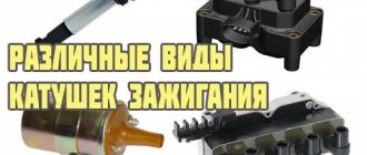
The single terminal design is not the only one possible; there are other options.
- Double spark. The dual system is used for cylinders that operate in the same phase. Let's assume that compression occurs in the first cylinder and a spark is needed for ignition, and in the fourth cylinder there is a purge phase and an idle spark is formed there.
- Three-spark. The principle of operation is the same as that of a two-terminal one, only similar ones are used on 6-cylinder engines.
- Individual. Each spark plug is equipped with its own ignition coil. In this case, the windings are swapped - the primary is located under the secondary.
Repair
So, for the VAZ 2110 the most common problem is the disappearance of voltage on cylinders 2 and 3. After some time, the engine starts working normally again if you press the rear plate of the module.
You should not put up with such a situation; it is better to immediately check the functionality of the unit, restore or replace it completely.
Removing the module
The procedure is quite simple.
- Disconnect the negative cable from the battery.
- Remove the plastic cover that covers the motor.
- Remove the wires from the spark plugs.
- Disconnect the wires from the ignition module. Their numbering is indicated on special white rings. And the cylinder number is indicated on the ignition module housing.
- Disconnect the connector from the ignition module.
- Using a 10mm socket, unscrew the three nuts that hold the block we are looking for.
- Carefully remove it, after which you can begin further work.
Now let's move directly to working with the module:
- Open the aluminum plate on the ignition module. A flathead screwdriver is useful for this.
- Inside you will find a small printed circuit board with electronic components. It is covered with a transparent layer of silicone, which will have to be removed.
- There are also wires that connect the board to the connector contacts. They are made of aluminum, so they can tear quickly.
- Tear off all the wires from the contacts, don’t be afraid. Others will be installed in their place. By the way, experts recommend using stranded wires used in computer mice.
- The ignition module circuit includes two switches and two powerful transresistors. If you decide to change these elements, you need to know that the switches are manufactured by SGS-THOMSON (model L497D1), and the transistors are of the BU931 type.
- The contacts are made of aluminum, so you will need a special flux to work with this metal.
- We solder the wiring to the board. It is more difficult to solder to the transistor collectors, since they are covered with a special material, the soldering of which is problematic. Therefore, try to hide the top coating from the element as carefully as possible. To prevent the soldering iron from transferring all the heat to the plate, place it on the stove and heat it to 180 degrees Celsius.
- Solder the wires to the contacts on the module so that they are as short as possible.
- Cover the areas where you soldered with varnish. Regular nail polish borrowed from your wife will do.
- Check if the ignition module is working.
- If everything is fine, coat the inner surface with a special autosealant, then reassemble in the reverse order.
- Upon completion of assembly, the wiring should be positioned fairly freely. Make sure that they are not compressed inside the box and that the integrity of the connections is not broken.
Carrying out a similar repair of the ignition module on a VAZ 2110 with your own hands will not be difficult.
But be careful, act carefully and consistently
Pay special attention to the soldering process
But keep in mind that we have addressed the problem of bad contacts. She is not the only one for the “ten”. You may need to pinout the ignition module on the VAZ 2110. For this, it is better to contact specialists.
If the cause of the malfunction lies elsewhere, then there is a high probability that it is better to simply replace the VAZ 2110 8-valve ignition module with a new one. The search may drag on without yielding results. Replacing the element will completely solve the current problem.
Possible causes of failure
The weak point of the ignition coils and modules is the secondary winding, which generates a high voltage pulse. A coil break or breakdown may occur in it. The following factors lead to this phenomenon:
- use of low-quality or unsuitable candles;
- operation with non-functioning high voltage wires;
- frequent attempts to check the spark.
The high-voltage pulse arising in the secondary winding must be realized (spent). If this does not happen (if the integrity of a high voltage wire is broken, for example), a high-energy electrical pulse seeks an outlet. He will find it, with a high degree of probability, in the thin secondary winding.
Often, a module malfunction occurs when the integrity of poor-quality factory soldering of wires going to the switch elements is violated. This happens from vibration. Also, the cause of non-working coils can be a banal contact failure in the incoming connector. Another factor leading to a malfunction of the ignition unit is often moisture that gets on the device during washing or driving in unusual conditions.
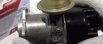
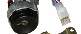
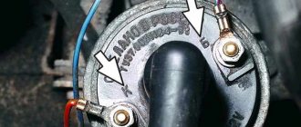
WHERE TO FIND THIS MODULE
It is hard to believe that the driver who undertakes to check or repair this device does not know where it is located. Well, for those who don’t know, we’ll tell you. It’s easy to find it, find at least one high voltage wire, and walk your hand along it from the spark plug to the plastic case that belongs to the module.
From the picture its location becomes clearer.
How to disassemble the ignition module of a VAZ 2110
Many car owners are faced with the problem of their car not starting. If it suddenly turns out that high voltage has disappeared on the cylinders (either only on one, or on several at once), or the warning lamp does not light up, there is no spark, then the engine will not work. The ignition module may have failed. It's not always worth rushing to stores to look for something new.
Those who own a VAZ-2110 car are offered an alternative - repairing the ignition module themselves. The main thing is to have basic knowledge of auto electricians and the ability to understand circuits and contacts. It’s also a good idea to know how to use a digital multimeter in your work.
In order to disassemble the ignition module, you will also need knowledge of its components. This is a pair of ignition coils designed to excite high-voltage pulses, and a two-channel switch. Basically, high-frequency pulses can disappear in the 2nd and 3rd cylinders. You will have to start by removing the ignition module. The high-voltage wires are disconnected, then the VAZ-2110 ignition module itself is removed.
Unscrew the bolts
We get the board
Reassembling the sensor in reverse order
The essence of the repair is as follows:
To open the aluminum plate you will need a straight screwdriver. Looking at the inside of the module, it may seem that everything is very complicated. Attention should be paid to the printed circuit board, which is coated with transparent silicone. The sealant is removed. To make the wires with which the board is connected to the contacts of the connectors and coils, too soft aluminum is used, so they become unusable. Such wires are torn off and thrown away. What should I put in place? You will need a computer mouse, which will have to be disassembled. It only requires stranded wires. The ignition module circuit includes two L497D1 switches, which are also manufactured by two fairly powerful transistors. The contacts are aluminum, so for soldering you will need a special flux for aluminum. First, the wires are soldered to the board itself. During manufacturing, the collectors are coated on top with a special metal that cannot be soldered. Therefore, before soldering the wires, the coating is removed from the metal. Then the plate is placed on the stove and heated to one hundred and eighty degrees, the heat will be distributed throughout the plate
This is important so that when the soldering iron comes into contact with the plate, the heat does not dissipate from it. Now you can proceed directly to soldering the wires to the module contacts. Try to make the wires as short as possible.
Next, take a varnish (the varnish you use to paint your nails will also work), and use it to insulate the joints. Next, you need to check the ignition module. It must be functional. And the final touch: the inner surface is coated with autosealant, after which the assembly is completed. The wires should be positioned freely and not be pinched.
The work is not that difficult, and can be done by anyone who can work with a soldering iron and have basic knowledge of electronics.
If after repair it turns out that the cause of the malfunction was different, then this reason needs to be found, or go to the store for a new module.
Ignition module repair
If the ignition module does not work, you can try to rehabilitate it:
- Take 10, 13 and 17 end keys, a 5 hex key, a regular screwdriver, a soldering iron, aluminum flux, nail polish, and stranded wires.
- Most often, the connection in the ignition system deteriorates - those same contacts.
- We turn the key in the ignition, start it, move the contacts, and get a comprehensive answer in the absence of their quality connection.
- Now we turn off the engine and remove the ignition module out.
- You need to open it, pry up its body with a screwdriver.
- Inside the board is covered with silicone film - remove it.
- We remove all aluminum from the explosive contacts.
- Now comes the hard part: we need to solder new wires to the plan from where we just removed the old ones.
- First, you need to clean the surface of the collector from plaque, then put the board on the stove and heat it to 200 degrees (approximately by eye, of course), it will start to smell a little when it reaches the desired temperature and soldering on it will become much easier.
- Now, actually, we solder: we connect the ends of the wires to the module.
- We cover all the contacts of the wires with the module and the board with nail polish.
- Now you need to put everything back together, put the ignition device in place and start the engine. Only after this, when you are convinced that everything is working properly, can you take the sealant and seal it tightly.
- Individual elements that have failed. They cannot be repaired, they are only for replacement. Fortunately, the price for them is adequate: a switch is within 200 rubles, a transistor is from 200 to 300 rubles.
A very important point: in common parlance, as here, the ignition coil and the ignition module are synonyms. But in terms of technical design, no. For fourteenths with different engine sizes, different spare parts are installed: for 1.5-liter Samaras of the old generation, it is the ignition module, and for 1.5 and 1.6 liters of the new generation Samaras, it is the ignition coil. The switch of the new type of machines is hidden in the electronic control unit, it turns out that the module was broken, and they began to call it by the name of its main part - the coil. Be careful when choosing a spare. parts from disassembly: do not confuse them, given this fact.
If we talk about service, the price is not worth the cost. It’s easier to figure everything out yourself, even more so. That there are a lot of resources where they can give you advice and help. The main thing is to remember the layout of the high-voltage wires and their good contact. It happens that incorrectly connected wires contribute to improper combustion, a spark hits the relay. And the ignition module completely burns out.
HOW TO CHECK THE SYSTEM FOR OPERATION
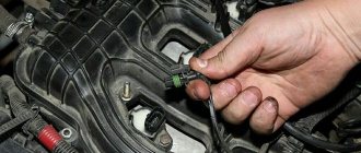
In any case, the check begins with the candles. To do this, they need to be removed from their nests. This is also easy to do. Remove the tips of the high-voltage wires from them and, using a wrench for turning out the spark plugs, remove them from their places.
Next comes their inspection, cleaning and testing. They should have a working brown color, with no soot or soot. If their presence is observed, then there may be wear on the pistons and rings. In any case, the spark plugs are cleaned, checked and, if necessary, the gap between the electrodes is adjusted. After this, you can check their performance. For these purposes, there are special probes. “Craftsmen” manage to make such products themselves from a piezo lighter. If nothing like this is available, then check it on the engine. It’s good if there is a car nearby with a known good starting system. This will make it possible to make an accurate diagnosis for candles. If they are in good condition, the search continues further.
Many publications recommend checking for the presence of high voltage voltage at the terminals of the device. Doing this in a garage is problematic due to the lack of a special measuring device. A conventional tester is used here, since it cannot measure several tens of kilovolts of high voltage. If you have experience as a radio amateur, you can assemble a voltage divider.
Checking for the presence of high voltage is dangerous due to a possible sensitive electric shock, so we will touch on other methods. Let's talk about how you can determine ignition coil malfunctions and check this system:
- The simplest method is to replace the unit with a working device. It is not always possible, since not all drivers carry this device with them in reserve;
- They also advise, which has been tested many times, to move the device or knock on it while the motor is running. If changes are noticeable, they indicate poor contact inside the device. Sometimes it's fixable;
- Check with a tester or multimeter in resistance measurement mode. The resistance of the paired terminals of the coils, 1 and 4, as well as 2 and 3, is measured. It should be identical for both windings and equal to approximately 5.4 kOhm.
Version of the module on the 8-valve VAZ-2112
Two 8-valve engines of different volumes were installed on the twelve-wheeler - 1.5 and 1.6 liters. The ignition modules for these engines are different. The one and a half liter engine has a module with article number 2112-3705010, and the 1600 cc engine is equipped with a module 2111-3705010. A module for a 1.5 liter engine costs about 1500-2100, and the second one is 500 rubles cheaper.
Module structure
It consists of two ignition coils and two high-voltage switch switches. The coils are designed to create high-voltage pulses.
In essence, it is a simple transformer that has two windings: a primary winding, with an induction voltage of approximately five hundred Volts, and a secondary winding, with an inductive voltage of at least twenty kiloVolts. Everything is placed in one housing with one connector for signal wires and four for high-voltage.
Structure of the ignition coil module of the VAZ 2112
The operation of the ignition module is based on the “idle spark principle”. The module is capable of distributing a spark in pairs: to the first and fourth, second and third cylinders when transmitting pulses from the electronic control unit.
Video on repairing KZ VAZ
Often, when the ignition module breaks down, the car owner immediately runs to the store and buys a new one. But, for the VAZ-2112 there is an alternative method - repair. Of course, without proper knowledge in auto electrics, it will be difficult to understand all the circuits and communications. This article will tell you in the most accessible way how to repair the ignition module with your own hands.
We disassemble the design of the ignition module of a modern injector
As an example, consider a similar device used on injection VAZ cars. The module operates according to the good old principle: 12 volt power is supplied to the input, and a high voltage is generated at the output contacts for sparking.
The control is electronic, but the operating principles differ from a simple distributorless ignition system:
- All components are located in one housing. On the one hand, this is convenient - fewer wires and contacts - lower probability of breakdown. On the other hand, if the ignition module burns out, it must be repaired; simply replacing the failed element will not work.
- The device is compact and can be conveniently placed in the engine compartment.
- The ignition module is powered at low voltage, which increases the reliability of the device.
- The cost of the finished device is low.
- This ignition module has two coils. This contributes to the survivability of the device - each transformer is loaded twice as much.
The secret of the module’s operation is as follows: it uses not four, but two coils for 4 cylinders. Masters of the old school call this device a two-spark bobbin. Alternating connection of each coil produces two sparks: working and idle. Due to proper distribution among the spark plugs, the idle spark is ignited at the moment when there is no air-fuel mixture in the corresponding cylinder.
The signal for sparking is given by the switch (acting as an electronic distributor). Before checking the ignition module, you need to make sure that control pulses are coming to the contact blocks from the switch.
This block is responsible for the so-called ignition advance, that is, it generates a signal at the right moment. The control pulse about the position of the crankshaft is issued by the Hall sensor, which also synchronizes the operation of the entire system.
The principle of operation of the ignition coil.
The module is a kind of connecting link: from the electronic control unit, which controls its working process, a certain signal is sent to the winding (in the form of charged pulses); then, the module produces high voltage, which is transmitted to the spark plugs through high voltages. This action allows the candles to produce the necessary spark to start the internal combustion of the air-fuel mixture in the chamber space.
The new generation VAZs, including the fourteenth, are equipped with an ignition system coil; it is not included in the general module, since its other important part - the switch - is located in the electronic unit. If you take the old-style VAZs, including the fourteenth with a 1.5-liter engine, then they have an ignition system module: two coils and two switches in a single housing. Two coils are connected to the cylinders by high-voltage wires (each for two cylinders: one for the 1st and 4th, the second for the 2nd and 3rd).
Signs of a faulty ignition coil:
- When accelerating you feel a failure,
- Power drops
- At idle the engine behaves unstable,
- The engine has problems (cylinders fail).
Before deciding what to do with a failed ignition coil, you need to check it. No special skill is required, just know what a multimeter is and how to hold it in your hands. Depending on the test result, you should make a decision: replace or repair.
In principle, the fundamental malfunction of the ignition coil is always the lack of normal contact. Maybe the mass has broken, maybe the contacts are stuck or oxidized. A small deposit of dust can put an entire cylinder out of working order, not to mention a modest module.
Along with possible module malfunctions, it is recommended to check all sensors - from mass air flow to DS - there is a serious possibility of failure of one of them.
Checking module power
Before testing the performance of the coils, you should make sure that a possible breakdown is not caused by a loss of power to the device. First, you need to try to simply restore contact by moving it several times or disconnecting/connecting the block of wires included in the connector. If such manipulation does not lead to improved engine performance, a tester (multimeter) is used to determine the quality of incoming pulses.
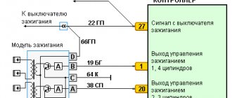
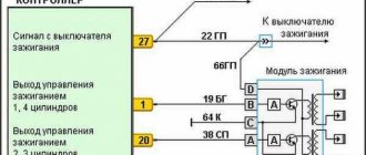
The block of wires is removed from the connector. On the block, each terminal (A, B, C, D) has a corresponding socket. Testing with the engine running is done as follows.
- The first contact of the tester is in socket D, the second is to ground. The multimeter switch position is 20 volts. If there is power, the tester shows 12 volts.
- The first contact is in socket C, the second is ground. Switch on ohmmeter (20 Ohm). Normally it shows less than 1 ohm, that is, the mass is normal.
- The first contact is in socket B, the second is ground. 20 volt switch. The norm is not less than 0.3 volts. If this is so, it means that a normal pulse is coming from the Hall sensor to position B.
- Contact A is checked similarly to the previous one.
If such a check shows the norm, you need to test the module. If not, look for the cause in the electrical circuit to the coil.
What's the difference between contactors and starters?
Both contactors and starters are designed to close/open contacts in electrical circuits, usually power ones. Both devices are assembled on the basis of an electromagnet and can operate in DC and AC circuits of different powers - from 10 V to 440 V DC and up to 600 V AC. Have:
- a certain number of working (power) contacts through which voltage is supplied to the connected load;
- a number of auxiliary contacts - for organizing signal circuits.
So what's the difference? What is the difference between contactors and starters? First of all, they differ in the degree of protection. Contactors have powerful arc extinguishing chambers. This leads to two other differences: due to the presence of arc arresters, contactors are large in size and weight, and are also used in circuits with high currents. For low currents - up to 10 A - only starters are produced. By the way, they are not produced for high currents.
There is one more design feature: the starters are produced in a plastic case, with only the contact pads exposed outside. Contactors, in most cases, do not have a housing, therefore they must be installed in protective housings or boxes that will protect against accidental contact with live parts, as well as from rain and dust.
In addition, there is some difference in purpose. The starters are designed to start asynchronous three-phase motors. Therefore, they have three pairs of power contacts - for connecting three phases, and one auxiliary one, through which power continues to flow to operate the engine after the “start” button is released. But since a similar operating algorithm is suitable for many devices, a wide variety of devices are connected through them - lighting circuits, various devices and devices.
Possible reasons for failure of the ignition module
Before repairing the main part in, you need to understand the nature of the problem. To do this, the consumer must be aware of the signs of a malfunction, as well as the causes of the breakdown.
The main reasons for device failure
Causes of problems:
- The ignition system uses spark plugs that do not match the vehicle parameters. They may not have the gap specified by the manufacturer. Also, the spark plugs themselves may not be working or dirty; this can be determined by visual diagnostics. If there are traces of carbon deposits on the devices, they must be removed.
- Malfunctions in the operation of the MH can arise as a result of frequent spark checks. At the time of diagnosis, a high load is placed on the device. If it appears frequently, it will lead to equipment failure or incorrect operation.
- in the VAZ 2114 it functions with the high-voltage cables disconnected. This also leads to device failure. The products themselves may be damaged, which affects the functioning of the engine as a whole.
- The device operates under severe vibration conditions. Their impact may be due to poor quality fixation of the module in the seat. As a result of vibrations, the factory soldering inside the equipment structure is damaged. This leads to its incorrect operation.
- The contact inside the plug with the low-voltage cables is broken.
- Initial use of a defective device or module with poor build quality. This factory defect can only be eliminated by replacing the mechanism; repairing the equipment is pointless.
- Moisture getting inside the case. This problem is unlikely, but exposure of the device to liquid may cause it to short out and break.
Signs of coil malfunction
The main symptoms of a malfunction in the VAZ 2114 ignition module:
- Difficulties arise when trying to start the engine. Starting the car engine may be difficult due to the fact that there is no spark on a spark plug or several.
- When idling or parking with the internal combustion engine running, the speed of the power unit floats. Their change is not associated with pressing the gas pedal and other third-party factors. This happens randomly.
- There are dips in the power of the car's engine. This is especially felt when driving uphill or sharp acceleration. Problems can also occur when driving on a flat road.
- Several cylinders stopped working. Usually these devices operate in pairs, so elements 1-4 or 2-3 could fail. Non-working cylinders may be indicated by “triple movement” of the engine.
- A “Check Engine” warning light appeared on the dashboard.
If the ignition module malfunctions, problems will appear not only in engine operation, but also when starting it.
The “Simple Opinion” channel, using the Lada Priora car as an example, spoke in detail about the symptoms that appear in the operation of the ignition modules.
Diagram of the correct connection of wires to the ignition module
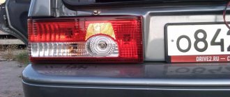
If, after checking the wires, you are convinced that they are all tightly connected to the spark plugs, let’s check that the wires themselves are connected correctly. Of course, if no one has climbed into the engine before you, then there is no point in checking. If there was traction and it disappeared, the reason could be both in the coil and in the wires themselves - they could be pierced. But in any case, let's check that the connection is correct. The ignition module shows the numbering of the cylinders to which the wires fit.
- 1 cylinder – central lower outlet
- Cylinder 2 – left output
- Cylinder 3 – top outlet
- 4 cylinder – right output
The diagram is shown for a coil installed on a vehicle.
If after checking no problems are identified, you should consider replacing the coil or wires. It is advisable to change both.
The cost of PVN, depending on the manufacturer, ranges from 300 to 600 rubles per set. The most popular manufacturers:
The cost of an ignition coil is from 1300 to 2500 rubles. Modules from the following companies can be found in stores:
When choosing a module, you should pay attention not only to the manufacturer, but also to the coil itself; it comes in old and new designs. Therefore, it is better to dismantle yours and bring it to the store.
Connection diagram
The ignition module is part of the space under the hood, it’s easier to find it by the position of the high voltages, they go from the spark plugs straight to it.
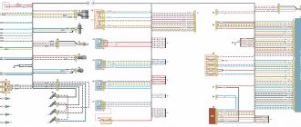
Ignition coil diagram:
VAZ 2114 ignition coil diagram
This diagram is good to follow when you have to replace the ignition coil of a VAZ 2114. In principle, everything is transparent: from contacts with the controller (ECU) to high-voltage wires. The name of the circuit is often common under the name ignition coil pinout: the pinout is a visual representation of the functionality of the device's contacts, which are numbered according to their purpose.
It can be connected in two different ways: when the ignition system coil is removed and when it is directly in its place in the car engine.
If you are holding the module in front of you:
- Let us recall the diagram: the first and fourth contacts are on one winding, the second and third – on the other (they are numbered in the diagram!)
- Then, the lower explosive contact (left) goes to the first cylinder
- On the second - upper explosive contact (left)
- The third cylinder goes to the upper explosive contact (right)
- On the fourth – lower explosive contact (right)
If the module is plugged into the engine, then pinouting the explosive contacts will be more difficult, because the device stands at an angle (as if in a diamond):
- We throw the central lower contact onto the first cylinder
- On the second - left contact
- We put the upper contact on the third cylinder
- On the fourth - right contact
Of course, the first installation option is more convenient, especially since the explosive wires require increased care in the nature of the connection (mixed up and won’t start, in the worst case, the entire engine system is ruined). Speaking to the point, it is clear that the connection diagram for the VAZ 2114 ignition module is not complicated.
By the way, buying an ignition coil is not a cheap pleasure; the price of an ignition module for a VAZ 2114 ranges from seven hundred to a thousand rubles, depending on the location of your city on the map of our country (for more information about how much an ignition module for a VAZ 2114 costs, you can find out by calling a disassembly service or a spare parts store, the running part is almost always in stock).
Communities › VAZ: Repair and Modification › Forum › VAZ 2110, injector, 8 cells, won’t start, no spark
Good day to all. Yesterday my friend’s car stopped starting; as it turned out, there was no spark at the spark plugs. A new Ignition Module, new explosive wires, and a new DPKV were purchased at the store. ECU January 5,1,1 was replaced with exactly the same one that was known to work. But the engine still doesn't want to work. So far I have found out that on the chip going from the ECU to the Ignition Module, on the last contact (D) there is 12 volts when the ignition is turned on, and on the penultimate one there is ground. So, as I understand, the control signals for sparking go through the 1st and 2nd connectors (A and B). But how can you find out whether these signals are reaching the coil? I connected a low-power 5w light bulb to these connectors, that is, one end to the ground of the car, and put the other end into connectors A and B and turned the starter, the light did not light up. Maybe a very weak current is generated there? Or do you need to dig in the direction of the break in both wires (which is unlikely)?