Hi all! As I wrote a long time ago, I wanted to improve the power supply to the ignition module. This idea came after I accidentally came across an article by user mcsystem, for which I thank him. An additional fuse box was even installed, but another problem arose. My character does not allow me to get involved in the factory wiring; I like it when everything can be returned to stock without major problems. Therefore, I wanted to find the ignition module connectors and make a removable system. The connector that is inserted into the module was found in the store without any problems, but the mating part is more difficult to find. It was decided to rip the connector out of the dead module. But finding a dead module in my city turned out to be problematic. And paying 2 kilo rubles for a new one is stupid because of the connector. That's why the matter stopped.
But the world is not without good people, and exclusive33rus sent me a dead module, for which I thank him very much! At the factory I took two wires with a cross-section of four squares, and real four squares, and not those funny wires that are sold in the store. Well, at the same time, two tips, with holes for 6 and 8 mm, since I still didn’t know which one I would put.
I tore the connector out of the module, measured the required length of wires and began soldering. And here’s a surprise - the metal that connects everything in the module is not soldered with anything! The metal is very shiny, like lead, and brittle to bend like aluminum. I was upset, but there was nothing to do, I had to think further. And then the OBD-II diagnostic KKL cord caught my eye, and I saw that the pins were the same! I disassembled it, found unused pins, heated them with a soldering iron and pulled them out. I pulled out solderless pins of unknown metal from the connector and melted the pins from the cord. I soldered it and decided to fill the soldering area with supermoment and soda. It was with great grief that I found superglue at home, but, as they say, it wasn’t diarrhea—it was scrofula, and there was no soda at home. It seems like such a thing that everyone has had for years and practically never used, but I don’t have it. It was late, the shops were already closed, there was no way to buy anything. And then I remember that on the balcony there is soda ash, which I used to make printed circuit boards using the photoresist method. I try it with superglue - everything is great! I fill the connector, and am faced with the second problem - the wire did not fit into the connector, so about five centimeters to the connector I had to slightly reduce the cross-section, from four squares it dropped to about 2.5, but I thoroughly tinned everything, so the losses will be minimal. I put everything in the corrugation and leave the wiring until daylight; it’s not very convenient to install in the dark.
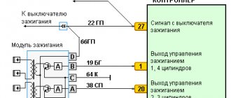
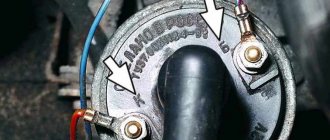
As you can see, there is a relay in the circuit. Those who understand electrics, I think, understood immediately, but for the rest I’ll explain what I can do. So, there are four wires going to the module, two signal wires, through which the ECU gives the command to give a spark to the cylinders (1-4 and 2-3, respectively), and two 12 volt power supply. So the signal signals go directly from connector to connector, but the module’s power now goes to the relay, through which +12 volts goes directly from the battery with a thick wire.
Ignition coil device
It is known that on 8-valve engines an ignition module was used (module repair, diagnostics) with two channels and coils that are capable of transmitting a spark to a pair of spark plugs at once. However, on a 16-valve engine, the coils became individual for each spark plug.
Prices and articles
The ignition coil from the Russian manufacturer SOATE for the VAZ-2112 has article number 2112-3705010-12 and costs around 1,000 rubles . Analogs from Bosch can cost twice as much, but the quality of these parts is much higher. In any case, the choice is always yours.
Purpose and principle of operation
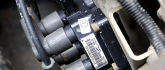
The ignition module of a VAZ-2114 car with an injection 8-valve power unit is located directly opposite the engine block on the spark plug side. This arrangement is most effective for supplying high-voltage wires to the spark plugs. The device is mounted on the wall of the engine compartment. This position was not chosen by chance. This way the MH interacts less with vibrating parts of the car.
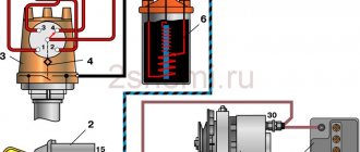
The device that comes with the described car model is of the block type. One housing contains 2 inductors and 2 discharge voltage regulators. The device operates according to the following principle:
- A pulse signal passes from the crankshaft position controller to the on-board computer.
- The signal is confirmed by a pulse signal from the Hall sensor of the ignition system.
- Both signals are calculated in the on-board computer and transmitted as current to the module.
- The module converts 12 volt voltage into high current.
- From the coil, the voltage is supplied to the spark gap, which forms a pulse voltage.
- The voltage passes through the high voltage wire of cylinders 1 and 4 to the spark plug.
- The spark plug is discharged by a spark, igniting the fuel in the cylinder.
- During the discharge, spark plugs 2–3 also receive voltage, but its power is adjusted by the spark gap.
All components are made of high-strength plastic with an aluminum plate for mounting to the engine. Additionally, both coils are filled with insulating solution. On the body of the device there are only 4 contact sockets for high-voltage wires and an electrical power socket.
Subject to all operating rules, the ignition module is a very reliable electronic device, but it is quite fragile. If the electrical circuit has a number of damages and is often subject to short circuits, then the coils or arresters fail.
Any malfunction of the MH leads to interruptions in engine operation. The following will describe the main symptoms of a malfunction of this device.
The process of checking all ignition coils on a VAZ-2112
The VAZ-2112 engine with 16 valves uses individual Bosch ignition coils and in order to check them, the following procedure must be followed:
- First of all, we remove each coil from its landing well.
- Then we turn off the power supply and remove them all together as an assembly.
- First of all, we pay attention to its external condition, the absence of cracks and various breaks.
- The same applies to the spring located inside the coil, look at its position, it should be exactly in the center.
Despite the fact that many people on the Internet talk about the impossibility of checking a coil with their own hands, it is possible to check it only by knowing their initial values, which are measured in ohms .
- In order not to make false measurements, first of all we check the internal resistance of the wires and the multimeter itself . To do this, switch the device to the OM position and connect the probes to each other. What value the multimeter gives is its internal resistance. The value can range from 0.0 to 0.3 ohm.
- First of all, we “ring” the primary winding, which is located on the first and third contacts; when connecting, the polarity does not matter.
- Depending on the presence of error readings and coil readings, we add up the final indicators. For example, if the internal resistance is 0.2 ohms and the coil value is 0.7 ohms, therefore the correct value would be 0.5 ohms. Which is the norm.
- We continue diagnostics with each of the coils.
- If it happens that there are no indications, then we once again check the quality of the connections and the correctness of the connection. If the readings are still zero, then the primary winding on this coil is faulty.
How does a reel work?
If we consider the general principle of operation of the ignition coil and its design, a high-voltage pulse step-up transformer has a primary winding and a secondary winding.
The primary winding with several turns of thick wire is designed for low voltage. The secondary winding of the coil has many more turns of thin wire. Due to electromagnetic induction on the secondary winding, it is possible to create a high output voltage.
Next, the voltage is transmitted through high-voltage wires to the breaker-distributor (distributor) in a car with battery ignition. As for models with transistor or electronic ignition, in this case the voltage is supplied to the ignition control unit, after which it is supplied to the spark plugs.
We also note that a resistor may be present in the primary winding of some coils. In short, this is a steel alloy spiral with a high resistance coefficient. When the current on the winding is high, then the resistance increases, which allows automatic regulation.
By the way, when starting a motor with a dead battery, you should forcefully short-circuit such a resistor (you can use a screwdriver or wire). This will allow the engine to start easier and faster.
- Another thing that can be highlighted is that there are several types of ignition coils, although the design of the ignition coil is often not very different. The first type is a general coil, which generates high-voltage voltage. Installed in front of the distributor-distributor or electronic ignition control unit.
The second type is an individual cylinder, which operates on only one cylinder. This solution is placed in front of the spark plugs and is considered more reliable due to the fact that if one coil fails, the engine will still be able to operate. We also note that on different cars, ignition coils have different characteristics, which depends on the type of vehicle, class of car, engine power, etc.
conclusions
Thanks to this simple procedure, you can quickly check the performance of the ignition coils on a VAZ-2112 with your own hands, without resorting to the help of special diagnostic stations and specialists.
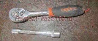
You will need a 5mm hex key.
If the ignition coil is removed to gain access to the coolant drain hole from the cylinder block, then it is necessary to remove the coil along with the bracket (see “Replacing the ignition module on engines 2111 and 2112”)
| The problem of floating engine speeds, sluggish acceleration with jerks and increased fuel consumption are familiar to almost every owner of a VAZ car. One of the reasons for these ailments lies in the ignition system. Let's consider the modification of individual ignition coils (ICC), which will help cope with unstable sparking. |
Ignition module repair
If the ignition module does not work, you can try to rehabilitate it:
- Take 10, 13 and 17 end keys, a 5 hex key, a regular screwdriver, a soldering iron, aluminum flux, nail polish, and stranded wires.
- Most often, the connection in the ignition system deteriorates - those same contacts.
- We turn the key in the ignition, start it, move the contacts, and get a comprehensive answer in the absence of their quality connection.
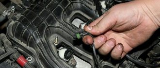
- Now we turn off the engine and remove the ignition module out.
- You need to open it, pry up its body with a screwdriver.
- Inside the board is covered with silicone film - remove it.
- We remove all aluminum from the explosive contacts.
- Now comes the hard part: we need to solder new wires to the plan from where we just removed the old ones.
- First, you need to clean the surface of the collector from plaque, then put the board on the stove and heat it to 200 degrees (approximately by eye, of course), it will start to smell a little when it reaches the desired temperature and soldering on it will become much easier.
- Now, actually, we solder: we connect the ends of the wires to the module.
- We cover all the contacts of the wires with the module and the board with nail polish.
- Now you need to put everything back together, put the ignition device in place and start the engine. Only after this, when you are convinced that everything is working properly, can you take the sealant and seal it tightly.
- Individual elements that have failed. They cannot be repaired, they are only for replacement. Fortunately, the price for them is adequate: a switch is within 200 rubles, a transistor is from 200 to 300 rubles.
A very important point: in common parlance, as here, the ignition coil and the ignition module are synonyms. But in terms of technical design, no. For fourteenths with different engine sizes, different spare parts are installed: for 1.5-liter Samaras of the old generation, it is the ignition module, and for 1.5 and 1.6 liters of the new generation Samaras, it is the ignition coil. The switch of the new type of machines is hidden in the electronic control unit, it turns out that the module was broken, and they began to call it by the name of its main part - the coil. Be careful when choosing a spare. parts from disassembly: do not confuse them, given this fact.
If we talk about service, the price is not worth the cost. It’s easier to figure everything out yourself, even more so. That there are a lot of resources where they can give you advice and help. The main thing is to remember the layout of the high-voltage wires and their good contact. It happens that incorrectly connected wires contribute to improper combustion, a spark hits the relay. And the ignition module completely burns out.
Result
After two revisions, a number of improvements were noticed:
- ─ the car accelerates better;
- ─ failures disappeared;
- ─ response to the gas pedal has become clearer;
- ─ idle speed became stable;
- ─ gasoline consumption decreased by 0.7-0.9 liters to 7.8 l/100 km in the city.
- ─ the engine starts faster, the starter does not turn for more than 2 seconds.
It feels like the engine has become 100 thousand km younger.
Let us remind you that you can improve the spark on engines with an ignition module. By the way, do not forget that sparking is affected by high-voltage wires.
Your feedback on modifying ignition coils using capacitors:
Your feedback on reducing the connectors in the ignition coil circuit:
Malfunctions
During the operation of the car, problems arise in the operation of the engine. They are often associated with interruptions in the ignition system. The main symptoms are as follows:
- The appearance of code P0351 indicates the absence of a spark on the spark plugs of the first stroke.
- Error P0352 indicates a lack of spark on the second stroke candles.
- Codes P3000, 3001, 3002, 3003, 3004 indicate a missed discharge to the spark plugs.
In these cases, the power unit operates with a loss of power, and stability at idle speed is lost. The engine stalls during a sharp start, or when engaging any of the gears. Heating also increases and fuel consumption increases significantly. If there is no ignition, the smell of unburned gasoline appears. It becomes almost impossible to start such an engine. Such symptoms require immediate intervention and checking the VAZ-2114 ignition coil.
How module malfunctions are shown by diagnostics
By visiting a service station or using amateur diagnostic equipment (error scanner, a special application and an adapter for computer diagnostics via Bluetooth), you can also find out that the “root of evil” is in the ignition module.
In this case, the following error codes should be displayed:
- P3000 (P3001, P3002, P3003, P3004) - ignition in the cylinders does not work;
- P0351 - break in the winding of a pair of cylinders 1-4;
- P0352 - break in the winding of a pair of 2-3 cylinders.
However, it is not at all necessary that the results of engine diagnostics indicate the “death” of the module. High-voltage wires (for example, breakdown) and spark plugs can also create problems. Therefore, it is recommended to first go from small to serious. And only if other elements of the ignition system are fully operational does it make sense to start checking the module.
What determines the performance of the coil?
The classic ignition coil or “bobbin”, as it is also popularly called, is essentially a low-voltage voltage converter from the battery and generator to high-voltage, which is then supplied to the spark plugs. That is, this is a miniature electrical transformer.
The ignition coil is a kind of mini electric transformer
The traditional coil, used on carburetor models of vehicles, consists of two windings. The primary winding receives low voltage pulses, for example 12 Volts. As a rule, this is a small number of turns (up to 150) of thick insulated copper wire. The “primary” has 2 terminals on the coil cover. There are much more turns in the secondary winding - up to 30 thousand, but the wire used is much thinner. One end of the “secondary” goes to the “minus” of the primary winding, the other to the central terminal of the coil. In the center of the windings there is a core that enhances the magnetic field. The coil body is insulated, and its cavities are filled with special oil for transformers.
The fundamental characteristic that indicates the serviceability of almost any coil is the resistance of the windings.
Coil defects that are not detected by the tester
In addition to problems with the winding, which can be determined using a multimeter, there are other defects that cannot be determined using this device. Most of them are determined through external examination.
Problems of this kind include contact failure and oil leakage due to strong vibration. Elementary overheating of the coil may indicate a violation of its tightness.
Regardless of the detected malfunction, the coil cannot be repaired. All you can do is replace the part with a new element.
Checking the supply voltage
To check the supply voltage to the ignition coil, we will need to turn off the fuel pump. This is necessary to ensure that the engine does not start during the test. To do this, find and turn off the fuel pump fuse.
Next, disconnect the power connector from the ignition coil. We take a paper clip, make two conductors out of it and insert it into the power connector chip. We connect the multimeter, it is better to use alligator clips. Multimeter in constant voltage (DC) mode.
Now just turn on the ignition. The multimeter should show 0 volts. Next we try to start the engine, it will not start because the fuel pump is turned off. At this time, a pulsating voltage of 0-12 V will be supplied to the ignition coils. This should be displayed in the multimeter readings.
If voltage does not come to the connector, you need to check the wiring and connectors for damage and corrosion. After all measurements, reconnect the fuel pump fuse.
Once you find the faulty ignition coil, simply replace it with a new one. No additional action is required.
Previous entry Electronic gas pedal Next entry Combiloader 2.1.8 - program for flashing VAZ, GAZ, UAZ Like 5 Add a comment Cancel reply
Name
A comment
- guesto 04/18/2021 at 14:44
It's simple. If you have an old burnt, preferably badly burnt, ECU, then you need to make an artificial landscape. Or an artificial landscape. Take silicone sealant and mix it with crystalline potassium permanganate. Cast a plate with a thickness of 2 meters and an area with the ECU - burnt. He does the same with copper sulfate or, better yet, with shavings of various metals. It turns out two plates of 2 meters each. Now take yours (only your burnt ECU) and do this: put the plate with metals down above it, put the ECU microcontroller on it - burnt, and put the next manganese layer above the ECU. On the contrary, you can swap layers. You can seal the groove under the ICU contacts. So now you place a metal plate from the very top on which the ECU is attached with the ears down. That is, it’s as if you can slide a pencil under the plate like a pagoda. The very top part of the landscape design. It's simple. So now peel off the ECU cover into 4 parts with a cross and 4 quarters that cover the grooves above the contacts. And place them in the same order over the metal bottom. If you don’t want to chaff, then place it under the landscape. And from the top, take a paper packet from you and roll it in glue and put metal shavings on the glue; the bag is straightened and dried. Place it bottom to top with a muffler-filter on top. The landscape is ready. The landscape is called UMP, well, at least not UAC, that’s for sure (verified). Everyone like and like, write letters, respect the rights on the roads. Listen to nootk just AASIS!Answer
- Pavel 03/13/2021 at 23:15
Thank you for the important information on the impossibility of measuring resistance in the secondary winding with a high-voltage diode. It is strange that almost all Internet users claim that the secondary coil with a built-in high-voltage diode is checked in resistance measurement mode, as a result of which the resistance of the secondary coil is determined. Based on this information, I had to buy four individual coils. And in vain. Since it was not possible to determine the resistance of the secondary winding of the new coils either.Answer
You may also like
Error P0322 - engine speed sensor, weak signal Explanation of P0322 Code P0322 indicates that the unit is 02.5k.
Error P0120 - Throttle/Pedal Position Sensor, Circuit Malfunction Explanation of P0120 Error P0120 means that there is a malfunction 03k.
Error P0089 - Fuel Pressure Regulator 1 Malfunction Error code P0089 is defined as "Performance02.1k.textarea>textarea>
Removing the module
To remove a faulty unit, you will need:
- Disconnect the battery from the on-board network and remove the air filter housing.
- Disconnect the high-voltage cables and wiring harness.
- Remove the 3 nuts that hold the assembly to the mounting pad.
Read, it may be useful: Links to electrical circuit diagrams.
Replacement features
You can install the coil without using a special tool. The ignition system of injection engines does not require any adjustments. The throttle position is adjusted in idle and maximum gas modes. In case of malfunctions, it is necessary to check and align the crankshaft position sensor to the marks on the drive pulley of external units.
Oscilloscope testing
The most extensive information is obtained after testing the ignition system with an oscilloscope, the results of which are displayed on the monitor of a personal device (PC or tablet).
It records, in the form of an oscillogram, changes in parameter values not only of the coil, but also of the entire group of engine systems. Distortion of the graph occurs under the influence of certain characteristics by which one can judge the serviceability of a particular section:
- Advanced ignition (angle);
- Number of revolutions per minute (crankshaft rotation);
- Throttle position (travel angle);
- Pressure;
- Proportions of the fuel mixture (lean or rich);
- Others.
Using a motor tester based on a digital oscilloscope, the following problems are identified:
- Opening the high-voltage circuit connecting the sensor to the spark plugs. The spark gap may decrease, which will negatively affect the transistor and insulation;
- An increase in resistance in this area, accompanied by a drop in voltage. This happens when wires that are too long oxidize and age. The graph clearly shows how the voltage at the beginning of the spark is greater than at the end of the spark;
- A break in the wire between the sensor and the coil. An additional spark gap (between the ends of a broken wire) leads to an increase in voltage and damages the winding;
- Interturn breakdown. It also absorbs some of the energy, especially when the load on the engine increases. Therefore, the engine loses power during acceleration and increasing speed;
- Spark plug electrode gap. A change in its value leads to a voltage drop and misfire;
- Reduced compression in cylinders. They focus on reducing the sparking voltage due to a decrease in the discharge pressure of the pistons in the cylinder chambers.
All of the above changes are accompanied by an insulation breakdown and a voltage drop in the ignition system circuit. These explain the misfires, over-gassing and failures of ignition.
Professional testing
You will need professional grade equipment.
The optimal solution would be to designate a separate stand for checking coils. This way it will be possible to set different speed modes for the rollers, simulating different types of work. When interacting, you need to ensure that a spark is constantly maintained, regardless of the operating mode. Before carrying out the test, you need to make sure that this power supply is connected correctly, otherwise you may receive unreliable data, which will prevent the determination of problems.
A reel is a small component of vehicles. Even small deviations from normal performance can lead to serious engine problems.
Author of the article Shamraev Nikolay Pavlovich Rate the article (votes: 41, average: 4.8 out of 5) We recommend reading How to check a thyristor with a multimeter How to check a thyristor and triac Ku202N with a multimeter How to make a sword How to make a sword out of wood with your own hands Comments on the article