Any car, even one as reliable and time-tested as the VAZ-2106, sometimes breaks down - this is not surprising. However, the worst thing is when the failure occurs somewhere on the road, far from repair shops. To prevent this problem from happening, it is necessary to regularly inspect the machine and promptly replace worn components.
How to properly connect and install a new ignition coil on a VAZ-2106 car? This is exactly what we will talk about next.
Ignition coil device
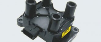
The coil is a pulse step-up transformer. It is she who ensures the conversion of low voltage, which is supplied to it from the battery or generator, into high voltage pulses.
Thanks to these impulses, a spark jumps between the electrodes of the spark plug, which ignites the working mixture in the cylinders. Like any transformer, the coil consists of two windings (primary and secondary), a magnetic circuit and a housing.
The module is structurally somewhat more complex and includes two coils and a switch, but its operating principle is identical to the coil.
Coil characteristics
Most likely, the electronics will signal a malfunction, but sometimes it is difficult to guess the causes of incomprehensible vibrations. Therefore, the first thing to do is to check whether the Priora’s ignition coil is working. It is worth noting that even some diagnosticians do not always quickly recognize a faulty part. Therefore, car enthusiasts have found several ways to check the ignition coil without visiting a service center.
What is the coil for? To ignite the air-fuel mixture in the cylinder, you need a high voltage current, but in a car battery it is low voltage. Thus, the ignition coil is something like a transformer, generating a current with high voltage. Its primary winding consists of only 150 turns, and in the secondary their number is much larger, which allows it to generate pulses using the spark plug as a spark gap.
Current passes through the primary winding and produces a magnetic field. When the starter opens the circuit, the energy stored in the coil is released and the cherished spark appears on the spark plug. The engine started.
To make the magnetic field as strong as possible, an iron core is located inside the coil. The main characteristic of a coil is the resistance value of its windings, which is taken into account when diagnosing ignition. Failure of such an important component threatens to completely stop the engine, not to mention interruptions in operation.
Principle of operation
The operation of the ignition coil is based on the principle of operation of a step-up transformer, when a small voltage of 12 V is converted into several thousand volts.
Voltage conversion occurs thanks to two windings - primary and secondary, which were mentioned above. In the first, a decreased U is created, in the second, an increased one.
Depending on the type of device, the location of the windings and their design differ.
Principle of operation:
- The breaker closes the electrical circuit and voltage is supplied to the primary winding. Due to this, a magnetic field is generated in the coil.
- After opening the circuit, the magnetic field disappears, but passing through the secondary winding it generates a high voltage in it.
The operating principle of the ignition coil is clearly presented in the video.
Coil types:
- Regular.
- Individual.
- Two-terminal.
Regular ignition coil
Here the primary winding is a metal core (to increase the magnetic field) around which 150 turns of thin insulated copper wire are wound, the ends of which are brought out to the housing.
The secondary high voltage winding is a thin insulated copper wire wound around a metal core with up to 50,000 turns.
The second winding is connected to the first by negative wires. The positive wire of the high voltage winding is brought out to the cover and connected to a special terminal.
Some models of ignition coils contain transformer oil as an insulator and for cooling purposes.
Custom ignition coil
Their design is more complex than conventional coils; they are installed on engines with electronic injection.
Structurally, they also have two windings, which differ from each other not only in the number of turns and wire thickness, but also in the reverse order of winding.
So in the primary winding the core is located as usual inside, and in the secondary winding outside. Also in the secondary winding, in order to cut off very high voltage, a diode is provided.
Also, thanks to special design solutions, it became possible to supply high U not to the distributor, as is the case with a conventional coil, but directly to the spark plugs.
Two-pin
Such an ignition coil immediately supplies voltage to the spark plugs of two cylinders, i.e. on a four-cylinder engine there will be two of them and they will be combined into one block, which is essentially a four-terminal coil.
Reel design and operation
The modern bobbin is a simplified version of the Ruhmkorff induction coil. It was named after the German-born inventor Heinrich Ruhmkorff, who was the first to patent a device in 1851 that converts low-voltage direct voltage into high-alternating voltage.
To understand the principle of operation, you need to know the structure of the ignition coil and the basics of radio electronics.
This is a traditional, common VAZ ignition coil, used for a long time and on many other cars. In fact, this is a pulse high-voltage transformer. On a core designed to enhance the magnetic field, a secondary winding is wound with a thin wire; it can contain up to thirty thousand turns of wire.
Causes of malfunctions
Ignition coils are reliable devices and the main reasons for their failure include: insulation breakdown, limiting service life.
Below we list other reasons why a device may fail.
| 1. Aging and mechanical damage. | During operation, the materials from which the ignition coil is made lose their strength, begin to crack and collapse, and various liquids (oil, antifreeze, etc.) can affect the device, which negatively affects its service life. There is only one solution - replacement. |
| 2. Damage or oxidation of the contact connection. | Penetration of moisture under the hood, a humid climate, after fording, improper washing of the engine or car, all this can affect the condition of the contacts and their rapid oxidation. |
| 3. Vibrations. | Individual ignition coils of electronic injection vehicles are very sensitive to vibrations. For example, if the motor is tripping, or one of its supports is out of order, it vibrates strongly. Also, very bad roads, which are not uncommon here, can cause severe shaking and affect the position of the reels. |
| 4. Overheating. | The same applies to individual coils, which are located near the cylinder head, where the temperature is highest. In the intended temperature conditions of the engine operation, nothing will happen, but if, as a result of poor quality coolant or for other reasons, the engine overheats, this will negatively affect the ignition coil as a whole. |
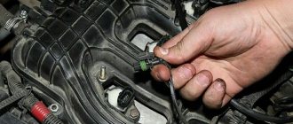
Removing and installing a coil on a Priora
To change the ignition system element in a 16 valve engine, follow these steps:
- Park the car level, securing it with the hand brake.
- Raise the hood and remove the negative from the battery.
- Undress the motor by removing its plastic protective casing.
- Find the spare part you need, and then the wire block connected to it.
- Squeeze the wire block clamp and turn off the power.
- Using the 10th key, unscrew the bolt that secures the part to the metal.
- Carefully remove the spool, trying to move it vertically. It would be a shame to damage the wiring at the very last moment.
- Remove the faulty part and replace it with a new one. Tighten the fastening bolt, connect the wire block and place the negative on the battery. Check functionality.
Signs of breakdown
The reel has a reliable design and its service life is significant. And yet this element can also fail.
The main signs that the ignition coil is not working properly are:
- Inability to start the power plant;
- The inscription “Check Engine” appears on the dashboard (on cars with an ECU), and when scanning the system, code P0363 is displayed, indicating a malfunction of the ignition module (on modern injection cars);
- Decrease in power unit performance;
- Misfires, which causes the engine to “trouble” (with time the problem becomes more pronounced);
- Dips when reaching certain crankshaft speeds.
It should be noted that these malfunctions are also typical for other elements of the ignition system, for example spark plugs, so before you “sin” the coil, you should check the entire circuit coming from it.
Symptoms of a bad coil
There are many symptoms of coil failure and sometimes it is very difficult to determine that the coil is to blame. If such symptoms appear in your car, then you should pay attention to the ICD.
Signs of coil failure:
- One of the cylinders does not work;
- The car does not develop power;
- Jerking when pressing the gas pedal sharply;
- The engine shakes at idle;
- Increased vibration at idle;
- Floating speed;
It should also be noted that if the ignition coil is faulty, misfires will appear in the cylinders, as a result of which the ECU will turn off the operation of the faulty cylinder and signal this by turning on the “Cheek Engine” lamp. When “Cheek Engine” appears on the car, it is necessary to diagnose the system. If there are misfires, the ECU will display errors 0301, 0302, 0303, 0304. Where the last digits of the codes are the cylinder number.
It is not recommended to operate a car with a faulty ignition coil; this can lead to failure of the catalyst.
Finding the origin of the problem
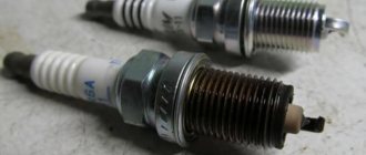
First you need to check the performance of the spark plugs, and this check may indirectly indicate a coil malfunction.
To check, you just need to unscrew the spark plugs, insert them into the tips of the high voltage wires, massage them and turn the crankshaft several times with the starter. In this case, you should look at the spark that forms between the electrodes.
If it is discovered that a spark plug is not working correctly and the spark in it is formed intermittently, it should be replaced and a known good one installed in its place.
If a working spark plug works intermittently, check the high voltage wire.
If the interruptions persist even when the wire is replaced, then in carburetor cars the distributor is inspected next, and only then the coil.
In injection cars equipped with a module, there is no such distributor, so you can immediately start checking the module.
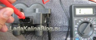
Checking these elements will not be particularly difficult, and the only equipment you will need is a multimeter with the ability to operate in ohmmeter mode, with a measurement range of up to 200 MOhm.
To make it more clear, let’s look at how these ignition elements are checked on different cars.
Manufacturers and prices of analogues - which ignition coils are better for the Priora
No one, not even AvtoVAZ, promises that the analogue will work as long as the standard model. There are a sufficient number of options on the market. It will take quite a long time to determine which is better. The following components are suitable for Priora 16cl:
- SOATE (manufactured in Stary Oskol) (article 2112-3705010-12), price – 1,200 rubles.
- MZATE-2 (article 59.3705), price - 1,000 rubles.
- Baker Priora 2112-3705010-10 – 1100 rubles.
- Fenox IC16085 (STK) – 1,300 rubles.
Basic Verification Approach
Since the windings play a key role in the operation of ignition coils, the first thing that needs to be checked, regardless of the type of device, is their resistance.
Thus, the resistance indicators of the primary winding can vary according to different data:
- from 0.6 to 4 Ohm;
- from 0.5 to 3.5 Ohm.
Secondary:
- from 6 to 15 kOhm;
- from 3 to 11 kOhm.
The indications are different because they can be different for each car model, so it is important to study the documentation for the car and the technical characteristics of the coil itself.
It is also important to understand that for each type of coil, indicators such as the inductance of the primary winding, the resistance of both windings, energy, duration and spark current may differ.
Measurements are performed with a multimeter or a regular ohmmeter.
If there is a strong deviation from the standard data, the ignition coil is most likely damaged. But there is no need to rush to change it; there are other ways to check.
Briefly about ignition
To understand why there is a reel in a car (this is a popular name), and what part it takes in ensuring movement, you need to at least generally understand the structure of ignition systems.
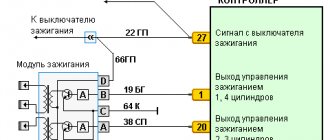
A simplified diagram of how the reel works is shown below.
The positive terminal of the coil is connected to the positive terminal of the battery, and the other terminal is connected to the voltage distributor. This connection scheme is classic and is widely used on VAZ family cars. To complete the picture, it is necessary to make a number of clarifications:
- The voltage distributor is a kind of dispatcher that supplies voltage to the cylinder in which the compression phase has occurred and the gasoline vapors should ignite.
- The operation of the ignition coil is controlled by a voltage switch; its design can be mechanical or electronic (contactless).
Mechanical devices were used in old cars: the VAZ 2106 and the like, but now they are almost completely replaced by electronic ones.
Checking the coil for VAZ 2101-2110
First, let's look at the sequence of checks on VAZ cars. Moreover, checking the carburetor for VAZ-2101 and VAZ-2110 is no different, the only difference is in the readings.
Next is the verification process itself:
- It is better to test the coil when it is removed from the car. Before starting removal, disconnect the negative terminal from the battery. From the coil we disconnect the wires from the side terminals, as well as the central wire. It is better to mark the wires from the side terminals so that they are not confused during installation.
- Loosen the coil fastening and remove it. Before checking with a multimeter, we clean it from dust and dirt, especially paying attention to the terminals. Then we inspect it for external damage. If there are any, further checking is pointless; it is better to replace it immediately;
- Checking the primary winding. To do this, switch the multimeter to ohmmeter mode and connect its probes to the side terminals. Different types of coils were used on different VAZ models, so you need to know which resistance readings are correct for them. So, for the B-117A model, used on classical models (VAZ-2101-2107), the resistance of the primary winding is 3.07-3.5 Ohms. And on classic models with a contactless system, coils marked 27.3705 are used; this parameter is 0.4-0.5 Ohm. On VAZ-2108-21099 cars, as well as VAZ-2110 carburetor, models with numbers are used - 3122.3705 and 8352.12. For the first of them, the resistance of the primary winding is considered normal in the range of 0.39-0.47 Ohms, and for the second - 0.37-047 Ohms;
- Next, the secondary winding is checked. To do this, switch the multimeter to the kOhm measurement mode, leave one of its probes on the side terminal, and connect the second to the central terminal. For a working B-117A coil, the resistance of the secondary winding should be 7.4-9.2 kOhm. For model 27.3705 this parameter should be around 5.0 kOhm, for 3122.3705 - 0.4 kOhm, and for 8352.12 - 1.0 kOhm;
- The last thing to check is the insulation resistance. To measure this parameter, switch the multimeter to measurement mode in MOhm. To measure, we connect one probe to the coil body, and connect the second to each terminal in turn. When measuring this parameter on all specified models, the multimeter should show at least 50 MOhm;
- If any of the parameters does not match the specified values, then the coil is faulty and must be replaced.
Checking the performance of the coil
| № | Examination | Description |
| 1 | Visual inspection | We remove the coils from the cylinders. |
| First, let's inspect the rubber part. There should be no breaks or cracks on it, and if there are any, it means that the coil has served its purpose and needs to be replaced. | ||
| Then we look inside, see what condition the internal spiral is in, its position. | ||
| 2 | Checking the primary winding of the coils with a multitester (checking Priora coils with a multitester) | Before connecting the device to the coil, its internal resistance must be checked to take into account possible errors. |
| We connect the tester to the primary winding. If the device shows no more than 0.5 Ohm, taking into account the measurement error, then everything is fine with this coil. | ||
| 3 | Checking the secondary winding of coils with a multitester | Switch the tester to 2000 kOhm |
| We connect the probes to different parts of the coil, observing polarity: the red contact is to the spring under the rubber cap, and the black one is connected to the middle contact of the connector. A working Priora ignition coil shows a secondary winding resistance of 342 kOhm. A faulty tester will show infinity. |
You need to remove the coil from its place by disconnecting the negative terminal of the Priora battery. Decorative plastic is removed from the motor. Then you need to press out the plastic clamp and disconnect the coil from the wiring, after which the fastening bolt is unscrewed with a 10mm wrench and the device is removed from the spark plug well.
Currently, there is simply no trust in standard Priora coils. Some immediately replace them with foreign-made devices, with Bosch products being especially popular. Since the designers have not eradicated this hereditary problem in the Priora model, the owners themselves will have to correct it, investing not so small sums, because Bosch sometimes asks for no less than 1,500 rubles apiece.
Problems with coils can lead to sudden jerks in engine operation, speed surges, and cylinder failures. Therefore, if you have such symptoms, it is better to use the above information and replace the suspicious part before it completely fails. It also happens that the coil has not yet broken, but is already malfunctioning. This does not necessarily mean that a replacement is needed; some repairs will do, or rather cleaning of water condensation and dirt.
Experienced drivers have verified that after a couple of hours of painstakingly cleaning the coils, the motor stops tripping and works like new. It turns out that it did not burn out, but simply passed current in places. Such a nuisance can be eliminated even on the road. It is enough to remove condensation and wipe important parts with gasoline to remove dirt. If you attach heat shrink to the coil, there will never be problems with interruptions again, and Priora will not spoil the mood of its owner.
Sometimes coils fail when the spark plug gap is incorrect. Checking the performance of the coil on a Priora car can be easily done by turning the crankshaft. To do this, you need to relieve the pressure in the fuel system and remove the fuel pump fuse. Then we remove the coil, insert a spark plug into its rubber tip, and connect the wires to the coil itself.
After this, we carefully place the experimental spark plug on the cylinder block, ensuring contact between the spark plug and the mass. Do not touch the spark plug coil with your hands to avoid getting an electric shock. Now you need to turn the crankshaft. An assistant does this while you look carefully at the candle. A spark should appear between its electrodes when the starter is turned on and the shaft is turned. This is an indicator of her work.
You can check the coil power circuit. You need to take the multitester mentioned above and connect its probes to its terminals. If you turn on the ignition at this moment, the tester should show a voltage equal to that at the battery terminals. Otherwise, it is necessary to check the circuits for opens and shorts. If the power and control circuits are working properly, but when checking there is no spark on the working spark plug inserted into the tip, then the coil is faulty and will have to be replaced.
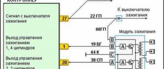
Testing the ignition module on a VAZ-2110 injector
On injection cars, for example, VAZ-2110, the module check is performed slightly differently.
The check sequence is as follows:
- We inspect the module for damage. Even small cracks can cause a module to fail, if not now, then in the near future. Therefore, such a module does not need to be checked, but replaced immediately.
- Disconnect the block of wires going to the module. First, check the voltage supply to the module. To do this, switch the multimeter to voltmeter mode, connect one of its probes to terminal “A” (the letters are stamped on the block), and the second to “ground” and turn on the ignition. If the wiring is good, the voltmeter should show 12 V or close to it.
- Then we take a 12 V test light and connect it to terminals “A” and “B” on the block. Then we turn on the starter and look at the “control”; it should blink when the starter is running.
- We switch the multimeter to ohmmeter mode with the measurement parameter in kOhm and measure the resistance of the secondary winding of the coil at the paired terminals. To do this, we connect one probe to the terminal that supplies an impulse to cylinder 1, and the second to the terminal of cylinder 4. A working module should have a resistance of about 5,4
kOhm - We take another measurement, but now on terminals 2 and 3 of cylinders. The readings at these terminals should be normal. A strong discrepancy in resistance at paired terminals indicates a module malfunction and the need for repair or replacement.
Performance check: how to check ignition coils on a Priora
Before you start replacing the ignition coils, you definitely need to check them and inspect them. Cracks, chips, and other damage to its body are unacceptable. If you see that the plastic is damaged, it means the part has overheated and cannot be used further.
The answer to the question of how to check an element of the 16-valve Priora ignition system is not limited to inspection. First you need to swap them and see if there are interruptions in the other cylinder. If there are interruptions, the problem is in the coil. There are several ways to use devices. To work you need:
- Secure the car in place and turn off the engine.
- Remove the negative from the battery.
- Disconnect the part from the motor, and then connect a fully functional spark plug to it.
- Turn off the fuel pump.
- Use protective equipment against electric shock, this is a must!
- Turn on the ignition and crank the starter. The spark plug should spark during normal operation.
- Sometimes repair of the Priora ignition coil begins after receiving data from the ECU. The codes start with 0301 and end with 0304, indicating each cylinder accordingly. However, the problem is displayed in the coil-plug module, so the culprit will have to be found out separately.
Now we check the ignition system element on the Priora with a multimeter. For this and further work with components, models AZ-1 or MD-1 are suitable. For this:
- Remove the part to be examined from under the hood.
- Set the measurement switch to the “200 Ohm” position, connect the probes. The display should show “0” or values close to it.
- Using probes, the external winding is checked. Pinout – 1.3. The display should show exactly 0.08 Ohm. The error is the number that the display showed during calibration; it must be subtracted. If nothing is shown, check that the probes are accurately touching the winding. If there is contact, but there is no result, the winding is broken and needs to be replaced.
- Set the multimeter to 2 MΩ measurement limit to test the high voltage winding. Connect the black probe to the terminal of the second connector, and the red probe to the terminal of the coil. The indicator should be 342 kOhm - but only for a cold part. It should be cooled before testing. This also requires checking the exact contact with the probe.
Remember that the winding of this spare part does not change, but the tip can be easily changed. Most often, repairs are limited to routine replacement - in order to be completely sure of the tightness of the part.
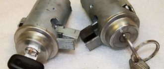
Egnition lock
Removing the “seven” lock
The ignition system on the domestic seven includes two main components - a coil and a module. The lock, in turn, consists of several parts - the switching mechanism itself, as well as the contact circuit. Each of these components is independent in its design, so if one of them breaks, it can be replaced without completely changing the lock. As for repairs, the VAZ 2107 ignition module can be repaired at home if you have all the necessary tools and an idea of how this procedure is performed.
On a carburetor or injector, the functionality of the lock can be determined using a special tester - a multimeter. To check contact ignition, the multimeter probes should be connected to the outputs on the lock one by one, and the output should correspond to one or another position of the key. If the contact group is operational, the multimeter will display a resistance that tends to zero. If the resulting indicator is different, this indicates the need to repair the contact group or replace it. In some cases, such parameters may be due to oxidation or burnt contacts, which can be corrected without replacing the group.
Video on repairing KZ VAZ
Often, when the ignition module breaks down, the car owner immediately runs to the store and buys a new one. But, for the VAZ-2112 there is an alternative method - repair. Of course, without proper knowledge in auto electrics, it will be difficult to understand all the circuits and communications. This article will tell you in the most accessible way how to repair the ignition module with your own hands.
Display Guide
So, we figured out where the VAZ module and ignition coil are located and what functions they perform, now let’s talk about setting them up. If the system torque is set incorrectly, this will cause increased gasoline consumption, as well as detonation of the power unit (the “fingers” will start knocking). In general, the operation of the motor will be unstable.
To set up the ignition of a VAZ 2107, you need to perform several steps, all of them are described in detail below:
- First, you need to correctly adjust the gap that exists between the interrupter device. To do this, you should dismantle its cover in advance and clean the contact surface. At the same stage, it is necessary to check the connection of the contacts - the elements must come into contact over the entire surface, and not just in certain areas. If the contacts are poorly connected, you should try to bend them slightly. You can also try sharpening the plane a little.
- Having done this, we move on to an important stage. You need to turn the crankshaft until the contacts open as much as possible. Using a feeler gauge, you need to increase the gap to approximately 0.45 mm. It should be noted that during this, the probe between the contacts should move with low resistance.
- The crankshaft rotates until the “ignition timing” mark marked on the pulley itself. Having done this, a voltmeter should be connected to the terminal of the interrupting mechanism; if it is not there, a regular test light can be used. We are talking directly about the breaker terminal, which is connected to the coil. Using a 13mm wrench, you need to slightly loosen the nut securing the breaker to the BC.
- After these steps, you need to turn the key in the lock, but do not start the engine; at the same time, the breaker body must be turned counterclockwise. When you notice that the light has gone out, you need to start turning the housing in a different direction until the light comes on again. If the control light is on, this indicates that the moment of spark transmission through the high-voltage wires has been set. Once the torque has been established, the breaker fixing nut should be tightened until it stops.
As for checking, this is easy to do. When the car is traveling at a speed of 40 km/h, you need to press the gas so that the vehicle quickly gains power. During rapid acceleration, a brief detonation should occur until the car can accelerate to 60 km/h. If this is so, then the moment was set correctly and for some time you can forget about this procedure.
Sorry, there are no surveys available at this time.
REPLACING THE DEVICE
If the indicators do not correspond to the above values, the ignition coil is considered faulty. Such a device must be replaced with a working one, which can be purchased at almost any spare parts store. When purchasing the device, you must inspect it and check the availability of documents: technical passport and certificate.
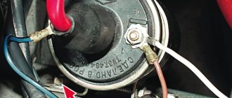
Removing the ignition coil on a VAZ2107 car is carried out with the battery disconnected. Use a wrench to unscrew the nuts on the contact and mounting studs. The faulty device is removed. A spare part is installed in its place and secured and connected. Now you can connect the battery and start the engine.
Sources
- 7vaz.ru/remont/diagnostika-i-zamena-katushki-zazhiganiya.html
- autocentrum.ru/brands/lada/17209-obzor-sistemy-zazhiganiya-vaz-2107-katushki-i-drugih-elementov-posobie-po-vystavleniyu.html
- drive2.ru/l/487397562748240344/
- 21074.ru/elektrooborudovanie/kak-proverit-modul-zazhiganija-vaz-2107-inzhektor-multimetrom/
- bumper.guru/klassicheskie-modeli-vaz/elektrooborudovanie/zazhiganie/zazhiganie-2107/katushka-zazhiganiya-vaz-2107.html
Individual ignition circuits and connection points for system diagnostics.
Below are individual ignition diagrams. The diagrams show the connection points of an oscilloscope probe and high-voltage sensors to the coil being diagnosed, for diagnosing the system using voltage oscillograms in the primary and secondary circuits of the coil
Diagram of an individual ignition system with an external power stage for controlling the primary winding of the coil (the diagram is shown for one cylinder).
- Connection point for the black alligator clip of the oscilloscope probe.
- Scope probe connection point.
- Signal pickup point in the secondary circuit using a universal clamp-on capacitive sensor “Cx Universal”.
- Installation location of the universal surface-mounted inductive sensor “Lx Universal” for picking up a signal in the secondary circuit.
- Accumulator battery.
- Ignition switch.
- Individual compact ignition coil without a built-in power stage for controlling the primary winding of the coil.
- Spark plug.
- Engine control unit (or switch).
A power stage for controlling the primary winding of the coil (switch) can be built into the body of an individual ignition coil.
Diagram of an individual ignition system with a power stage for controlling the primary winding built into the coil (the diagram is shown for one cylinder).
- Connection point for the black alligator clip of the oscilloscope probe.
- Scope probe connection point.
- Installation location of the universal surface-mounted inductive sensor “Lx Universal” for picking up a signal in the secondary circuit.
- Accumulator battery.
- Ignition switch.
- Individual compact or rod ignition coil with a built-in power stage for controlling the primary winding of the coil.
- Spark plug.
- The engine control unit.
Diagnostics based on the primary voltage of individual ignition coils
To diagnose an individual ignition coil based on the primary voltage, it is necessary to view the voltage oscillogram at the control terminal of the primary winding of the coil using an oscilloscope probe.
Oscilloscope probe.
To record a voltage oscillogram at the control terminal of the primary winding, an oscilloscope probe must be connected to analog input No. 5 of USB Autoscope II, a black alligator clip must be connected to ground on the engine, and the probe probe must be connected parallel to the control terminal of the primary winding of the ignition coil.
Connecting an oscilloscope probe to the control terminal of the primary winding of an individual ignition coil.
Next, you need to start the engine being diagnosed. In the “USB Oscilloscope” program window, you must select “Manage => Load user settings => => Ignition => Ignition_Primary”. Now, the program window will display an oscillogram of the voltage on the primary winding of the diagnosed ignition coil.
Voltage oscillogram at the control terminal of the primary winding working individual ignition coil.
- The moment of opening of the power transistor of the switch (beginning of energy accumulation in the magnetic field of the ignition coil).
- The moment of closing the power transistor of the switch (the current in the primary circuit is abruptly interrupted and a breakdown of the spark gap occurs between the electrodes of the spark plug).
- The spark burning area between the spark plug electrodes.
- Damped oscillations that occur immediately after the end of the spark burning between the electrodes of the spark plug.
Voltage oscillogram at the control terminal of the primary winding faulty individual ignition coil. A sign of a malfunction is the absence of damped oscillations after the end of the spark burning between the spark plug electrodes (section o).
Some types of individual ignition coils have a built-in power stage that controls the primary winding of the coil. The control terminal of the primary winding of such ignition coils is located inside the coil body and is inaccessible for connecting an oscilloscope probe to it. This makes it impossible to diagnose such an individual ignition coil based on the primary voltage. In this case, the ignition coil is diagnosed using the secondary voltage using a universal clamp-on capacitive sensor “Cx Universal” or a universal clamp-on inductive sensor “Lx Universal”.
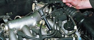
Connecting and replacing VAZ short circuit
The procedure for removing and installing the ignition coil on old VAZ models:
- First, disconnect the central high-voltage wire leading to the distributor (ignition distributor).
- Disconnect all power wires from the coil contacts. Since they are fastened with nuts, you will need an 8 wrench for this.
- If you don’t know which wires to connect to which connector later, it’s better to immediately remember or mark them somehow, so that later during installation you can connect them correctly.
- Unscrew the coil housing. It is attached to a clamp (clamp), which is pressed to the car body with two nuts.
- After the work has been done, you can remove the ignition coil and replace it if necessary.
For new type VAZ cars:
- We remove the “minus terminal” from the battery.
- Remove the top protective cover of the engine. If the engine volume is 1.5 liters, then this part is missing and this step is skipped.
- We remove the high-voltage wires from the coil.
- Now, using a 13mm wrench, unscrew the two fasteners.
- Using a 17mm wrench, loosen one bolt securing the coil.
- We take out the module.
- Use a hexagon to unscrew the coil from the holder.
- Assembly is carried out in reverse order.
Particular attention should be paid to the connection, since high-voltage wires must be located in the strict order provided for by the design. If this is not done, the car will stall or the engine may not start at all.
Replacing the ignition coil on a VAZ is quite simple. Even a novice motorist can do this in his garage, and if everything seems too complicated, contact a car service center. Particular attention should be paid to the choice of product, since this will determine how well the engine and ignition system will work.
Double coil
There are two more types of coils - two-terminal and individual. Two-terminal coils are used in an electronic ignition system with a direct spark supply to the spark plug.
Two-lead coil. Very often used on motorcycles with an electronic ignition system. A special feature is the presence of two high-voltage terminals. They can simultaneously receive a spark from two cylinders.
Its internal design is practically no different from the general type coil. But such a coil has two outputs for supplying an impulse. That is, when the coil is operating, a pulse is sent to two spark plugs at once. Since when the power plant is operating at the same time, the end of the compression stroke in two cylinders cannot be, but only in one cylinder, then in the second the spark discharge that jumps between the electrodes of the spark plug will not have any useful function - an idle spark. But with further operation of the engine, the situation will change - in the second cylinder there will be the end of the compression stroke and a spark is needed, and in the first cylinder it will be idle.
The two-terminal coil can have different ways of connecting to the glow plugs. One way is to send pulses through two high-voltage wires. The second is the use of one tip and one high-voltage wire.
Such a coil allows you to do without a distributor, but it can only supply a spark to two cylinders. And usually a car uses 4 cylinders. For such cars, a four-terminal coil is used, which itself consists of two two-terminal coils combined into one block.
Ignition system without runner
Installation of a four-terminal ignition coil (ignition module) from fuel-injected cars to carburetor cars.
A simple device for those who are tired of changing distributor caps and sliders. The efficiency of using these coils in the ignition system is much higher than classic ones, due to the reduction of losses when transmitting high voltage to the spark plugs. In a pair of slider and distributor cap, 30% of the spark energy is lost; there is no such deficiency in this system. Feel the effect immediately, in the form of improved engine performance, especially noticeable at idle speed. This circuit is a small add-on to the standard switch from a contactless ignition system, which can be soldered and started in a couple of hours.
L497 is an ignition controller located in a standard switch, the lower hall is standard, I took the upper hall with a built-in magnet, screwed it to the distributor cover approximately in the middle between the terminals and soldered a wire onto the slider, it turned out to be a phase sensor, who is too lazy to do this, they can screw a standard one from the injector .
A signal inverter from the sensor is made on the KT6116; it can be replaced with any low-power PNP structure. IRFZ44 transistors are parallel switches; they can be replaced with any other field switches with an insulated gate and low channel resistance, so as not to be hung on a radiator. The BU941 is a powerful composite transistor with built-in voltage protection, operating on the ignition coil, which can be replaced with the domestic KT898 (be sure to ensure good heat dissipation). The CD4047 chip is included in this circuit as a reset trigger; it can be replaced with our 561 series, for example K561TM2 in the corresponding connection.
The circuit works like this: the signal from the standard hall sensor comes to the fifth leg of the L497 chip, is processed there and from the fourteenth leg goes to the IRFZ44 parallel switches, one of them is opened by the CD4047b chip and then to the base of the switching transistor. Leg 3 of the CD4047 chip receives a signal from the same sensor and switches the transistors with each spark. The second hall is needed so that when starting the engine, the spark hits the desired cylinder, the signal from it resets the trigger to its original state, and then only confirms the choice of cylinders (it will run without it, it will only start every other time).
I placed the device in a standard switch with hinged mounting, and screwed the key transistors to the radiator. For those who will use two two-terminal coils instead of one four-terminal one, take exactly the same ones. This modernization of the ignition system cost me the cost of the coil and high-voltage wires to it, the remaining parts cost about 150 rubles.
Author: S.V. Tikhomirov (Pukhov). E-Mail: zasosu2009 [dog] ya.ru