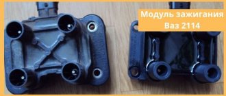
The VAZ 2114 ignition module is the heart of the engine system as a whole, the cycles of which allow the spark plug to produce a spark and start the fourteenth. The device is needed for the process of generating high voltage current transmitted to the spark plugs through high-voltage wires (4 wires coming from the module). In common parlance, this app. The part is also called the ignition system coil (named after the fundamental two parts of the device itself).
Ignition coil VAZ 2114
Replacing ignition module 2114
It all started 2-3 months ago. I went on some errands, started it, warmed it up, sat down and drove off. I drive about 300 meters and the check light flashes... the engine seems to be running on 3 cylinders... basically I stopped and turned it off (what the hell did I say to myself)... With the emergency lights I barely made it home, parked the car and went to the store. I bought new NGK spark plugs and BB wires, installed them and started them, but it was like the car was spinning. Okay, I went for diagnostics while I was driving and the check went out and everything was fine. I did the diagnostics - they said there were no problems... Hmmm... Okay, I'm driving for another week... I went to a car service center (Near the house)... I arrived and I say such things... I measured the compression, in all pots there are 12, measured the pressure in the fuel rail - everything is fine, I adjusted the valves at the same time... The car started up and still rattled... I went home upset.
I gave up on the car - it drives and drives while it drives, “I said to myself,” and drove for another week... On the weekend, having collected my thoughts and spirit, I decided to go to the service center again. This time they cleaned the throttle, injectors, replaced the IAC sensor, and What do you think, what do you call sausage...
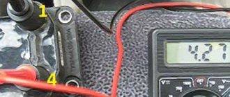
While sitting at work, I thought maybe it was connected to the ignition module... and it started dripping in different directions... I came across an article where they check the ignition module using a multimeter. I read in the article that the resistance between contacts 1 and 4, 2 and 3 should not exceed 5.8 kOhm
, Having found a multimeter at home.
Multimeter
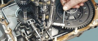
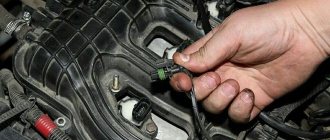
I went to the car, removed the ignition module by unscrewing 3 bolts and began to measure the resistance... and then it turned out that the module was long overdue for replacement...
Resistance between 1 and 4
Resistance between 2 and 3
Horrified, having installed the module, the store went back. Upon arrival at the store, they offered me a choice of 2 reels, one of them made in Russia and the other made by Bosch Germany, the difference in price was a little more than 1000 rubles... At that time there were problems with finances, so I had to buy something cheaper.
Having put the new module in place, the car simply whispered (I made 3 laps around the area with pleasure).
Checking the ignition module of a VAZ-2114 car with a multimeter
Internal combustion engines require fuel and an igniter to operate. The ignition module plays this role on fuel-injected cars.
The article will describe checking the VAZ-2114 ignition module with a multimeter.
The purpose of the ignition module (IM), operating principle, and main malfunctions will also be described in detail.
Purpose and principle of operation
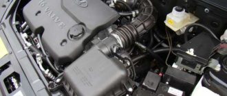
The ignition module of a VAZ-2114 car with an injection 8-valve power unit is located directly opposite the engine block on the spark plug side. This arrangement is most effective for supplying high-voltage wires to the spark plugs. The device is mounted on the wall of the engine compartment. This position was not chosen by chance. This way the MH interacts less with vibrating parts of the car.
The device that comes with the described car model is of the block type. One housing contains 2 inductors and 2 discharge voltage regulators. The device operates according to the following principle:
- A pulse signal passes from the crankshaft position controller to the on-board computer.
- The signal is confirmed by a pulse signal from the Hall sensor of the ignition system.
- Both signals are calculated in the on-board computer and transmitted as current to the module.
- The module converts 12 volt voltage into high current.
- From the coil, the voltage is supplied to the spark gap, which forms a pulse voltage.
- The voltage passes through the high voltage wire of cylinders 1 and 4 to the spark plug.
- The spark plug is discharged by a spark, igniting the fuel in the cylinder.
- During the discharge, spark plugs 2–3 also receive voltage, but its power is adjusted by the spark gap.
All components are made of high-strength plastic with an aluminum plate for mounting to the engine. Additionally, both coils are filled with insulating solution. On the body of the device there are only 4 contact sockets for high-voltage wires and an electrical power socket.
Subject to all operating rules, the ignition module is a very reliable electronic device, but it is quite fragile. If the electrical circuit has a number of damages and is often subject to short circuits, then the coils or arresters fail.
Any malfunction of the MH leads to interruptions in engine operation. The following will describe the main symptoms of a malfunction of this device.
Repair
If you do not want to completely change the module, you can try to bring it back to life by repairing it. The task is not too difficult, so doing it yourself is more than possible.
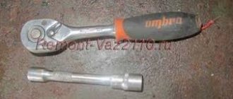
- Arm yourself with 17, 13 and 10 mm socket wrenches, a screwdriver, a soldering iron, aluminum flux, nail polish, stranded wires and a 5mm hex wrench.
- The weakest point of the ignition module is the contacts.
- Start the car, pull the contacts. This will help determine if the problem really lies with poor connections.
- Stop the engine and remove the module. We told you how this is done in the previous section.
- Open the module by simply prying up the housing with a flat-head screwdriver.
- Inside there is a board with silicone film. Clean it up.
- Remove aluminum from explosive contacts.
- Now comes the most difficult stage - working with a soldering iron. The task is to solder the new wires to the place where you just removed the old ones.
- Clean the surfaces from deposits, place the board on the stove and heat it to approximately 200 degrees. You can determine the desired heating level by a slight smell.
- Start soldering. The ends of the wires are connected to the module.
- Treat the resulting new contacts with regular colorless nail polish.
- Reassemble the module in reverse order, turn on the ignition.
- If everything works well, arm yourself with sealant and glue everything as firmly as possible.
- If a transistor or switch fails, it will be impossible to repair it. These elements can only be fully replaced. But don’t worry, because their price is approximately 200-300 rubles. That is, purchasing new elements will cost a total of 500 rubles maximum.
Malfunctions
During the operation of the car, problems arise in the operation of the engine. They are often associated with interruptions in the ignition system. The main symptoms are as follows:
- The appearance of code P0351 indicates the absence of a spark on the spark plugs of the first stroke.
- Error P0352 indicates a lack of spark on the second stroke candles.
- Codes P3000, 3001, 3002, 3003, 3004 indicate a missed discharge to the spark plugs.
In these cases, the power unit operates with a loss of power, and stability at idle speed is lost. The engine stalls during a sharp start, or when engaging any of the gears. Heating also increases and fuel consumption increases significantly. If there is no ignition, the smell of unburned gasoline appears. It becomes almost impossible to start such an engine. Such symptoms require immediate intervention and checking the VAZ-2114 ignition coil.
Examination
Often problems with MH begin after replacing high-voltage power wires. Many people may simply make a mistake by mixing up the connection points to the candles. The pin numbering scheme is presented below.
Also, owners of the injection-type VAZ-2114 often replace the standard wires with modern silicone analogues. This is absolutely impossible to do. Silicone high-voltage wires have significantly higher resistance. When replacing, it is also important to consider the length of each wire. Standard wiring has the following parameters:
- The wire of cylinder 1 has a length of 56 cm and an operating resistance of 2.5 to 3.8 Ohms.
- A 44 cm long wire with an operating resistance of 2 to 3 Ohms goes to the second cylinder.
- 3 wire 36 cm long, resistance from 1.6 to 2.6 Ohms.
- 4 wire 32 cm long, resistance from 1.4 to 2.1 Ohm.
This is worth considering, since high resistance significantly reduces the spark discharge current.
Also, a problem with the ignition module may arise due to problems with the fuse responsible for its protection. The fuse is located behind the cover under the dash on the front passenger's side. This is the very first fuse located between relays 1 and 2. The element should be checked for the presence of a working jumper inside the housing. The test can be carried out visually, or using a tester in dial mode. Be sure to replace the burnt-out protective element with a complete analogue, rated 15 amperes. It is also worth checking the incoming voltage. This requires:
- Set the tester to DC voltage measurement mode up to 20 volts.
- Connect the red test probe to the fuse terminal.
- Connect the black probe to ground.
- Turn on the ignition.
The voltmeter should give a reading equal to the battery charge. If there is voltage, it means it is reaching the ignition module.
Module
Many owners of the car described do not know how to check the VAZ-2114 ignition module using a multimeter. First you need to test the device with the engine running. This requires:
- Start the power unit.
- Ask an assistant to keep the speed within idle.
- Wear a glove or take a dry cloth.
- Remove the power wires from the module sockets one by one.
Each removed wire must be brought to the power unit block. Without touching, a spark should discharge from the tip. A blue spark and a discharge accompanied by a crackling sound will indicate the necessary supply of discharge current. In this case, the engine should respond to the removed working wire by reducing the speed. If a wire is detected from which the spark does not come or it is quite weak, the engine speed will not change.
The previously described error codes from the on-board computer can also help in finding the wire with no spark.
For more effective testing, it is necessary to dismantle the ignition distribution device and carry out a test with a tester. This is easy to do if you follow these instructions.
First you need to dismantle the device. This is done as follows:
- Disconnect the ground terminal from the battery.
- Remove 4 high-voltage wires from the MZ sockets.
- Disconnect the electrical power plug.
- Unscrew the 3 nuts securing the module.
- Remove the device.
Next, a mandatory visual inspection of the device is carried out. The ignition module is a rather fragile device. The presence of defects on the housing, cracks and dents, can cause an internal short circuit. You also need to pay attention to the sockets for power cables. There should be no oxidation or dirt on the terminals. Any malfunctions should be eliminated by cleaning with a solvent. Next you need to check the connecting plug. Its contacts also need to be cleaned. Below is a step-by-step guide on how to check the VAZ-2114 ignition module with a multimeter.
Checking the connecting plug
First you need to check the incoming voltage to the module. This is done as follows:
- The multimeter is switched to voltmeter mode to measure DC voltage.
- The red measuring probe is connected to the incoming half of the module plug, with the central contact. It is he who is responsible for powering the device.
- The black test probe is connected to ground.
- Turn on the ignition.
The tester should show a voltage of 11.5–14 volts, equal to the battery charge.
Next, the incoming signal is checked. The voltmeter remains in the same position.
- The red probe of the tester is connected to contact “1” of the coming side of the plug. This contact is responsible for the distribution of pulse current for the cycle of candles 1–4.
- The black probe connects to ground.
- It is necessary to crank the starter a few turns.
The voltmeter should show pulse voltage. Contact “3” on the plug is checked in the same way.
Module plug
For this test, you need to switch the multimeter to resistance measurement mode. Next you need:
- Connect the red control probe to terminal “1”.
- Connect the black control probe to terminal “3”.
- The operating resistance should be within 0.5 Ohm.
In this way, both secondary windings of the ignition coils are checked. Any deviations in resistance will indicate an internal violation of the integrity of the winding.
Using the following test, the presence or absence of a short circuit is checked.
- The multimeter remains in resistance measurement mode.
- Connect the red test probe to the central contact of the plug.
- Connect the black test probe to the device body.
- The tester should not show any results. This will indicate that there is no internal short circuit. Any minimal resistance during this test is reason to replace the module.
The following check is needed to test the primary windings. The check is carried out as follows:
- The multimeter is switched to resistance measurement mode.
- Insert the red measuring probe into the “1” socket for high-voltage wires.
- Insert the black measuring probe into socket “4”.
- The operating resistance of the primary phase windings is 0.5 Ohm. Any data that differs from the nominal value can be recognized as the presence of an interturn short circuit in the primary winding of cylinders 1–4.
The test of sockets “2” and “3” is carried out in a similar way. Their operating resistance should also be 0.5 Ohm.
Additionally, you can check in the same way, but between sockets “1” and “2”. There are no internal connections between them. If there is resistance, the part is considered unsuitable for further use.
Main signs of failure
Drivers need to take into account during operation that breakdowns can occur both due to failure of the mechanical part and due to problems with the electrical system. Popular mechanical problems manifest themselves in the following factors:
- the lock is stuck in one position and there is no way to unlock it without using significant effort;
- the steering column is jammed;
- an attempt was made to gain unauthorized access to the lock using a master key or other object unsuitable for this purpose.
The electrical part may also fail. This can be determined by the following factors:
- the starter does not rotate after turning the key to the desired position;
- The dashboard indicator lights do not light up or go out after a short time;
- the operation of devices activated through the lock positions is unstable or absent.
Other factors that are less common among motorists may also occur. They are resolved according to the identified breakdowns.
You should not delay solving the problem that has arisen, as this can provoke unpredictable negative consequences.
Other reasons
If, after checking the ignition module of an injection-type VAZ-2114 car, no malfunction was identified, then you should pay attention to breakdowns or improper operation of adjacent devices.
- Powertrain control unit. It happens that after an electrical short circuit, the ECU loses its internal settings. To restore functionality, you need to disconnect the “+” terminal from the battery and connect it again. The ECU will enter a temporary reboot, and the module's operation may be restored. It is also worth carrying out professional diagnostics of the on-board network.
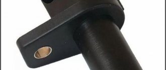
- Crankshaft position sensor. An important source of pulse signals. Its data affects the distribution of voltage from the ECU to secondary devices. It is necessary to check the functionality of this element, its wiring, and the protective fuse. If necessary, replace faulty parts.
- Hall Sensor. This device is responsible for the distribution of pulses. Signals are generated due to contact connection during rotation of the device rod. Any deviations in the supply of signals affect the operation of the ignition module.
- Generator. The high charge current of this mechanism often leads to complete burnout of the secondary winding of the MC. The first problem may be a faulty fuse. If such a problem is detected, it is worth checking the amount of voltage coming from the generator.
The system, which includes a Hall sensor, DPKV and ignition module, works by calculating the position of the crankshaft. This is how the exact order of the spark cycle on the cylinders is achieved.
Important! Very often, the performance of the MH is affected by careless operation of this device. The cause of failure may be:
- Lack of contact with the “mass”. This occurs when the 3 bolts securing the device are insufficiently tensioned. Periodic loss of contact leads to a break in the circuit. The newly appeared contact causes the discharge of a current of greater strength. This leads to internal burnout of the secondary winding of the coils.
- Lack of contact on spark plug caps. A poor connection leads to contact vibration, often high-voltage wires fly out and short to ground. This leads to damage to the MZ discharge contactor.
- Poor contact or oxidation at the battery terminals. It also leads to a short-term but powerful discharge of the primary winding.
- Spark plug gap. The manufacturer sets a fixed spark plug gap. The maximum value for spark plugs installed on injection engines can be 1.3 mm. A large gap leads to a spark hitting the housing. The spark is simply deflected to the side. A small gap size can lead to breakdown of high-voltage wires or the ignition coil itself. The high voltage pulse current is simply discharged back into the circuit.
Many car enthusiasts try to disassemble and repair ignition modules themselves. With proper knowledge of electronics, only the discharge regulator can be repaired. The coils will have to be rewound. But the main difficulty lies in the subsequent sealing and insulation of the inductors. Any remaining cracks will cause breakdown and failure. It is better to purchase and replace the MZ with an exact analogue.
For what malfunctions is it possible to repair the device?
Due to the fact that the ignition module by design includes a connection of two coils, it is difficult to repair. If there is a break or breakdown, as well as melting of the turns, the problem can be solved by replacing the device. This applies to any damage that appears inside the coils. The only option to correct the situation without replacing the device is to repair the damage to the solder joint.
Ignition module repair process
The repair procedure is carried out after preparing all tools and materials:
- a set of socket wrenches, you will need a tool for 10, 13 and 17;
- hexagon 5;
- flat head screwdriver;
- soldering iron with aluminum and flux;
- nail polish;
- multi-core conductors.
Restoring the ignition module operation is done as follows:
- The key is installed in the switch. The engine starts. Then you need to move the contact elements on the module to make sure they are not working.
- The power unit stops. The module is being removed.
- The device body is cleaned from dust. To disassemble, you need to open the case; this is done by prying it off with a screwdriver. Inside the device there is a board on which there is a silicone film; you need to get rid of it.
- Aluminum is removed from high-voltage contact elements. Old wires are removed.
- The next step will be soldering new conductors to the circuit. To do this, the surface of the collector device is cleaned from traces of plaque. Then the board must be installed on an electric stove and heated to approximately 200 degrees. As the temperature increases, a slight burning smell may be heard. This is not a problem for the circuit; heating it will simplify the soldering procedure.
- Then soldering is done. Using a soldering iron, flux and aluminum, the ends of the conductors must be connected to the ignition module. All contact elements of the conductors that are connected to the circuit must be treated with nail polish.
- Then the device is assembled in the reverse order and installed in the seat. After installation, the power unit starts up. If the repair solves the problem, then using a sealant, the device is fixed in place.
- If a transistor or switching device fails, then these components cannot be repaired, but they can be replaced. To do this, the parts are removed from the board and replaced with new ones.
Ilya Balashov presented a video with the result of soldering the ignition module using the example of a VAZ 2110 car.
Ignition coil VAZ 2114 8 valves, VAZ 2113, VAZ 2115
Here we consider the ignition coil of VAZ 2114 8 valves, VAZ 2113, VAZ 2115 model 2111-3705010-02 (54.37005) with injection engine 11183 (l,6i). The ignition coil of the VAZ 2114 injection 8 valve engine is described. The diagram of the ignition coil of VAZ 2114, 2113, 2115 is shown. The electrical diagram of connecting the ignition coil of VAZ 2114 injector 8 is presented. Malfunctions of the ignition coil of VAZ 2114 8 valves are given. The pinout of the ignition coil for VAZ 2114 injector 8, VAZ 2113, VAZ 2115 is shown.
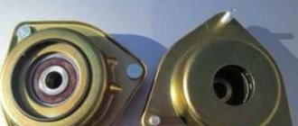
Description and purpose
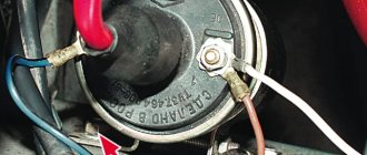
Ignition coil VAZ 2114 8 valves, VAZ 2113, VAZ 2115 are two two-output ignition reels mounted in a single casing. It is designed to convert low on-board voltage (12 volts) into high sparking voltage. Sparking occurs in two pots at once (1-4 and 2-3). The ignition solenoid is connected to the spark plugs by high-voltage wires with permanent tips.
| 1 — ignition coil VAZ 2114 |
| 2 - package of high-voltage wires |
Below, in the figure, the design of the ignition coil of the VAZ 2114 8 valves is presented
Connecting and replacing VAZ short circuit
The procedure for removing and installing the ignition coil on old VAZ models:
- First, disconnect the central high-voltage wire leading to the distributor (ignition distributor).
- Disconnect all power wires from the coil contacts. Since they are fastened with nuts, you will need an 8 wrench for this.
- If you don’t know which wires to connect to which connector later, it’s better to immediately remember or mark them somehow, so that later during installation you can connect them correctly.
- Unscrew the coil housing. It is attached to a clamp (clamp), which is pressed to the car body with two nuts.
- After the work has been done, you can remove the ignition coil and replace it if necessary.
For new type VAZ cars:
- We remove the “minus terminal” from the battery.
- Remove the top protective cover of the engine. If the engine volume is 1.5 liters, then this part is missing and this step is skipped.
- We remove the high-voltage wires from the coil.
- Now, using a 13mm wrench, unscrew the two fasteners.
- Using a 17mm wrench, loosen one bolt securing the coil.
- We take out the module.
- Use a hexagon to unscrew the coil from the holder.
- Assembly is carried out in reverse order.
Particular attention should be paid to the connection, since high-voltage wires must be located in the strict order provided for by the design. If this is not done, the car will stall or the engine may not start at all.
Replacing the ignition coil on a VAZ is quite simple. Even a novice motorist can do this in his garage, and if everything seems too complicated, contact a car service. Particular attention should be paid to the choice of product, since this will determine how well the engine and ignition system will work.
The principle of operation of the ignition coil VAZ 2114 8 valves, model 2111-3705010-02
The current in the primary windings of the ignition coils is controlled by a controller that uses information about the engine operating mode received from the engine control system sensors. To switch the primary windings of the ignition coils, the controller uses two powerful transistor valves.
From the ignition coil of the VAZ 2114 8 valves, a high voltage pulse is supplied to two cylinders at once: 1 - 4, 2 - 3. In one cylinder the compression stroke ends (working spark), and in the second the exhaust stroke (idle spark) occurs.
Due to the constant direction of current in the primary and secondary windings, the sparking current of one spark plug always flows from the central electrode to the side electrode, and the second - from the side to the central one.
The ignition coil of the VAZ 2114 injector 8 valves works according to the following principle. The vehicle's electrical system voltage is supplied from the ignition switch to contact “15” of the ignition coil. Next, the controller switches the pulse to terminal “1b”, the circuit of the primary winding of the ignition coil, as a result of which the secondary winding outputs high voltage to the spark plugs of cylinders 1 and 4. And the controller switches the pulse to terminal “1a”, the circuit of the primary winding of the ignition coil, as a result which causes the secondary winding to output high voltage to the spark plugs of cylinders 2 and 3.
| Deciphering the engine ignition system with an ignition coil VAZ 2114 | |
| Position number on the VAZ 2114 diagram | Explanation of position |
| 1 | accumulator battery; |
| 2 | main relay; |
| 3 | ignition switch; |
| 4 | spark plug; |
| 5 | ignition coil VAZ 2114 8 valves model 54.37005; |
| 6 | controller; |
| 7 | crankshaft position sensor; |
| 8 | master disk. |
Briefly about ignition
To understand why there is a reel in a car (this is a popular name), and what part it takes in ensuring movement, you need to at least generally understand the structure of ignition systems.
A simplified diagram of how the reel works is shown below.
The positive terminal of the coil is connected to the positive terminal of the battery, and the other terminal is connected to the voltage distributor. This connection scheme is classic and is widely used on VAZ family cars. To complete the picture, it is necessary to make a number of clarifications:
- The voltage distributor is a kind of dispatcher that supplies voltage to the cylinder in which the compression phase has occurred and the gasoline vapors should ignite.
- The operation of the ignition coil is controlled by a voltage switch; its design can be mechanical or electronic (contactless).
Mechanical devices were used in old cars: the VAZ 2106 and the like, but now they are almost completely replaced by electronic ones.
Explanation of the ignition coil designation (Catalogue number) - 2111-3705010;
The designation of a part or assembly is a unique number in a single form. Assigned to only one part. The numbering of designations for assembly units and parts is carried out according to a unified seven-digit system. Designation - 2111-3705010-02 is deciphered as follows. The first four digits before the dash indicate the model of the base car or engine, chassis, body. In our case: 2111 is the engine model. The first two digits after the dash indicate the group number, in this case 37 - electrical equipment. The next two digits are the subgroup number. In our case, 05 is the ignition coil. The last three digits of the seven-digit number indicate the serial number of the part. The last two digits after the second dash indicate the interchangeability of the part. ХХХХ-ХХХХХХ-00 (to-09) - interchangeable. ХХХХ-ХХХХХХХ-10 (up to 19) are interchangeable with each other but not interchangeable with ХХХХ-ХХХХХХХ-00 (up to-09) and so on.
The part designation is applied to the body of the part. It helps determine the interchangeability and suitability of a particular part when purchasing and searching for it.
Pinout of ignition coil VAZ 2114 8 valves model 2111-3705010-02 (54.37005)
The figure below shows the pinout of the VAZ 2114 ignition coil 8 valves model 2111-3705010-02 (54.37005). The arrows on it indicate the contacts and their purpose.
Schematic diagram of engine control with an ignition coil
| Deciphering the schematic diagram of engine control with an ignition coil VAZ 2114 | |
| Position number on the VAZ 2114 diagram | Explanation of position |
| 1 | ignition switch; |
| 2 | main relay; |
| 3 | battery; |
| 4 | atmospheric filter; |
| 5 | diagnostic connector; |
| 6 | dashboard; |
| 7 | tachometer; |
| 8 | check lamp; |
| 9 | speedometer; |
| 10 | immobilizer sensor with indicator; |
| 11 | immobilizer manual device; |
| 12 | electric fan of the engine cooling structure; |
| 13 | electric fan relay; |
| 14 | controller; |
| 15 | DTOZH; |
| 16 | ignition coil VAZ 2114 8 valves, VAZ 2113, VAZ 2115; |
| 17 | spark plug; |
| 18 | DPRV; |
| 19 | sprayers; |
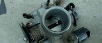
| 20 | throttle assembly; |
| 21 | TPDZ; |
| 22 | DMRV; |
| 23 | empty control; |
| 24 | Lambda probe; |
| 25 | car speed sensor; |
| 26 | DPKV; |
| 27 | DD; |
| 28 | crankshaft pulley; |
| 29 | gasoline filter; |
| 30 | petrol pump relay; |
| 31 | gasoline tank; |
| 31 | gasoline unit; |
| 32 | two-way valve; |
| 33 | gravity throttle; |
| 34 | reverse breather; |
| 35 | check valve; |
| 36 | adsorber purge throttle; |
| 37 | adsorber; |
| 38 | separator. |
Checking the ignition coil of a VAZ 2114 injector 8 valves
Checking the ignition coil of the VAZ 2114 model 2111-3705010-02 (54.37005) is carried out in the following sequence:
- Disconnect the terminal block of the ignition reel;
- Turn on the ignition, use a multimeter to measure the voltage between terminal 15 and the housing, for the ignition reel, or terminals C and D (for the ignition module) of the terminal block with a cable harness. The voltage must be at least 12 V. When the voltage does not go to the terminal block or it is less than 12 V, the battery is discharged, the power line is broken, or the controller is broken. You can verify that the ignition module is working by replacing it with a known working one. The ignition coil can be checked with an ohmmeter.
- Remove the ignition coil;
- Using a multimeter, we measure the electrical resistance between the middle terminal 15 and the bracket. The meter must indicate the absence of the short of the first winding of the solenoid on the housing. In order, we measure the electrical resistance between the middle terminal 15 and the outer terminal - 1a and 1b. The resistance of all the first windings of the bobbin must be around 0.5 Ohm. When we measure small electrical resistance sizes, about 1 Ohm, we need to take into account the internal resistance of the meter, which can be measured by short-circuiting the multimeter probes.
- Using a tester, we measure the resistance between the high-voltage terminals of the solenoid 1 and 4, and then 2 and 3. The resistance of the windings should be around 5.4 kOhm.
Possible malfunctions and ways to eliminate them
What malfunctions can occur in the electrical wiring? First of all, these are problems with the ignition system. The following symptoms can indicate such malfunctions: dips appear during acceleration, the engine loses some power without responding to pressing the gas, idle speed has become unstable. In addition, malfunctions may occur in the operation of one cylinder or several at once.
In this case, the problem is solved as follows:
- First you need to turn on the ignition and open the hood of the car.
- Next, you need to disconnect the tip of the high-voltage wire from the spark plug of cylinder 1.
- Then it needs to be brought to the engine at a distance of about 0.5 cm.
- The starter turns on, try to start the engine. At the same time, watch whether a spark jumps between the wire and the motor. The rest of the high-voltage circuits are checked in the same way. If the spark is stable, then the cause must be sought in the spark plugs. If there is no discharge, then the problem must be looked for in the circuit from the generator device to the ignition module (video author - Pavel Ksenon).
To diagnose the ignition module or coil, you will need a tester; in particular, they will need to measure the resistance in the primary and secondary windings. The received data is verified with those indicated in the service book for the car. The resistance value should be around 5.4 kOhm.
You need to check the spark with a spark plug, because the ignition module can be damaged.
As for other wiring problems:
- Incorrect operation of the generator. Problems in its operation may be associated with various components, since the unit itself consists of many units and mechanisms. To diagnose, you should first check the quality of the belt tension; if necessary, tighten it or replace it. If the belt is in order, then the generator must be removed and disassembled to determine its defect.
- Dead battery. This problem is familiar to many of our compatriots. The problem of a dead battery is solved by charging it, and if the battery life is coming to an end, the battery will have to be replaced.
- Control unit malfunctions. Such problems are usually associated with malfunctions in its operation; often the problem can be solved by flashing the device. But it’s not a fact that the firmware will help - the unit may have to be changed.
- Sensor failures. “Fours” are equipped with dozens of different sensors designed to ensure proper operation of the car’s engine. If damaged, the sensors must be replaced.
- Damage to wiring. In this case, damaged wires will need to be replaced; using electrical tape to rewind them is usually impractical.
- Damage to high voltage wires. We will tell you more about replacing them below.