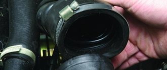
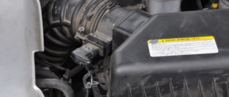
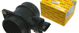
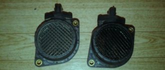
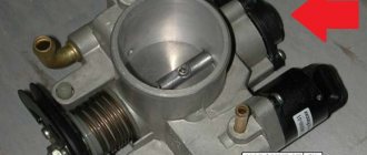
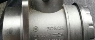
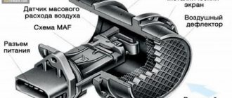
VAZ 2114 cars were equipped with several types of engines: 8 valves of 1.5 liters and 1.6 liters, as well as 16 valves of 1.6 liters. Until 2005, January 5 series ECUs were installed on the motors, then the manufacturer updated the controllers. Since 2006, these machines have been equipped with a January 7 series ECU, or imported analogues of BOSCH 7.9.7. Why do you need this information? Depending on the version of the ECU, mass air flow sensors on the VAZ 2114 were of different types. This causes some difficulties when replacing the sensor, but detailed information can be found in the car's passport.
- Air flow sensors of the 004 series were installed on early versions of cars.
- Then an updated mass air flow sensor was introduced for the VAZ 2114, series 037. The measuring channel on it was modified to reduce air flow pulsations. The new flow meter with modified characteristics is fully compatible with old ECUs with an oxygen sensor, so the replacement did not lead to changes in calibrations in the fuel-air mixture formation system.
- After switching to the January 7 series and BOSCH 7.9.7 controllers, we also had to change the air flow sensor on the VAZ 2114. The new version with index 116 is produced with an updated design. The calibration of the sensor has also been updated, so there is no backward compatibility.
The BOSCH 116 air sensor has many analogues, including the Russian Itelma and Avtel.
Information: There is an opinion among VAZ 2114 owners that the air flow sensor of the 116 series is better than the 037, and it can be replaced to increase engine output. In fact, this is not the case; the calibration of the mass air flow sensor is developed for a specific motor and is taken into account when programming the ECU.
As an example, the graph in the illustration:
Obviously, when the air flow rate is more than 100 kg per hour, the voltage that the VAZ 2114 series 116 air sensor produces changes by 0.2 volts. When the data is read by the engine controller, this makes a significant correction in the proportions of the fuel mixture.
How does the VAZ 2114 mass air flow sensor work?
A modern mass air flow sensor (also known as MAF in English) uses sensitive sensors and a special calculation algorithm to compare the resistance readings of two thermistors. One of them is a reference value, its value is constant. The second (made of platinum-iridium wire) is forcibly heated. The incoming air flow cools the wire, the resistance changes, and to equalize it with the reference, a larger heating current is required. It is the difference in current strength (in this design, voltage is measured using the Ohm's Law formula) that provides information to the ECU.
The measurement accuracy is 1/100 volt, so the slightest malfunction of the mass air flow sensor instantly affects the quality of engine operation.
Replacement instructions
On the VAZ 2114 model, the element we need is installed in the engine block, and not in the radiator block!
To check the coolant temperature thermistor with your own hands, you must first remove it. With model 2114 this is not very difficult to do. To do this you will have to:
- Remove the air filter, because the sensor itself is located on the inlet pipe of the cooling jacket of the cylinder head;
- Remove the negative charge cable from the battery;
- Drain the coolant (coolant) from the radiator. If you have good repair experience, then you can do without this item, but it is recommended for beginners to perform this item;
- Disconnect all contacts. Using a deep socket, unscrew the sensor;
- After this, you can unscrew the sensor. If the bolts are too tight, use a wrench.
Unscrewing the DTOZH should occur carefully and gradually
VAZ 2114 signs of flow meter malfunction
In addition to the indicator light on the Check Engine, there are symptoms that even an inexperienced driver will notice:
- Unstable engine operation at idle speed: the malfunction manifests itself most clearly when the engine is not warmed up. After starting, the revs fluctuate, and when the accelerator pedal is pressed sharply, the engine stalls.
- With a sharp release of gas, the speed does not decrease, but remains at around 2-3 thousand for some time.
- Even with a warm engine, there is a noticeable decrease in power. When fully loaded, a lower gear is required; the car does not pull uphill and accelerates slowly on the highway.
How to independently check the VAZ 2114 MAF sensor the “old-fashioned way”? The technique is as follows:
- you need to remember the sensations of the engine running on a familiar route with different modes: uphill, acceleration, etc.;
- turn off the engine, remove the negative terminal from the battery and disconnect the mass flow sensor connector located on the side of the brake fluid reservoir;
- start the engine and travel along the same route.
If the engine behavior has noticeably worsened, then the failure is not related to the flow meter. If you do not feel the difference, that is, the motor works the same with and without the sensor, then an in-depth check of the mass air flow sensor is required.
What's the result?
As you can see, if there are signs of problems and the first symptoms of the DMVR VAZ 2114 or another car appear, you should check the device as soon as possible for possible breakdown. In this case, you can quickly diagnose the air flow sensor with a multimeter in a regular garage.
We also recommend reading the article about what a car engine knock sensor is. From this article you will learn about the purpose, design, as well as signs of malfunction or malfunction of the engine knock sensor. Based on the readings obtained from the device, it is possible to determine the malfunction (if a breakdown is confirmed) or to exclude the mass air flow sensor from the list of possible problem elements. One way or another, it is important to understand that this sensor is actively involved in mixture formation and affects the operation of the engine as a whole.
For this reason, it is necessary to perform regular checks of the ECM, scan for errors, and also pay attention to any failures and symptoms of malfunctions of the sensors of the electronic engine control system (TSP, DPKV, etc.).
Evgeniy (auto expert) “Turn the Engine” is dedicated to one of the greatest blessings of civilization - the piston internal combustion engine. Everything about the operation, service and preventative maintenance of gasoline and diesel internal combustion engines. Useful information on engine and attachment repairs, methods and techniques for carrying out diagnostic procedures. Tuning, engine tuning and competent selection of technical fluids.
How to check the MAF sensor on a VAZ
The most reliable way is to use a diagnostic scanner (at least at the ELM-327 level). We connect to the OBD port and look at the flow meter performance indicators on the computer.
If you don’t have a scanner, you can take the basic parameters with a multimeter. To diagnose and repair the VAZ 2114 mass air flow sensor with your own hands, you need to know the pinout of the contacts.
For example, consider a contact block for a VAZ 2114: a modern 8 or 16 valve engine, BOSCH mass air flow sensor (or its equivalent) version 116.
- We don't need contact No. 1; this is an air temperature sensor.
- Contact No. 2 - 12 volt power supply. If the on-board voltage regulator malfunctions, the air flow sensor may malfunction.
- Contact No. 3 - ground.
- Contact No. 4 - power supply for the mass air flow sensor electronics, an important parameter, the voltage must be stable.
- Contact No. 5 is the same “floating” voltage with which the ECU calculates the volume of air passing through the intake manifold.
The supply voltage is checked with the block disconnected. We turn the ignition key, but do not start the engine. With respect to ground, we measure the voltage at contact No. 2 (12 volts) and contact No. 4 (5 volts). This indicates the serviceability of the ECU and the integrity of the wires and contacts.
Checking the signal voltage on pin No. 5 is carried out with the connector connected, with the ignition on (do not start the engine!).
- voltage is within 0.99-1.02 volts - the sensor is working;
- voltage within 1.03-1.05 volts - replacement will be required soon;
- more than 1.05 volts - the mass air flow sensor does not operate normally.
Checking the mass air flow sensor
Before you start experimenting, take the time to read the service manual. It describes in detail what a mass air flow sensor on a VAZ 2114 is and how to replace it.
We are looking for a sensor. Open the hood and find the air filter pipe. The mass air flow sensor is located on it, which determines the flow of air passing through the filter. I will give several options on how to check the mass air flow sensor yourself.
- Disable the sensor. Disconnect the block with wires from the connector by pressing the latch located below. Start the engine (1500 rpm or more). The controller understands the shutdown of the mass air flow sensor as an emergency condition and prepares the fuel-air mixture based on the position of the throttle valve. Try driving a short distance. If the car accelerates noticeably faster, this indicates a non-working mass air flow sensor. I would like to note that in the disabled state for ECUs Y7.2 and M7.9.7. RPM doesn't increase!
- Replacing the controller firmware. The original ECU firmware could have been replaced with an alternative one. In such a situation, we do not know which algorithm is prescribed in the case of operation in the mode discussed in the first paragraph. The throttle valve has a stop under which you need to place a thin plate (about 1 mm) to raise the speed. Then you need to disconnect the chip with the sensor. If the sensor is faulty, the engine should stall. If the engine is running, then the reason is due to the firmware features: the IAC steps are written incorrectly.
- Voltage measurement. Testing gives good results when working with Bosch sensors. You will need a multimeter. Select the DC voltage measurement mode and set the maximum value to 2 V.
The connection diagram for the VAZ 2114 looks like this:
- yellow – incoming signal;
- gray with white – power output;
- green – grounding;
- pink with black – output to the main relay.
The colors may be different, but the sequence of connectors is the same.
Next, you need to turn on the ignition with the engine off. Connect the red (positive) probe of the tester to the yellow output, and the black (negative) probe to the green. Multimeter probes are inserted along the specified wires directly through the rubber seals of the connectors without damaging the insulation. For prevention, I recommend moistening the probes with WD-40. Intermediates or needles are not recommended due to the additional error they introduce. Measure the voltage. Compare the result with the table:
| Voltage, V | State |
| 1,01 – 1,02 | Good. The sensor is almost new and will last a long time. |
| 1,02 – 1,03 | Satisfactory. The sensor is old, but works properly. |
| 1,03 – 1,04 | Bad. The resource is almost exhausted. Will have to replace it soon. |
| 1,04 – 1,05 | Deplorable. The resource has been exhausted. Suitable for use if there are no alarming symptoms. It is advisable to replace |
| 1.05 – and above | Emergency. The sensor is faulty (possibly for a long time). Replacement is required. |
A newly installed sensor gives an output voltage of 0.996–1.01 V. Over time, it increases. A higher value means a higher percentage of wear.
Voltage data from the sensors is recorded by the on-board computer and can be viewed by selecting the appropriate group of parameters.
- Inspection and cleaning. Use a Phillips screwdriver to loosen the clamp holding the air intake pipe. We remove the corrugation and check whether there are traces of oil and/or condensation inside it, as well as on the inner surface of the sensor. Normally they shouldn't be there. The sensing element of the mass air flow sensor often breaks due to dirt getting on it. This can easily be avoided by regularly replacing the air filter. Reasons for oil getting into the air flow sensor:
- the permissible oil level in the crankcase has been exceeded
- The oil separator of the ventilation system is clogged
Prevention of breakdowns and cleaning of the air flow sensor of the VAZ 2114
The flow meter sensor is located in a vulnerable place: exposure to temperature changes, moisture, dust.
Precision electronics located in the measuring channel fail when foreign objects enter.
Causes:
- untimely replacement of the air filter;
- the use of so-called “zero” filters;
- loose connection of the mass air flow sensor with the air duct flanges;
- moisture entering the air intake;
- Debris left in the ductwork or filter housing after repairs and maintenance.
How to clean the mass air flow sensor if contamination does not render it inoperable
The sensor must be removed, the protective nets removed, and blown with clean compressed air. If there is dried dirt or oil stains, washing with special means for mass air flow sensor is required. Of course, it is necessary to clean the air duct itself with the filter housing.
In most cases, such prevention brings the flow meter back to life.
What happens if the mass air flow sensor is faulty?
I’ll say right away that the mass air flow sensor is almost never repaired, but simply replaced with a new one.
- As for the device, the DMRV is not at all complicated. The sensor consists of a housing, inside of which a hot-wire anemometer is located (responsible for measuring air flow).
It is easy to damage this sensor; it can simply fail during installation, but most often it breaks due to old age.
When the mass air flow sensor is faulty, it supplies incorrect data to the control unit, due to which air does not enter the combustible mixture in the required volume.
Lada Largus does not start, the starter turns
To start a car engine, it is necessary to have a spark and a fuel mixture in the cylinders at the right time. Problems with starting the Lada Largus engine may occur if one or more elements of the vehicle systems fail. This article lists the reasons and solutions for cases when the starter turns, but the engine does not start.. Possible malfunction
| Diagnostics | Remedies | |
| There is no gasoline in the tank | On the instrument cluster the fuel level arrow is at zero. | Pour gasoline |
| Battery is low | The voltage at the battery terminals with consumers turned off is less than 12V. When trying to start the engine, a cracking noise is heard from under the hood. | Charge the battery or replace it with a new one |
| Oxidation of battery terminals or wire terminals, their fit is not tight | When you try to start the car, the voltage in the on-board network drops much more than at the battery terminals. In this case, a crash may be heard under the hood. | Clean the contacts, lubricate them with petroleum jelly and tighten the terminals |
| Unreliable connection of electrical circuits of engine control and power supply systems | Check the connections of the connectors and the reliability of the contacts in the blocks. | Fix faulty wire connections |
| Increased resistance to rotation of the crankshaft (scores on the shafts, bearing shells, cylinder-piston parts, deformation of the shafts, frozen engine oil, jammed generator, jammed coolant pump) | The crankshaft turns slowly. If the engine is started in severe frost, and the engine was working properly the day before, then most likely the engine oil has frozen. If you hear extraneous noise when starting the engine, check the free rotation of the pump and generator pulleys. | Use the recommended engine oil. Repair the engine. Replace the pump and generator. |
| Malfunction in the ignition system | Check for spark. | Check the circuits and devices of the ignition system. Replace faulty system elements. |
| HV wires are connected in the wrong order or the wire is disconnected (on K7M engine) | Inspect. | Connect the wires in the correct order |
| The timing belt is broken or the belt teeth are cut off | Open the front timing cover and check. | Replace timing belt |
| Disturbed valve timing | Check the marks on the crankshaft and camshaft pulleys. | Set the correct shaft position |
| Malfunction of the ECU (electronic engine control unit), its circuits, crankshaft position sensor or coolant temperature | Check the supply of +12V to the ECU, the sensor circuit, and the absence of damage to the sensors themselves. | Replace ECU, sensors. |
| The idle air regulator (IAC) or its circuits are faulty | Check IAC. When starting the engine, lightly press the gas pedal. If the car starts and stalls when you release the gas pedal, then the sensor is faulty. | Replace sensor |
| The fuse is blown or the main relay of the control system is faulty | Check fuse and relay. | Eliminate the cause of the blown fuse. Replace fuse and relay |
| Fuse blown, fuel pump relay. Circuit, relay or pump is faulty. | When the ignition is turned on, there is no sound of the pump running. Check the fuse. Apply voltage to the pump from the battery. | Clean contacts, replace faulty circuits, replace fuse, pump and relay. |
| The fuel filter is dirty, the water in the fuel line is frozen, the fuel line is damaged | Check the pressure in the fuel rail and the condition of the fuel lines. | Replace the filter, blow out or replace the fuel lines. |
| Insufficient pressure in the fuel rail | Check the pressure in the fuel rail, the pump strainer and the condition of the fuel lines. | Clean the filter. Replace the pump, fuel pressure regulator (RDT) |
| Faulty injectors or their power supply circuits | Check the injector windings with an ohmmeter. Check the chains for breaks. | Replace injectors, replace chains |
| Air leak into the intake tract | Inspect the joints and fittings of the hoses and clamps. During start-up, turn off the vacuum brake booster (VUT) and plug the receiver fitting. | Eliminate air leaks, replace vacuum booster |
Lada Largus starts and immediately stalls:
- Ignition coil electrical connections are loose or damaged.
- Insufficient pressure in the fuel rail.
- The connections of the intake tract parts are leaking (catalytic manifold or intake manifold receiver).
- The engine control system is faulty. Run diagnostics.
Types of mass air flow sensors, their design features and operating principle
Three types of VU meters are most widespread:
- Wire or thread.
- Film.
- Volumetric.
In the first two, the operating principle is based on obtaining information about the mass of the air flow by measuring its temperature. The latter may involve two accounting options:
- By changing the position of the slider, driven by a special blade, which is affected by the air flow passing through the device. Considering the presence of rubbing mechanisms, the level of reliability of such structures is quite low. This was the main reason for the refusal of car manufacturers from sensors of this type. For reference, here is a simplified example of the design of a volumetric flow meter.
Volumetric air flow sensor device - By counting Karman vortices. They are formed if a laminar air flow washes over an obstacle whose edges are quite sharp. The frequency of the vortices breaking off from them is directly related to the speed of air flow passing through the device.
Vortex sensor design (widely used by Mitsubishi Motors)
Designations:
- A – pressure measurement sensor to record the passage of the vortex. That is, the frequency of pressure and vortex formation will be the same, which makes it possible to measure the flow of the air mixture. At the output, using an ADC, the analog signal is converted to digital and transmitted to the ECU.
- B - special tubes that form an air flow similar in properties to laminar.
- C – bypass air ducts.
- D – column with sharp edges on which Karman vortices are formed.
- E – holes used to measure pressure.
- F – direction of air flow.
Wire sensors
Until recently, thread mass air flow sensor was the most common type of sensor installed on domestic cars of the GAZ and VAZ model range. An example of a wire flow meter design is shown below.
Design of volumetric meter IVKSH 407282.000
Designations:
- A – Electronic board.
- B – Connector for connecting the mass air flow sensor to the computer.
- C – CO adjustment.
- D – Flow meter housing.
- E – Ring.
- F – Platinum wire.
- G – Resistor for temperature compensation.
- N – Ring holder.
- I – Electronic board casing.
Operating principle and example of a functional diagram of a filament VU meter.
Having understood the design of the device, let's move on to the principle of its operation, it is based on the hot-wire method, in which a thermistor (RT), heated by the current passing through it, is placed in the air flow. Under its influence, the heat transfer changes, and, accordingly, the resistance RT, which makes it possible to calculate the volumetric flow rate of the air mixture? using King's equation:
where I is the current passing through RT and heating it to temperature T1. In this case, T2 is the ambient temperature, and K1 and K2 are constant coefficients.
Based on the above formula, you can derive the volumetric air flow rate:
An example of a functional diagram with bridge connection of thermoelements is shown below.
Typical functional diagram of a wire mass air flow sensor
Designations:
- Q - measured air flow.
- U – signal amplifier.
- RT - thermal resistance wire, usually made of platinum or tungsten filament, the thickness of which is in the range of 5.0-20.0 microns.
- RR – temperature compensator.
- R1-R3 are ordinary resistances.
When the flow velocity is close to zero, the RT is heated to a certain temperature by the current passing through it, which allows the bridge to be kept in equilibrium. As soon as the flow of the air mixture increases, the thermistor begins to cool, which leads to a change in its internal resistance, and, as a result, an imbalance in the bridge circuit. As a result of this process, a current is generated at the output of the amplifier unit, which partially passes through the temperature compensator, which leads to the release of heat and makes it possible to compensate for its loss from the flow of the air mixture and restores the balance of the bridge.
The described process allows you to calculate the flow rate of the air mixture based on the amount of current passing through the bridge. In order for the signal to be perceived by the ECU, it is converted into a digital or analog format. The first allows you to determine the flow rate by the frequency of the output voltage, the second - by its level.
This implementation has a significant drawback - a high temperature error, so many manufacturers add a thermistor similar to the main one to the design, but do not expose it to air flow.
During operation, dust or dirt deposits may accumulate on the wire thermistor; to prevent this, this element is subjected to short-term high-temperature heating. It is performed after the internal combustion engine is turned off.
Film air meters
A film MAF works on the same principle as a filament one. The main differences lie in the design. In particular, silicon crystal is used instead of platinum filament resistance wire. It is coated with several layers of platinum plating, each of which plays a specific functional role, namely:
- Temperature sensor.
- Thermal resistances (usually there are two of them).
- Heating (compensation) resistor.
Interchangeability
This issue is quite relevant, especially taking into account the cost of original products from the imported automobile industry. But it’s not so simple here; let’s give an example. In the first production models of the Gorky Automobile Plant, the injection Volgas were equipped with a BOSCH air flow sensor. Somewhat later, imported sensors and controllers replaced domestic products.
A – imported filament air flow sensor manufactured by Bosh (pbt-gf30) and its domestic analogues B – JSCB “Impuls” and C – APZ
Structurally, these products were practically no different with the exception of several design features, namely:
- The diameter of the wire used in a wirewound thermistor. Bosch products have a diameter of 0.07 mm, and domestic products have a diameter of 0.10 mm.
- The method of fastening the wire differs in the type of welding. For imported sensors this is resistance welding, for domestic products it is laser welding.
- Shape of a thread thermistor. Bosh has a U-shaped geometry, APZ produces devices with a V-shaped thread, and products from JSC Impulse are distinguished by the square shape of the thread suspension.
All the sensors given as an example were interchangeable until the Gorky Automobile Plant switched to film analogues. The reasons for the transition were described above.
Film air flow sensor Siemens for GAZ 31105
It makes no sense to give a domestic analogue to the sensor shown in the figure, since outwardly it is practically no different.
It should be noted that when switching from filament devices to film devices, most likely, it will be necessary to change the entire system, namely: the sensor itself, the connecting wire from it to the ECU, and, in fact, the controller itself. In some cases, the control can be adapted (reflashed) to work with another sensor. This problem is due to the fact that most filament flowmeters send analog signals, while film flowmeters send digital signals.
It should be noted that the first production VAZ cars with an injection engine were equipped with a filament air flow sensor (made by GM) with a digital output; examples include models 2107, 2109, 2110, etc. Now they are equipped with air flow sensor BOSCH 0 280 218 004 .
To select analogues, you can use information from official sources or thematic forums. As an example, below is a table of the interchangeability of mass air flow sensors for VAZ cars.
Compatibility table for mass air flow sensor for the VAZ model range
The presented table clearly shows that, for example, the MAF sensor 0-280-218-116 is compatible with VAZ 21124 and 21214 engines, but is not suitable for 2114, 2112 (including those with 16 valves). Accordingly, you can find information on other VAZ models (for example, Lada Granta, Kalina, Priora, 21099, 2115, Chevrolet Niva, etc.).
As a rule, there will be no problems with other brands of cars of domestic or joint production (UAZ Patriot ZMZ 409, Daewoo Lanos or Nexia), choosing a replacement mass air flow sensor for them will not be a problem, the same applies to products of the Chinese automobile industry (KIA Ceed, Spectra, Sportage etc.). But in this case, there is a high probability that the MAF pinout may not match; a soldering iron will help correct the situation.
The situation is much more complicated with European, American and Japanese cars. Therefore, if you have a Toyota, Volkswagen Passat, Subaru, Mercedes, Ford Focus, Nissan Premiere P12, Renault Megane or another European, American or Japanese car, before replacing the mass air flow sensor, you need to carefully weigh all the solution options.
If you are interested, you can search online for an epic about an attempt to replace the “native” air meter with an analogue on a Nissan Almera H16. One attempt resulted in excessive fuel consumption even at idle.
In some cases, searching for an analogue one will be justified, especially if you take into account the cost of the “native” VU meter (for example, the BMW E160 or Nissan X-Trail T30).
Checking the air sensor yourself
When a malfunction of the mass air flow sensor occurs, the air-fuel mixture becomes over-rich or lean, which immediately affects the operation of the engine and may ultimately result in engine failure.
Symptoms of a malfunctioning mass air flow sensor:
- Check Engine error appears;
- Increased fuel consumption;
- Doesn't start well when hot;
- The car began to accelerate slowly;
- Engine power lost.
The easiest way to check the mass air flow sensor on a VAZ 2114 is to disconnect the plug. If there is no signal, the engine control unit goes into emergency operation mode, determining the approximate air volume based on the throttle position. At the same time, fuel consumption increases slightly - for the VAZ 2114 it reaches 10-12 liters per 100 km. A characteristic feature is the increase in idle speed to 1500 rpm. But when using a January 7.2 or Bosch M7.9.7 controller, the idle speed does not increase due to the software features.
The normal voltage at the output of the new sensor is 0.996 - 1.01 Volts. During operation, it gradually changes and, as a rule, increases. The greater the value of this voltage, the greater the wear of the mass air flow sensor.
Here is the reference voltage in volts:
- 1.01 – 1.02 – good condition of the sensor.
- 1.02 – 1.03 – not a bad condition.
- 1.03 – 1.04 - the life of the mass air flow sensor is coming to an end.
- 1.04 – 1.05 — emergency condition.
- 1.05 and above - it’s time to replace the mass air flow sensor.
The measurement is made between the yellow and green wires. Voltage values can be displayed on the screen of some on-board computers (menu voltage from sensors, U Mass air flow sensor).
Important: the limits and fluctuations of the output voltage in at least 30% of cases for a faulty sensor will be NORMAL and will not cause the “Check” icon on the panel. That is, voltage measurements are uninformative, but the rate that it will produce in kilograms of air will correspond to the movement not where it actually is, and the ECU will interfere with the mixture based on it - hence the extra consumption!
You need to check the sensor at a service center, preferably with a proprietary scanner, which itself indicates by blinking if there is a imbalance in some parameter (in this case, air flow in kilograms), comparing it with the reference values stored in its memory.
