The ignition module on injection VAZ 2109 is deservedly considered one of the most complex electrical components. If the injectors have a module, then the carburetors have the simplest coil.
The actual, but incredibly important task of the module is the generation of high voltage current, which can reach 30 thousand watts. The current follows high-voltage wires to the spark plugs, which create a spark to ignite the air-fuel mixture.
The classic ignition coil is one of the components of the module, so the system works on a much more complex principle than on carburetors.
The procedure for connecting high-voltage wires on a VAZ 2109 (carburetor, injector)
The ignition module on injection VAZ 2109 is deservedly considered one of the most complex electrical components. If the injectors have a module, then the carburetors have the simplest coil.
The actual, but incredibly important task of the module is the generation of high voltage current, which can reach 30 thousand watts. The current follows high-voltage wires to the spark plugs, which create a spark to ignite the air-fuel mixture.
The classic ignition coil is one of the components of the module, so the system works on a much more complex principle than on carburetors.
Why are the candles flooded?
Let's first look at the reasons why the spark plugs on the injector are flooded. To do this, consider the operation of a car starter.
Thanks to the operation of its pistons and valves, a mixture of gasoline and air is supplied to the combustion chamber, which is ignited by a spark generated by the spark plugs. After ignition, the starter turns off. Thanks to ignition, the engine cylinders start working. To successfully start the engine, you need a working starter, a powerful battery and a favorable ambient temperature.
At low temperatures, gasoline does not mix well with air. It is known that frosty air contains more oxygen. An increase in oxygen content requires the supply of more gasoline. The vehicle's electronic control unit sends a signal to the fuel injectors, which increases the fuel supply. Thanks to the starter, compression is created in the cylinders and at the same time a spark is formed to ignite the fuel mixture. But since the compression does not meet the standards and the spark is weak, the incoming gasoline will flood the spark plugs, preventing the mixture from igniting. This is the reason why candles are poured in cold weather.
The formation of a spark is influenced by the following factors:
- Gasoline quality. It should not contain many impurities and dirt, as this will affect the operation of the injectors.
- Engine wear. If the engine pistons are worn out, they do not create the necessary pressure and fuel may flood the injector.
- Quality of candles.
- Quality of injector and carburetor.
- Battery power: You should monitor its charging.
If the compression is ideal, the engine will start even with minimal impulse and fuel fluid will never fill the injector. But only a new car can boast of such compression. If a car, for example, such as a VAZ, is more than three years old, gasoline fills the spark plugs on the injector more often.
How to check the ignition on an injector
First you need
o will conduct a full computer diagnostic of the system. If problems are found, the on-board computer ( ] - “computer”) is a device or system capable of performing a given, clearly defined, changeable sequence of operations
) will indicate them by way (
place, direction or the process of movement (or change); up to the scientific abstractions of this concept: Path - a system of communication along which passage or travel is carried out, along which
) red indication (
methods and techniques of observation, recording, control, characterization and assessment of the state and stages of development of various processes, objects and research systems to establish and control dependencies on
) “Check”.
Pushcha ( forest (indigenous forest, primary forest, primeval forest, pushcha) - a forest that has not been changed by human activity and natural disasters
) the whole reason for the breakdown (
toponym in Russia
) is not the electronic ignition module, but problems with the damper (
technique - a device for shutting off openings and pipelines: Damper - a valve for closing a chimney or ventilation duct Damper - a cover for closing the inlet of a furnace or
) throttle assembly (
a method of connecting and protecting linear material, for example, rope, by tying and weaving
).
Here you will need a multimeter with which you need to measure voltage ( Electrical voltage between points A and B - the ratio of the work of the electric field when transferring a test charge from point A to B to the value of this test charge
) in a system ( a set of elements that are in relationships and connections with each other, which forms a certain integrity, unity
).
After ( high-ranking diplomatic representative of his state in a foreign state (in several states concurrently) and in an international organization; official representative
) turning the key in the ignition system, indications (
testimonies are information expressed in oral responses of witnesses about circumstances relevant for consideration and resolution of the court case
) of the device must be the following:
- total voltage of the on-board circuit is 12 V;
- The throttle valve sensor readings are 0.5 V, while the throttle valve is open only 1%.
ENGINE WILL NOT START: MAIN REASONS
If you are at least a little familiar with the structure of a car, you can imagine the number of elements that affect the reliable start and good operation of the engine. Accordingly, if the car does not start, the reasons for this are sometimes difficult to find even for experienced car enthusiasts.
Let's talk not only about such trivial things as a dead battery, but also less frequent breakdowns that affect the starting of the internal combustion engine. We will separately consider gasoline (carburetor, injection) and diesel engines.
The electromotive force that powers the starter, in our case, is the battery. An insufficient level of charging, characterized by a drop in voltage at the output terminals, will not allow the starter to develop sufficient force to start the engine. There may be several reasons connecting the battery and the engine not starting:
- oxidation of contacts. You can clean oxides using sandpaper. It is also worth checking all the important connections of the circuit: ground going to the engine, starter contacts;
- self-discharge The battery may discharge due to increased current leakage. If the leak is small, it can only affect startup during periods of severe frost. Be sure to check the current leakage on your car before winter;
How to understand that the car does not start because of the battery:
- the starter only makes clicking noises or does not respond at all to turning the key;
- The starter slowly turns the engine. If the engine does not start immediately, stop trying;
- After turning the key, the lights on the instrument panel do not light up. You can turn on the headlights. If they shine very dimly, the battery is guaranteed to be dead.
STARTER POWER
If turning the key does not cause any reaction, the problem may be hidden in the starting device itself. This could be brush wear, oxidation or broken contacts, a short circuit, excessive wear on the bushings, or a malfunction of the solenoid relay.
If, after turning the key, no power comes to the starter, the problem may be in the ignition cylinder itself or in the contact group. It is a rare case when the power is cut off by the standard immobilizer or alarm system. Some cars may have a secret algorithm for disabling the immobilizer. Otherwise, you'd better contact an electrician.
SUPPLY SYSTEM
To find the answer to the question of why the car won’t start, let’s start with the fuel supply system. Malfunctions that are typical for both injection and carburetor cars:
- blown fuses (for example, fuel pump);
- banal lack of gasoline. If, by coincidence, the gasoline level sensor is lying, and the warning light for the critical amount of fuel in the tank is faulty, the car will not move. Please note that the gasoline could simply be drained overnight;
- clogged mesh in the fuel tank, which prevents debris from entering the fuel line, clogged fine filter;
- fuel pump malfunction. On injection engines, it turns on when the key is turned to the 3rd position (On), and you can hear a characteristic buzzing sound;
- clogging of the filter element, which creates a barrier to the flow of fuel.
The best way to check if fuel is flowing is to remove the fuel line hose.
Lada 2109 › Logbook › Dual-circuit ignition on the VAZ 2109
I suffered several times in the winter with starting the engine. Even when it’s not cold, but at 0 degrees, you come to start it and the car is silent. You unscrew the damp spark plugs and the battery eventually dies! With a good battery, it starts normally. As it turned out in the end, I had a contact ignition coil B- 117 from the classics. I immediately changed it to a coil from BSZ. And the car started to start and drive much better, but I didn’t stop there and decided to make a dual-circuit ignition with 2 hall sensors, 2 switches and 2 coils from the Volga ZMZ- 406
To begin with, I started assembling the distributor because it is the most basic and thinnest part of the system. I took the distributor from OKI as a basis, or an ordinary nine-wheel one. I just had it from the window lying in the garage. I completely disassembled it and started installing the second one. hall sensor directly to the standard platform at an angle of 90 degrees. Marked the approximate position of the 2nd sensor. On the platform there are risks of the approximate position of the middle of the sensor:
Drilled and tapped the threads for the bolts:
Then I carefully cut the hall sensors themselves with a metal cloth so that they do not interfere with each other. It looks something like this:
Then I modified the shaft, replaced the ignition angle advance weights with nine-shaft ones. They are smaller and lighter than those of the Oka, the photo shows Okushinsky weights! And accordingly, I also replaced the springs. The curtain remained the standard Okushinsky one, I didn’t touch it. If you make it from a nine-shaft shaft, then the curtain must also be modified sawing off two opposite ones so that it looks like in the photo:
That's all for the shaft! Next, I cut out a small piece from the distributor body itself to attach the fork of the 2nd hall sensor, drilled a hole and cut a thread for the bolt
Then I put the whole thing together. Here’s what happened:
Note: during assembly it turned out that the platform on which the hall sensors are attached from the Oka is larger than from the 2109 and it turned out to be easier to mount the sensor, so another one +, It is advisable to buy the same sensors themselves in the same store from the same batch as they are slightly different! That's all for now with the distributor!
Then I bought the rest of the necessary parts: 2 coils from the Volga ZMZ-406, a wiring harness for the BSZ 2108, an “Astro” switch, as I already had the same one
I connected the wiring according to the diagram:
Note: when connecting according to scheme 1, the tachometer will show half the revolutions. If you want to make a normal tachometer, then there is also scheme 2, you will need to solder in 2 KD213A diodes. But I did not do this and did it according to scheme 1. And don’t try to connect wires without diodes according to scheme 2; thereby you parallel both coils and it turns out that all 4 spark plugs spark at the same time when both hall sensors are triggered! Tested personally)
I made a metal mount for the coils, but it didn’t turn out very well:
And now about the most important thing: for the system to work well, you need to adjust the synchronization of the hall sensors so that the spark on all cylinders is the same advance. To do this, you need to make the opposite mark on the flywheel, this will be the TDC of the 2nd cylinder. You need to count 64 teeth along the crown from the standard mark. And Using a strobe light, align both marks from the 1st and 2nd cylinders, moving the 2nd hall sensor up and down or both sensors in the direction of the white arrows. To do this, I drilled holes with a thin drill in the sensors to move.
What are the consequences of incorrect ignition settings?
If the ignition angle is incorrectly set, the engine may behave as follows:
- Ignition is too early, which leads to detonation. This will not only reduce the comfort of using your car, but also damage the cylinder, deform the pistons and rings.
- Early detonation and a large amount of fuel in the engine lead to the formation of a large amount of white gases in the power unit. Therefore, it can be determined by the white smoke coming from the exhaust pipe after starting the car.
- There are several seconds before acceleration occurs, that is, you press the gas pedal, but the car does not react to it immediately. In such a situation, it is especially dangerous to overtake on busy roads.
- Fuel is consumed faster because the engine needs more of it.
- Engine malfunctions often occur at idle.
Most often, VAZ-2109 equipped with a carburetor are susceptible to ignition problems.
Models with an injector are easier to set up, and their owners are less likely to have to adjust the ignition.
How to check high voltage ignition wires?
Checking high-voltage ignition wires for breakdown is carried out in one of three ways.
Visual inspection is the easiest way to check and detect damage to the insulating layer of high-voltage wiring. During this check, you need to make sure that there are no cracks, cuts or noticeable abrasions on the insulation surface. A breakdown can be visually determined by sparking. To do this, in the dark, just open the hood of the car, start the engine and turn off the lights. An insulation breakdown will be noticeable to the naked eye by sparks running through the wiring.
It is often impossible to visually determine that the high-voltage ignition wire is faulty. In such cases, the old proven method is used, which consists of the following steps. The engine is started and left to idle. Next, the contacts are removed one by one from the spark plugs and then put back on. All operations must be performed with rubber gloves, without touching the car body with your body. The conductor is faulty if, when it is disconnected from the spark plug, engine operation does not change.
The next method is to use a piece of wire stripped at both ends. The check is carried out at night with the engine running. One end of the segment is connected to the car body (“ground”), the other end must be driven along the high-voltage ignition wiring. If a spark appears when carrying out insulation, there is a breakdown in this place. This way, not only the insulation is checked, but also the plastic protective caps.
Checking high-voltage ignition wires with a multimeter
Car owners usually measure voltage with a multimeter, but the same device can also determine resistance, which is very useful when checking. To measure, high-voltage ignition wires are first disconnected or completely removed. The multimeter needs to be switched to resistance measurement mode, then the probes of the device need to touch the two ends of one wire. The device will show the measured value.
If, as a result of the test, one conductor turns out to be faulty, the rest will soon fail. Therefore, replacing the high-voltage ignition wiring is done as a set, rather than as separate wires. These products most likely will not be sold to you separately.
3 Tips for Selecting High Voltage Ignition Wires
Tip #1.
Carefully study the information about the product (manufacturer, terms of use, etc.) - it should be available both on the packaging and on the product itself.
Often, on fakes, the English word “silicone” is misspelled. This phenomenon is so widespread that it was even found in one authoritative print media on automotive topics. The authors mistakenly and without verification used the word “silicon,” which actually translates as “silicon.”
Tip #2.
Evaluate the quality of caps on high-voltage electrics.
The caps are made of silicone rubber; they are necessary to protect the wiring contacts and ensure the tightness of the connections. The minimum wall thickness of the cap is 3 mm. As inspection often shows, the electrical circuit is broken precisely at the junction of the conductor terminal with the contacts of the ignition system elements. This usually happens when the wiring is removed inaccurately or when there is a poor connection with parts of the ignition system due to poor fit, oxidation processes, etc.
Tip #3.
Evaluate the quality of the highest voltage ignition wiring.
Silicone products are of the best quality today. There are several simple ways to check their quality. For example, you can expose the cable to open fire. If the insulation is of high quality, it will not be easy to melt or even ignite it. Another way to check is to twist the wire tightly. If displacement or sliding of the core relative to the cable sheath is felt, and a characteristic crunching sound occurs, it means that the adhesion of the sheath to the insulation is poor. Also try moving the insulation layer along the conductor. There should be no displacements during testing; the cable must be solid. Otherwise, when installing or dismantling the wiring, the protection may be impaired.
Useful materials about cars
here!
Source
The engine does not start in cold weather, reasons
But flooding of spark plugs, unfortunately, is not the only factor that negatively affects the engine starting procedure at low temperatures. Every car owner should know about the most common of them - familiarity with the cause of problems of this kind often allows one to prevent the very possibility of their occurrence.
Problems with flooded spark plugs can occur when purchasing and installing a low-quality product. What we can recommend to car enthusiasts is that you should not choose consumables and spare parts for your car based on thoughts of maximum savings; purchasing a quality product at a higher price can often save you from many problems that arise during operation.
A weak spark can also occur if the spark plugs are heavily contaminated with carbon deposits, but the spark produced from them is not able to ignite a cold fuel-air mixture that does not contain flammable vapors.
High-voltage wires are damaged, how to check and fix them
You can also fill the spark plugs with gasoline if the high-voltage wires are damaged. The reason is that faulty wiring can produce an uneven spark.
poor quality fuel
The quality of the fuel is a very important factor on which the evaporation process depends. Practice proves that even at normal temperatures some types of fuel do not exhibit normal combustion; there is no need to say that at subzero temperatures they will evaporate and ignite.
Experts recommend paying attention to the quality of the fuel your car is fueled with and its suitability for the season. For use in the cold season, preference should be given to gasoline with the highest octane rating allowed for your car engine.
malfunction of the power system, how to check and fix it
Difficulties in starting a cold engine can also be caused by faults in the power supply system. A negative impact is caused by clogged or worn injectors, which, as a result of existing defects, can supply the wrong amount of fuel. Naturally, such violations will cause the candles to burn out.
To eliminate the problem, it is recommended to systematically monitor the condition of the engine components and systems, and eliminate any deviations noticed in a timely manner. Maintaining the power system involves regular cleaning and adjustment to the recommended settings.
What can multiple misfires lead to?
Single misfires are only a signal to the owner of a VAZ 2114 about problems with the engine.
Numerous incidents entail the following consequences:
- As a result of misfires, unburnt fuel will enter the catalytic reduction system. Because of this, the converter will overheat and fail.
- With repeated misfires, some of the gasoline will enter the lubrication system through the walls of the idle cylinder. Oil diluted with gasoline will lose its properties and will not be able to provide high-quality lubrication of loaded engine elements.
- All these factors can lead to engine failure and the need for expensive repairs.
Engine workflow through cylinders
The cylinders are activated as follows:
- In the first there is an upward movement. The gases expand and the mixture of air and fuel burns.
- In the third, to carry out the compression procedure, the piston rises.
- In the fourth, “injection” occurs - the piston moves down and at the same time a mixture of air and gasoline enters the cylinder.
- In the second cylinder, the piston rises and takes the upper position so that gases escape through the valve system. After which the exhaust gases are removed from the power unit.
Based on the principle of operation of the cylinders, their activation diagram looks like this: 1-3-4-2. It is important to connect them correctly so that the cylinders work in that order.
Signs of malfunction of high-voltage ignition wires
Evidence that the ignition cables have become unusable are the following signs:
- difficulty starting the engine, especially in wet weather;
- At medium and high speeds, unstable engine operation is noted;
- the engine does not develop full power;
- increased fuel consumption is observed.
As a rule, when there is severe wear on the wire insulation, many microcracks appear, due to which current leakage occurs. As a result, the wire is not able to transmit to the spark plug a current that is sufficient in magnitude for its normal operation. This significantly increases the spark generation time and interferes with the correct operation of the engine cylinders.
Quite often there are cases when wires are damaged as a result of contact with any engine elements. Situations of loss of cap tightness are also possible, and as a result - oxidation of contacts and current leakage. Regular cleaning of contacts is a mandatory procedure, especially when operating a vehicle in difficult climatic conditions.
How can a car owner check the wires for leaks? In fact, everything is very simple: in a dark garage, open the hood and start the engine. Leak areas will glow quite brightly in blue. There is a slightly different method: instead of a spark plug, a spark gap is installed (two electrodes in one housing) and the energy supplied to the spark plug is controlled using it.
In order to increase the durability of the insulation, it is recommended to monitor and constantly keep it clean. The contacts between the spark plugs and each wire are also subject to constant checking and cleaning.
High voltage wires
Spark plugs
The VAZ-2109 ignition system uses spark plugs A17DVR, A17DVRM where:
The importance of spark plugs in the overall operation of a car's ignition system cannot be underestimated. POPULAR WITH READERS: Prices and configurations of the cross-version LADA XRay Cross have been announced
POPULAR WITH READERS: Prices and configurations of the cross-version LADA XRay Cross have been announced
It’s not for nothing that many drivers, out of habit that remains from past times, carry a spare set of spark plugs with them. This may be unnecessary, since modern candles are quite reliable, but breaking any habit is not so easy, even this one.
Read here what to carry in your trunk...
During operation, the spark plug endures huge ranges of loads, which are expressed in high operating temperatures, mechanical, electrical and chemical influences.
For example, in the combustion chamber, the operating temperature can vary from 60 to 2800 degrees, pressure up to 10 MPa, voltage up to 30 kV, not to mention the constant chemical effect on the spark plug from combustion products.
During the operation of the spark plug, carbon deposits form in all its areas, which leads to loss of current, and the gap between the contacts in the spark plug can increase from 0.012 to 0.016 mm or more for every 1000 km of travel.
Using the spark plug, you can simply diagnose the condition of the engine, but as a rule, we pay attention to the spark plugs only when malfunctions begin in the engine or when it’s time for scheduled maintenance. The engine is in good condition if:
The engine is in good condition if:
- No phlegm on the threads;
- A thin layer of soot on a dark rim;
- All electrodes are light grey, light brown, whitish or light yellow.
Signs of engine problems:
- There are oil or gasoline residues on the threads;
- There is loose black carbon deposits with spots on the rim;
- All electrodes are dark brown with spots;
- The candle is wet with dark soot;
- A dark rim on the outer part of the candle (if the candle is not sealed).
The use of only spark plugs of the A17DVR, A17DVRM brands in the ignition system of the VAZ 2109 is not a panacea, of course there are alternative options, but you need to be able to choose the right spark plugs for your car, and for this you should familiarize yourself with these concepts
- What are hot and cold spark plugs and what engines are they used on?
- What is heat number;
- What is the compression ratio and a number of other indicators.
Therefore, if you do not understand these issues, then before replacing the spark plugs recommended by the manufacturer with others, seek recommendations from specialists.
Features of connecting high-voltage wires to the VAZ 2114
High-voltage ignition wires of the VAZ 2114 are part of the ignition system, through which an electrical impulse is transmitted from the module to the spark plugs. When the current hits the spark plugs, the fuel mixture ignites in the combustion cylinders, which gives rise to a new stroke of the engine.
BB wires must be of high quality
The design of the GDP, unlike conventional wires, is quite complex. In addition to the conductive core (which is made of copper) and protective insulation, they have metal tips and plastic protective caps.
Metal tips act as contacts; they fit into the sockets on the spark plugs and the ignition module. The durability of the GDP directly depends on how well the tips are made. When purchasing, be sure to check the strength of their attachment to the wire.
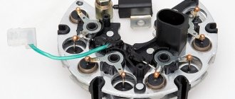
Distributor device with Hall sensor
On the VAZ-2109, the manufacturer installed a contactless type distributor equipped with a Hall sensor. It is four-spark, additionally equipped with a centrifugal and vacuum corrector.
In addition to correctors, the device has other elements that contribute to proper operation. Thus, the distributor is equipped with a special plastic screen. It is necessary to protect the working surfaces of the mechanism from dust and dirt. The slider mounted on the distributor rotor has a constant resistance of about 1 kOhm. In addition, the design includes thrust washers, lock washers and O-rings. The body is one-piece, aluminum.
Wiring replacement process
Before the VAZ 2114 armored wires are replaced, it is necessary to remove the old cables. To do this, you should: 1. Turn off the engine ignition. 2. Open the car hood. 3. Remove the old wiring leading to the engine and ignition unit. To maintain the order of connecting high-voltage wires of the VAZ 2114, you must be guided by the following diagram:
Cylinders are numbered from left to right. In the module, the internal ignition cylinder 1 is located on the lower left side. The second and third cylinders are located in the left and right compartments, respectively. The output of the fourth cylinder is located at the bottom in the right compartment.
BTSZ device
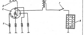
The ignition system of the VAZ 2109 consists of:
- Switch 3620.3734;
- Spark plugs A17DVR;
- Distributor sensor 40.3706;
- Ignition coils 27.3705;
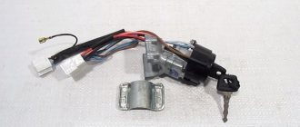
- Ignition switch;
- — A locking device that prevents the starter from being turned on again until the ignition is completely turned off;
- — Locking and anti-theft device.
Design features and operating principle
- The operating principle of the VAZ 2109 ignition system is based on the Hall effect.
- The sensor-distributor shaft receives torque from the engine camshaft and is located horizontally.
- Spontaneous shutdown of the ignition system occurs 2-8 seconds after turning the ignition key to the extreme left position and the engine is turned off.
- During the operation of the SZ, the switched current is equalized in the case when the voltage in the network varies from 6 to 18 V.
- At low engine operating frequencies, thanks to a special system built into the switch, the time of accumulation of electricity in the ignition coil is regulated, and the current is limited.
The ignition system of the VAZ 2109 operates at a voltage of up to 26 kilovolts, the duration of the spark discharge varies in the range of 1.6-2.0 ms and during this time 35 - 50 MJ of energy is released.
How to check high voltage wires
Finding high-voltage wires under the hood is not difficult, and diagnosing them is not fraught with any difficulties. There are three ways to check high-voltage wires, each of which allows you to determine whether there is a breakdown in them.
Visual diagnostics
The easiest way to check spark plug wires for insulation damage is to visually inspect them. It is necessary to carefully check that there are no cracks, cuts or severe abrasions across the insulation area.
Another way to visually check spark plug wires is to observe their operation at night. It is necessary to open the hood of the car at night, start the engine, turn off the headlights and watch the high-voltage wires. If they have strong insulation breakdowns, in the dark the “crickets” will be visible to the naked eye.
This is interesting: Reasons why there is no spark on a 4T scooter
Wire check
To check the spark plug wires, an ordinary wire with stripped ends on both sides can be used. In the dark, with the engine running, it is necessary to short-circuit one part of the wire to ground (car body), and run the other part along high-voltage wires in search of a place where the stripped tip will begin to produce a spark.
It is important to check not only the insulating material around the conductor, but also the plastic caps
Diagnostics with a multimeter
A multimeter in automotive diagnostics is most often used as a voltmeter, but it also has another useful function - the ability to measure resistance. To take measurements, you must completely remove the high-voltage wires (or disconnect one wire on both sides). Next, with the probes of the device set to ohmmeter mode, you should touch both sides of the wire, as a result of which the multimeter will display information about the resistance.
The resistance of serviceable high-voltage wires is up to 10 kOhm. At the same time, it can vary practically from zero. This depends on the type of wires themselves, the insulation used in them, the length, the presence of microdamages, and so on.
How to check the fuel system
It often happens in very humid weather that the fuel supply mechanisms break down. Water can seep into any crack and get onto the connectors of the injectors that spray gasoline in the combustion chamber, and into the gas tank through the O-ring of its neck cap. And even through the gasket of a submersible pump, which is installed directly into the tank.
Injectors are the easiest to diagnose. They are unscrewed and pulled out of the cylinder head. By pointing the injector nozzles away from the car, turn on the ignition for a couple of seconds, the pump starts working, and the nozzles should begin to spray gasoline. If spraying occurs, then everything is in order. It is worth checking the condition of the gasoline.
To do this check, unscrew the supply tube to the injector rail and, using a small, clean container, point the end of the tube into it. After turning on the pump for a few seconds, you need to assess the condition of the gasoline in the container for the presence of water. The appearance of water in the fuel means that the tank needs to be repaired. The flammable mixture is drained from it, allowed to dry completely and filled with clean fuel.
OPERATIONAL CHECK
To accurately determine whether it is time to change the high-voltage wires of the VAZ, you need to check their performance with a multimeter.
This operation will take you no more than 15 minutes:
- Turn off the ignition;
- We remove the wires: disconnect the first end from the ignition module, the second from the cylinder;
- We switch the tester to ohmmeter mode and connect the multimeter probes to the wire contacts.
If the high-voltage wires on the VAZ 2114 are in normal technical condition, the multimeter will show a resistance within the value indicated on the wire insulation; if the readings are different, the armored wires on the VAZ 2114 need to be replaced. The process must be repeated on each wire in turn.
If the test shows disappointing results, there is a possibility that the problem of increased resistance lies in oxidized contacts. In this case, you can try to revive the VVP by wiping the contacts with VD-40 or carburetor cleaning fluid.
What can be changed in the electrical circuit
Let's figure out what exactly car owners undergo alterations.
Moreover, we will indicate only those alterations that are not prohibited by the manufacturer and current regulations:
- Installation of a new instrument panel;
- Alteration of internal (interior) lighting;
- Installation of additional turn signal indicators in the rear view mirrors;
- Installation of additional headlights (fog lights);
- Installation of an acoustic and multimedia system;
- Immobilizer installation.
For reference: the visual differences between the standard panel and the “high” one are that the radio compartment is moved to the level of the dashboard. Accordingly, the wiring on the VAZ 2109 under the instrument panel must be replaced.
Interior modifications
Many owners come to mind with the desire to improve the lighting in the car interior.
Arrangement of high-voltage ignition wires
High-voltage wires consist of a conductive core, a protective layer (also called insulation), special metal contacts and caps. There are several types of high-voltage wires. The usual (cheap) type of wire is one that consists of stranded wire with thick insulation. The resistance of such high-voltage wires is zero, which does not properly affect the operation of the ignition coil.
The second expensive type of high-voltage wires consists of a thread placed in the center covered with ferroplast on top, which is wound with iron-nickel wire. This type of high voltage wire has sufficient resistance, which greatly reduces radio interference and is suitable for the normal operation of the ignition coil. To further reduce radio interference, increased insulation is used. It should be noted that the correct order of connecting high-voltage wires plays an important role in the normal operation of the engine ignition system.
Insulation of high-voltage wires is designed to prevent electrical leakage and isolate the conductor from moisture and other contaminants. Insulation can be single-layer or multi-layer.
Metal contacts of high-voltage wires (tips) are used to establish a connection between the wire cores and the spark plug sockets and distributor.
Requirements for high-voltage wire lugs:
- Ensuring reliable contact with the wire veins;
- Reliable and durable fastenings;
- Sufficient corrosion resistance and high-quality insulation.
Caps for high-voltage wires ensure tightness of contact connections, protecting the connection points from moisture and current leakage.
The procedure for connecting high-voltage wires: checking and replacing high-voltage wires
To check the wire, you will need a multimeter tester, with the help of which you can measure the resistance of the wires - which should be no more than 20 kOhm (usually the wire of 1 cylinder has a resistance of up to 10 kOhm). If the wire resistance is higher than 20 Kom, it must be replaced. Carefully inspect the wires for wear. When installing wires, do not allow kinks, distortions or tension on the wires.
Malfunctions of high-voltage wires
The main malfunctions of high-voltage wires include electrical circuit breakage and current leakage.
Causes of the malfunction: careless removal of the wire, poor connection, oxidation and subsequent destruction of the high voltage wire core. Current leakage occurs due to moisture entering the connection. At sub-zero temperatures, the insulation of high-voltage wires becomes rigid and the risk of damage to the wires increases. The service life also affects the wear of high-voltage wires. After all, when the engine is running, vibration occurs, which affects all connections, simply loosening them. The connections are also affected by the increased temperature that comes from the engine.
Recommendations for caring for high-voltage wires:
Periodically check high-voltage wires for damage. Check the reliability of connections between the tip and the elements of the ignition system;
Carry out all manipulations to remove and install high-voltage wires carefully and carefully, without tugging at the insulation.
Do-it-yourself distributor repair
Before you repair a faulty distributor, you will need a VAZ distributor repair kit. You can find it at any auto store. The dismantling and installation procedure is described below (the author of the video is Dmitry Slesarenko).
Removal and installation
If the distributor fails, it can either be repaired or replaced with a new one. Here everything depends on the specific breakdown.
The sequence of removal and installation steps is as follows:
- First you need to de-energize the car's electrical circuit; to do this, disconnect the battery.
- After this, you need to disconnect the wires from the distribution unit. Having done this, also disconnect the vacuum pipe that goes to the corrector.
- Next you need to find the cable holder that goes to the throttle actuator. This cable must be removed.
- Dismantle the bracket that secures the wires, along with them and the studs. To do this you will need to unscrew the nut. Be careful - there is a washer under the nut, you cannot lose it.
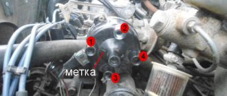
- Having done this, you need to install marks on the housing of the distribution unit and the drive of the auxiliary elements. If you do not put the marks, then after further installation of the mechanism in place you will have to set and adjust the ignition again.
- On the distributor body you can see the connector to which the harness with high-voltage wires is connected. You need to press out the fastening, use a screwdriver for this, and remove the wires. Then remove the rubber plug, which is located in the clutch housing itself.
- Rotate the crankshaft with your own hands until the piston of cylinder 1 reaches TDC. The mark on the flywheel in the hole must coincide with the middle mark located on the housing scale.
- After this, you can unscrew the nuts that secure the distributor and dismantle it.
- As for further installation, it is carried out in the reverse order. When installing the device in place, you must make sure that the distributor shaft is turned so that the outer contact of the runner is located against the terminal that corresponds to 1 cylinder of the internal combustion engine. The terminal itself is located on the cover.
- When installing, combine the risks as we reported above. If you have difficulty installing the ignition, use this article.
Sorry, there are no surveys available at this time.
How does a distributor work?
The distributor design is based on a rotating shaft (the so-called roller), driven by the engine camshaft. Devices and elements of the distributor are mounted on the shaft, which operate from the rotation of the shaft.
Operating principle of the distributor (ignition sensor-distributor) VAZ 2108, 2109, 21099
The operating principle of the distributor includes the operation of all its elements.
The rotor (runner) rotates and distributes the spark over the side contacts in the distributor cover. Then it goes through high-voltage wires to the spark plugs. The spark is supplied to the slider itself from the ignition coil through a movable central contact in the cover.
The Hall sensor has a gap through which a rotating screen with four teeth and four slots passes. When a screen slot passes through the gap of the sensor, a pulse is sent to the ignition system switch, which is a signal to supply a spark.
The centrifugal ignition timing regulator increases the ignition timing when the distributor shaft rotation speed increases due to the divergence of its weights and the impact on the Hall sensor screen, which allows the fuel mixture to burn in a timely manner and with maximum efficiency.
Operating principle of a centrifugal regulator
The vacuum ignition timing regulator, due to the vacuum transmitted to its housing, also affects the Hall sensor screen and increases the ignition timing angle when the load on the engine increases (the greater the load, the greater the vacuum, the greater the angle).
Vacuum ignition timing regulator for VAZ 2108, 2109, 21099 cars
By changing the position of the distributor relative to the scale on the housing of the auxiliary units, you can manually adjust the ignition timing up or down.
Adjusting the angle with a distributor, VAZ 2108 car
Notes and additions
— Two different ignition distributors (distributors) with different covers were installed on VAZ 2108, 2109, 21099 cars. For engines 2108 and 21083 this is distributor 40.3706, for 21081 – 40.3706-01. They are structurally identical, but differ in the characteristics of the vacuum and centrifugal ignition timing regulators. The distributor cover 40.3706-01, for engine 21081, is marked with yellow paint, the distributor 40.3706 is red. There are no differences between them, they are interchangeable.
Purpose of the distributor cover
The design of the ignition distributor cap (aka distributor) has remained and remains virtually unchanged throughout the entire history of the use of this device as part of the ignition system of gasoline engines:
- On most ignition caps, the contacts for the spark plug wires are marked with numbers that correspond to the serial numbers of the corresponding cylinders
- In addition to protecting the distributor mechanism itself from moisture and dirt, it also serves the purpose of alternating the supply of high-voltage current from the ignition coil winding through high-voltage wires to the spark plugs
- It is because of this narrow specialization that the distributor cap has undergone almost minimal changes along the evolution of all car systems
Let's look at the design and operating principle of this much-needed part.
The distributor cap is a molded part made of non-electrically conductive material (insulator) that has the following device:
- Metal contacts are pressed into this part - these are the side and central electrodes
- The number of side electrodes strictly corresponds to the number of engine spark plugs (but not cylinders, do not forget that there are engines in which there is more than one spark plug for each individual cylinder); the distributor cover on the VAZ 2109 in our case has four side electrodes
- A high-voltage (armor) wire coming from the ignition coil is connected to the central electrode from the outside
- To the side electrodes - high-voltage (armor) wires going to the spark plugs
- Inside the cover itself there is a central contact equipped with a terminal that has a spring-loaded contact element (“carbon”), which transmits voltage to the central (main) contact of the distributor rotor (ignition distributor)
Schematic design of the lid
- When installing the cover on the distributor body, it is important to take into account not only the order in which the armored wires are connected, but also the orientation of the cover in relation to the “nose” of the runner is also important
- The ignition distributor cap is attached to the distributor body using latches or screws (the distributor cap on the VAZ 2109 is secured with screws)
- To prevent the formation of condensation under the lid, it has a special ventilation hole
Features of device operation
The “sore spot” of the distributor cover and rotor (ignition distributor) are the electrodes pressed into it:
- The reason is simple - there is no direct contact between these electrodes and the central electrode on the slider, so a spark jumps when they approach through the air, which causes the side electrodes to char rather quickly
- In order for the distributor cap to function reliably, it must be kept clean both outside and inside.
- It is necessary to periodically check the condition of the electrodes contained in it.
- If carbon deposits or oxides appear on them, clean the contacts of the VAZ 2109 distributor cover with a flat file
- It is not recommended to use sandpaper due to the high probability of abrasive particles getting into the distributor mechanism
- In addition, you should carefully monitor the external condition and mobility of the central contact (“coal”) of the cap electrode
Distributor cap as an anti-theft device
Due to the increasing number of car thefts, some “savvy” owners began to use the distributor cap as an additional anti-theft device:
- By removing the cover, which can be removed quite easily, you will make it more difficult for a thief who wants to steal your car.
- Firstly, the car simply won’t start without it.
- Secondly, even if he finds or has a cap with him, having removed the armored wires, you did not mark their connection order, connecting at random it is difficult to quickly achieve correct operation of the ignition
VAZ 2114 engine repair
During the operation of the internal combustion engine on a car, various failures and malfunctions may occur, which can be eliminated by self-repair or with the involvement of specialists. The need for a major overhaul of the power propulsion system, with its proper operation, arises when the mileage reaches 150,000 km. In this case, a VAZ 2114 engine overhaul is needed.
Before you begin disassembling the engine, you need to drain the oil and coolant, and then wash the entire unit. Be sure to remove all attachments so as not to damage them during reassembly. Disconnect all pipes through which gasoline is supplied. Remove all systems and components related to the air supply, remove the air supply and exhaust hoses and pipes. Remove the cooling system pipes and crankcase breather. Don't forget to disconnect the throttle pipe. Remove the receiver, as well as the pipeline mounting bracket and the fuel rail, remove the injectors with regulators. Remove the wires with the ignition module and knock sensor. Unscrew the spark plugs. After this, unscrew all sensors. Remove the generator by first removing the tension belt. With the generator, remove all brackets and strips necessary for its installation and adjustment. Block the flywheel and remove the generator pulley. Remove the camshaft drive with the cover, tension mechanism and pulley. Unscrew the pump, remove the exhaust manifold and thermostat. Disconnect the oil filter and oil sump, then remove the oil pump. In order to remove the piston group, you need to unscrew the nuts from the connecting rod bolts and remove the cover. Since the flywheel is blocked, you need to unscrew its fastenings with the flange and remove the flywheel disk. Remove the caps from the main bearings along with the lower bearings. Carefully pull out the crankshaft
It must be handled very carefully to prevent damage and scratches. Remove the upper liners and thrust half-rings.
Many motorists, especially beginners who have just purchased a VAZ-2114, have wondered how the 8-valve injection engine that is installed on this car works. This article will discuss the design of the motor, its main characteristics, as well as dismantling and repair features. This information will be very useful for beginners and those who do not know how the main power unit works.
Video about the VAZ-2114 engine
Typical faults
First, let's look at the symptoms that indicate a faulty distributor:
- the vehicle begins to jerk for no reason while driving;
- the engine stopped starting normally;
- when you press the gas pedal and increase the speed, detonation begins - the knocking of the so-called fingers;
- the dynamics of the car have deteriorated significantly - it takes much longer to gain speed;
- Gasoline consumption increases.
Repair of the VAZ distributor is carried out in case of such breakdowns:
- The device slider is burnt out;
- the reason is the distributor cover, on which the contacts have burned out;
- the Hall sensor has broken or its bearing element has become loose, and the bearing could jam;
- cracks or other mechanical damage may appear on the cover;
- there is no contact of the Hall sensor connector;
- engine fluid gets into the device, in this case it is necessary to replace the distributor oil seal.
CONNECTION FEATURES
The order of connecting high-voltage wires must be strictly sequential, since each cylinder of the engine corresponds to a specific socket on the ignition module. Considering that there is a numbering of the sockets on the ignition module body, the risk of confusing anything is minimal.
The procedure for connecting high-voltage wires of the VAZ 2114 injection type depends on the year of manufacture of your car. Fourteeners before 2004 had 4-pin ignition modules installed, and cars after 2004 had 3-pin coils.
The connection diagram for VAZ 2114 high-voltage wires to the ignition module (until 2004) is as follows:
Connection diagram for VAZ-2114 with ignition coils (after 2004):
In the pictures you can see the numbers of the landing slots. Each number must have a corresponding cylinder connected to it (cylinder numbering is counted from left to right).
To correctly install high-voltage wires on the VAZ 2114, follow the following algorithm of actions:
- Turn off the ignition. Open the hood and remove the power terminals from the battery;
- We remove the old GDPs from the mounting sockets on the module and cylinders;
- We remember the location of the high-voltage wires of the VAZ 2114 and connect new GDPs according to the diagram. Before replacing, it would not be amiss to draw this very diagram by hand on paper so as not to confuse anything;
- We connect power to the battery and, to check whether we did everything correctly, start the engine.
When installing the wiring, do not try to connect individual air intakes to each other with plastic clamps; to do this, you must use the comb holder that comes with them. A thin clamp can easily wear through the insulating coating. Also make sure that the GDP does not bend.
Connecting armored wires on VAZ 2115 and 2113 is carried out in a similar way.
Engine compartment modifications
In addition to replacing the power unit after it has exhausted its life, there are many components in the engine compartment whose wiring also needs to be replaced:
- high-voltage wires from the ignition unit;
- wiring of various control sensors;
- battery power cables (connections are most susceptible to corrosion).
Numerous sensors in the engine compartment require special monitoring:
- Coolant temperature sensor - if the electrical wiring is faulty, the driver will not notice overheating of the power unit;
- Brake fluid level sensor in the expansion tank - a leak or low level can lead to brake system failure;
- ABC system sensors - oxidation of contacts or disruption of wiring integrity can lead to system failure;
- Exhaust gas sensor - based on its readings, the electronic unit “prepares” the fuel-air mixture. If the sensor does not work, gasoline consumption will increase.
A useful addition to the functionality of the car is the acquisition of a modern anti-theft system.
Installing a modern alarm system is a special topic, since its work affects several main components and systems of a VAZ family car:
- General electrical system;
- Supply system;
- Sound and light circuit and actuators (side lights, headlights, sound signals);
- Standard immobilizer.
Advice: often manufacturers of alarm systems accompany the installation process with video and photo materials for each specific model of a particular family of cars. Before starting installation, you should read them carefully.
General alterations
Installing additional fog lights is a general modification because:
- Affects equipment in the engine compartment;
- Interferes with the instrument panel inside the cabin;
- Connects to the vehicle's standard power supply system;
- Attached to the power body.
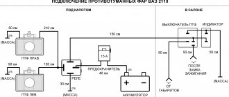
To install and connect fog lights, you will need a wiring diagram for the VAZ 2109, because the package includes:
- Connecting wires;
- Terminal blocks;
- Switching relay;
- Actuators (buttons);
- A backlight lamp (or LED) indicating the status of lighting fixtures.
They break through armored wires, what does it affect?
Basic malfunctions of ignition wires
The main faults of the wires include electrical circuit breakage and current leakage.
An electrical circuit break usually occurs at the point where the metal contact of the wire is connected to the conductor, as well as to other elements of the ignition system. This happens when the wire is removed, when the wire is destroyed or oxidized, as well as when there is poor contact with the terminals of the elements in the ignition system. The place where the connections are broken heats up and sparks, which aggravates the situation and causes the core or metal contacts to burn out. Electricity leaks through contaminated wires, ignition coil, distributor cap, spark plugs, caps and damaged insulation, which contributes to the deterioration of their dielectric properties during operation.
Low temperatures increase the rigidity of high-voltage wires, which increases the possibility of damage to their insulating layer and caps. Constant vibrations from a running engine loosen the contact points, which leads to their deterioration. Rising temperatures have the greatest impact on the spark plug caps, as they are located closest to the heated engine parts. In addition, very often they become unusable when removed. Over time, dirt, dust, moisture, and secretions of fuels and lubricants, which serve as current conductors, collect on the elements of the ignition system. Leaks become even more noticeable when the insulation is damaged and in humid weather. In addition, dirt and moisture increase microcracks.
How to choose high-voltage wires - what to look for
When choosing high-voltage wires, you need to focus on the recommendations of their manufacturer, as well as the engine manufacturer. First of all, you need to study everything that is written on the package. It would be good if it indicated in Russian the models of cars or engines for which the wires were intended.
Do not rush to buy them if the packaging does not contain the manufacturer’s “coordinates” and instructions for their use. Spelling errors in captions are also a warning. There is a very common mistake in the word silicon. It should be taken into account that the international standard ISO 3808 applies to wires for cars, so all inscriptions are determined by the manufacturer.
Wire resistance is measured using a tester. But this method is not acceptable for wires with a current-carrying core wrapped around them, since due to their design features, the resistance value on the motor changes.
The level of interference from the vehicle's electrical equipment and from high-voltage wires is assessed using a car radio. The verification procedure can be seen in the diagram.
The insulation of the wires should not allow breakdown, therefore, when choosing it, take into account the maximum voltage that can be in the ignition system. The insulation and caps must be made of a material that retains its properties over large temperature differences, for example, silicone.
Many car enthusiasts consider car wires to be of secondary importance, and specialized publications do not pay due attention to them. The sellers also cannot say anything intelligible. Nevertheless, this detail is important and deserves attention, both when choosing and operating a car.
Types of sanitary protection
The ignition system serves to ignite the air-fuel mixture located in the engine cylinders at the required moment.
The applied protection systems can be divided into three main types:
- Contact;
- Contactless;
- Contact transistor.
The first and third types are not of particular interest to us, since the VAZ 2109 uses a contactless or contactless transistor system.
https://youtube.com/watch?v=Ud-nuLSxwvk
The use of such schemes began in the mid-80s of the last century. Over time, engineers have been able to improve efficiency, performance and reliability.
BSZ began to use non-contact sensors instead of a breaker, which make it possible to instantly determine the speed of rotation of the crankshaft and the angle of its position.
Operating principle
The operating principle of the ignition system installed on the VAZ 2109 is as follows:
- The crankshaft position sensor performs its main tasks, sending a signal to the controllers;
- The controller processes the received information and calculates the sequence of switching on the ignition coils;
- The coil creates two sparks - igniting and idle.
The dry spark method involves creating sparks simultaneously in two spark plugs. One is igniting, and the second is idle, because it beats in time with the release of exhaust gases on the other spark plug. Thus, the cylinders where sparks are generated simultaneously create pairs - cylinders 1 and 4 and cylinders 2 and 3.
Coil
Main advantages
The ignition system used for nines has good reliability indicators, although it produces energy up to 50 kJ, and the breakdown voltage can sometimes reach 30 kV or more. BSZ is valued for its high efficiency.
There are several main advantages that characterize contactless ignition systems.
| Advantages | Peculiarities |
| SZ works with a Hall sensor | Because of this, the spark energy parameters are not affected by the voltage in the electrical network or the frequency of the engine. This is due to the fact that the time period of energy concentration in the ignition coil is always constant. This ensures high efficiency of the circuit |
| There is no mechanical interaction between contacts | This ensures there is no contamination or burning of contacts, so there is no need to clean them |
| No need to adjust the position of the contacts | This can be explained simply - they are not in the SZ VAZ 2109 |
| Minimal mechanical interactions between parts | This factor contributes to the absence of rotor vibrations, resonance, and uneven spark distribution across the spark plugs |
| The energy in the candles is constantly increased | It can reach 50 J, which allows you to avoid failures when igniting the air-fuel mixture in the cylinders. This is especially noticeable when accelerating a car. |
| Cost-effective and environmentally friendly | The use of the new SZ made it possible to improve fuel economy by approximately 5 percent, as well as reduce CO emissions by 20 percent |
| Stable cold engine start | Even if the battery is discharged to 6V, you can still start the engine without problems. This makes BSZ significantly different from other ignition systems that cannot boast of such stability. |
Scheme
Operating procedure for an inline 4 cylinder engine
The operating order of a 4-cylinder engine is designated as X―X―X―X where X is the cylinder numbers. This designation shows the sequence of alternating cycle strokes in the cylinders.
The order of operation of the cylinders depends on the angles between the crankshaft cranks, on the design of the gas distribution mechanism, and the ignition system of the gasoline power unit. In a diesel engine, the fuel injection pump takes the place of the ignition system in this sequence.
Of course, you don’t need to know this to drive a car.
It is necessary to know the operating order of the cylinders when adjusting valve clearances, changing the timing belt or setting the ignition. And when replacing high voltage wires, the concept of the order of operating cycles will not be superfluous.
Duty cycle
Depending on the number of strokes that make up the operating cycle, internal combustion engines are divided into two-stroke and four-stroke. Two-stroke engines are not used in modern cars; they are used only on motorcycles and as starters for tractor power units. The cycle of a four-stroke gasoline internal combustion engine includes the following strokes:
- Intake - the exhaust valve is closed, the intake valve is open, the piston moves downward, and the air-fuel mixture is sucked in.
- Compression - all valves are closed and the piston moves upward, compressing the air-fuel mixture.
- Working stroke - the valves remain closed; at the end of the previous stroke, a spark ignites the compressed mixture. The piston, under the influence of gas pressure from the burnt mixture, goes down, rotating the crankshaft.
- Exhaust - at the end of the previous stroke, the exhaust valve opens. The piston, pushed by the crankshaft, moves upward and displaces combustion products into the exhaust manifold.
The diesel cycle is different in that during intake only air is sucked in. Fuel is injected under pressure after air compression, and ignition occurs from contact of the diesel engine with air heated by compression.
Numbering
The cylinder numbering of an in-line engine starts with the one furthest from the gearbox. In other words, from the timing belt or chain side.
Sequence of work
On the crankshaft of an in-line 4-cylinder internal combustion engine, the cranks of the first and last cylinder are located at an angle of 180° to each other. And at an angle of 90° to the cranks of the middle cylinders. Therefore, to ensure the optimal angle of application of driving forces to the cranks of such a crankshaft, the order of operation of the cylinders is 1-3-4-2, as in VAZ and Moskvich internal combustion engines, or 1-2-4-3, as in GAZ engines.
Alternation of measures 1-3-4-2
It is impossible to guess the order of operation of the engine cylinders by external signs. You should read about this in the manufacturer's manuals. The easiest way to find out the operating order of the engine cylinders is in the repair manual for your car.
crank mechanism
- The flywheel maintains the inertia of the crankshaft to move the pistons from the upper or lower extreme positions, as well as to rotate it more evenly.
- The crankshaft converts the linear movement of the pistons into rotation and transmits it through the clutch mechanism to the gearbox input shaft.
- The connecting rod transmits the force applied by the piston to the crankshaft.
- The piston pin creates a hinge connection between the connecting rod and the piston. Manufactured from alloyed high carbon steel with surface hardening. Essentially it is a thick-walled tube with a polished outer surface. There are two types: floating or fixed. The floaters move freely in the piston bosses and in the bushing pressed into the connecting rod head. The finger does not fall out of this design thanks to the locking rings installed in the grooves of the bosses. The fixed ones are held in the connecting rod head due to a shrink fit, and rotate freely in the bosses.
https://youtube.com/watch?v=ilZyCD-QlJg
Installation procedure
First of all, remove the harnesses and holders, separating the armor wires. There is no need to install them in a bundle - it is inconvenient. After that:
- connect the wires from the corresponding side to the spark plugs. Focus on markings and length;
- When laying, make sure that they do not lie too close to each other, the motor and other components and elements. They should not sag, bend too much or be tense;
- connect the wires using the holders that should be included in the kit.
Preparatory work
Having dealt with the engine, check the wires from the new kit. There should be no damage to the shell and no dirt or deposits on the tips.
If you do not want to change the entire set, be sure to evaluate the condition of the already installed cables. For this you will need a tester. Attach the probes to the tips and measure the resistance. Ideally, it should not exceed 10–12 kOhm. If the multimeter shows a higher value, the old wire needs to be replaced. Most likely, there is a gap in it, which means the cylinder is not working.
Experts do not recommend replacing one cable at a time. If you previously installed a whole set (or simply don’t know how the car was maintained), most likely everything has worn out. The only exception can be mechanical damage as a result of improper replacement of spark plugs or an accident.
Before dismantling, make sure that the engine is turned off, the ignition is turned off, and the terminals are disconnected from the battery.
Useful tips
Installing armored wires requires experience with auto electricians, so if you have doubts, do not do it yourself and contact a service center. If you still decide to replace them yourself, then be sure to:
- make sure the quality of the products - they must comply with GOST and recommended technical specifications (resistance, length and type of connector matter);
- before working with cables, check that there is no current - the battery terminal must be disconnected and the ignition must be turned off;
- Observe safety precautions - do not touch the core with your hands, use rubber gloves.
Do not skimp on repairs: contact specialists and use only high-quality armored wires.