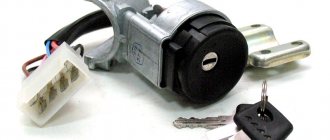
To start the car and set it in motion, the first thing we must do is place the key in the ignition, thereby starting the engine. Also, with the help of this device we can shut down the engine and control the electronics modes.
The ignition switch is the starting mechanism of electrical equipment that supplies voltage to the electrical circuit. The starter spins the engine using the flywheel, a large disc with teeth located between the clutch and the engine. During starting, the teeth of the starter and flywheel are brought into mesh position. At this time, the engine rotates according to a control signal from this lock using battery power.
During operation, the ignition switch supplies current from the battery to the starter traction relay. This is an important part, without which the machine will not fulfill its purpose. In addition to power control, the ignition switch prevents battery discharge in a quiet state. The engine starts from the starter by turning the key.
Types of the castle
Let's take a closer look at what ignition switches are. The following types of locks are found on the VAZ-2109 car:
- New sample. The lock has three positions and a short key.
- Old style. The lock has four positions, a long key and an ignition relay, the fourth position is for the parking light.
The key is removed in one position with the system turned off. In the first position the radio is turned on. In the second operating position, all electrical consumers are started. At the starting location, one starter is turned on, and the power supply to the system that consumes power is turned off. When the engine is running, the key returns to the second position. When at rest without a key in the lock, in the zero position, only lighting devices and alarms can continue to operate.
Thus, having studied the ignition switch diagram for the VAZ-2109, it should be noted that the lock consists of mechanics and electrics, where contact wires are located that supply current and thus start the car.
1200 rub. for the photo report
We pay for photo reports on car repairs. Earnings from 10,000 rubles/month.
Write:
The ignition switch, or ignition switch , is the main switching component that controls the flow of power to electrical systems and also prevents the battery from draining when the vehicle is parked and at rest.
Repair and replacement instructions
Basically, the protection zone can be repaired. Repair usually consists of replacing the core or contact group. If after repair the problem remains, then it is necessary.
On a VAZ 2109, replacing the core consists of the following steps:
- First, the protective and decorative cover is removed from the steering column, as well as the windshield washer and turn switches.
- The lock is secured with screws and a hook latch. There may be problems with unscrewing the screws, since their heads are cut off. To remove them, you first need to loosen them with chisels and then unscrew them with pliers. You can carefully drill out the screws.
- Next, we disconnect the clamps, disengaging them.
- By pulling out the side pin, you can remove the core. If that doesn’t work, the core can be drilled out using a thin drill. In extreme cases, you will have to dismantle the entire assembly.
- The next step is to disconnect the connector, wire plug, and ground wire.
- By releasing the latch, you can remove the cover and contact group.
- We insert a new core and check the work. When you turn the key, all processes should work.
The device provided for such an operation - the ignition switch - helps start most cars and drive further. It is equipped with both foreign-made cars and products of the domestic automobile industry, in particular, our “nines”. Breakdown or malfunction of this element will create difficulties for the driver to start the engine.
Having abandoned the left-hand drive position as in the “classics”, the designers took care of a comfortable right-hand place for using the key in their first front-wheel drive cars. This added ergonomics to the cabin. To perform its function, the main element used to start the car is equipped with two components:
- mechanical;
- electric.
The first block is responsible for fixing the steering wheel while the key is removed. The second block contains the pinout of the VAZ-2109 ignition switch, which is entrusted with the mission of supplying voltage to consumer electrical appliances.
The developers have provided for the presence of certain electrical devices in the ninth Lada model, which are capable of operating regardless of the state of the ignition unit. These include:
- car flashing emergency lights;
- “stops” of rear lights;
- dimensional optics;
- interior lighting;
- instrument panel light bulbs.
It must be taken into account that the VAZ-2109 ignition switch circuit is adjusted to its direct variety. Two types of locks can be installed in the “nines”:
- late model, which has three positions, does not use a relay and is activated with a short key;
- an early example that has four detent positions, a built-in relay and a long key.
Typically, drivers can easily visually determine the type of system installed. You can navigate by the working length of the key
The ignition switch consists of two parts:
- Mechanical - cylindrical lock (cylinder), it consists of a cylinder, into which the ignition key is inserted.
- Electrical - contact unit, consists of a group of contacts that closes using a certain algorithm when the key is turned.
The ignition key usually has a cylindrical lock, which copes with several tasks simultaneously, such as turning the contact assembly and locking the steering wheel. To lock, it uses a special locking rod, which, when you turn the key, moves out of the lock body and into a special groove in the steering column. The ignition switch itself has a simple design; now let’s try to disassemble all its components. For a more clear example, let’s look at how the ignition switch works:
Ignition switch parts
- a) type KZ813;
- b) type 2108-3704005-40;
- Brace.
- Frame.
- Contact part.
- Facing.
- Lock.
- A - hole for the fixing pin.
- B—fixing pin.
The cylinder is connected to a wire and installed inside a wide cylindrical spring, with one edge attached to the cylinder itself, and the other directly to the lock body. Using the spring, the lock can automatically return to its original position after turning on the ignition or after an unsuccessful attempt to start the power unit.
The lock driver can not only rotate the contact unit disk, but also fix the lock in the desired position. Especially for this purpose, the leash is made in the form of a wide cylinder, in which there is a radial channel passing through. There are balls on both sides of the channel, between them there is a spring, with the help of which the balls enter the holes from the inside of the lock body, thus ensuring their fixation.
The contact assembly has two main parts , such as: a contact disk that can be driven and a stationary block with visible contacts. There are plates installed on the disk itself; it is through them that current passes after turning the key in the ignition switch. Basically, up to 6 or more contacts are placed on the block; their outputs, as a rule, are located on the reverse side. Today, modern locks use contacts in the form of plates with a single connector.
Video “Replacing ZZ”
This video demonstrates the repair of the ignition switch of a VAZ 2109 (the author of the video is Vitaly Rau).
To check the ignition switch, sequentially set the key to the positions at which the circuits indicated in the table should be closed.
When the key is turned to position “III”, the anti-theft device should be activated. When turning the key from position “III” to position “0”, the anti-theft device should turn off. This can be checked by turning the steering wheel.
When restarting from position “I” to position “II”, the locking is activated. The key can only be turned to position “II” from position “0”.
If there are defects, replace the contact group or ignition switch for VAZ 2109, VAZ 21099, VAZ 2108, Lada Samara.
Key position
Live contacts
Switched circuits
Outdoor Lighting. Instrument lighting. High beam headlight alarm
Generator excitation winding. Ignition system. Windshield cleaner. Carburetor idle speed solenoid valve control unit. Direction indicators. Reversing light. Control devices
Low and high beam headlights. Fog light. Headlight cleaners. Rear window cleaner. Heated rear window. Washer. Heater fan. Engine cooling fan
1.
Unscrew the six screws securing the lower steering column casing of the VAZ 21099.
2.
Remove the lower steering column cover.
3.
. and lining of the ignition switch for VAZ 2108, VAZ 2109, VAZ 21099.
4.
Remove the upper steering column cover.
5.
Disconnect the ignition switch wiring harness from the wiring harness.
6.
Disconnect the block with the ignition switch wires from the ignition relay for the Lada Satellite.
7.
Insert the key into the ignition switch of the VAZ 2109 and turn it to position “0” to turn off the anti-theft device. Unscrew the four mounting bolts (two bolts are located on top of the column). Remove the bracket and ignition switch for the Lada Samara (see notes 1 and 2).
Note 1
If the bolt heads are sheared off, the bolts must be drilled out or removed using a screwdriver and hammer.
Note 2
Some cars are equipped with an ignition switch secured with two bolts. There is a slot at the top of the bracket that accepts the hook on the ignition switch housing.
8.
Unscrew the screw securing the switch cover.
9.
Remove the switch trim by pressing out the two plastic latches with a screwdriver.
10.
Remove the contact group.
11.
Assembling and installing the VAZ 2108 ignition switch is carried out in the reverse order.
Welcome! The ignition switch breaks quite rarely, but it still happens. After a lock breaks, it of course needs to be replaced with a new one, but how to do this, you ask? Some people still know the answer to this question, but some do not. For those who don’t know, we have prepared this article, which will describe in detail the process of replacing the ignition switch. And at the end of this article you will find a video clip that will describe in detail the process of replacing this lock.
Note! To replace the ignition switch, you will need the following tools: First, you will need screwdrivers, and you will also need a drill, a small hammer, pliers, and you will definitely need to stock up on a chisel!
Summary:
When do you need to change the ignition switch and contact group? It must be replaced if it breaks, as well as if the key is lost, and even if the cylinder in the lock stops turning and is stuck in one place. The contact group must be replaced if it is deformed, and even if, after turning the key in the lock, the car’s engine stops starting.
Note! Before you immediately say that the contact group of the lock is to blame for everything, first check the contacts of its wire blocks for functionality. (How to check the contacts of the contact group, see below in the section: “Checking the contacts of the wire block”)
Operating principle of the ignition switch
The lock's operating system is quite simple, so now let's look at the main tasks it can handle:
- The ability to connect and disconnect the vehicle’s electrical power system to the battery, in turn, after starting the engine, connect to the generator.
- Ability to connect and disconnect the engine ignition system to the power source.
- When the engine is started, the ignition switch may turn on the starter for a short period of time.
- Ensures the operation of such devices when the engine is off , such as: radio and alarm.
- Some ignition switch features can be used as an anti-theft feature , such as the ability to lock the steering wheel when the engine is at rest.
Ignition switches can have from two to four switch positions. Depending on the position of the ignition key in the car, you can determine which power systems are working at one time or another. The key in the car can only be pulled out in one position, when all power consumers are turned off. To have a more detailed understanding of the operation of the ignition switch, you need to familiarize yourself with its diagram:
Ignition switch operation diagram
In what positions can the ignition switch operate?
- "Turned off" . In cars of domestic manufacturers, this position is displayed as “0”, but on some older models the position had the value “I”. Today, in improved cars, this mark is not displayed on the lock at all.
- “On” or “Ignition” - on domestic cars the following designations are found: “I” and “II”, in newer versions it is “ON” or “3”.
- “Starter” - domestic cars “II” or “III”, in new cars – “START” or “4”.
- “Lock” or “Parking” - old cars are designated “III” or “IV”, foreign cars are marked “LOCK” or “0”.
- “Additional equipment” - domestic locks do not have this provision, foreign versions of the car are designated: “Ac” or “2”.
Ignition switch position diagram
When the key is inserted into the lock and turned clockwise, that is, it moves from the “Lock” to the “ON” position, then all the main electrical circuits of the car are turned on, such as: lighting, windshield wiper, heater and others. Foreign cars are designed a little differently; they have “Ass” immediately before the “ON” position, thus additionally starting the radio, cigarette lighter and interior lights. If you turn the key further clockwise, the lock will move to the “Starter” position, at this moment the relay should connect and the engine will start. This position cannot be locked because the key itself is held by the driver. After successfully starting the engine, the key returns to the initial position “Ignition” - “ON” and already in this state the key is fixed in one position until the engine stops completely. If it is necessary to turn off the engine, then in this case the key is simply turned to the “Off” position, then all power circuits are turned off and the engine stops.
Diagram of the key operation in the ignition switch
In cars with diesel engines, a valve is turned on to shut off the fuel supply and a flap that closes the air supply; as a result of all these actions, the electronic unit that controls the engine stops its operation. When the engine is completely stopped, the key can be switched to the “LOCK” position, after which the steering wheel becomes motionless. In foreign cars, in the “LOCK” position, all electrical circuits are turned off and the steering wheel is locked; cars with an automatic transmission additionally block the selector, which is in the “P” position.
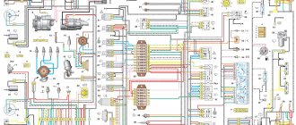
VAZ 2101 ignition switch wiring diagram
Power-up modes used
At each of the turns, the connection of certain devices is provided. There are markings in a circle in front of the socket indicating the position to which a certain mode corresponds.
Null
To activate this mode, just insert the key into the “secret”. In this case, devices that are directly connected to the battery remain active.
Additional consumers will be put into operation after the larva is rotated at a certain angle. Voltage is supplied to pins 30/1 and 30.
The first is “ignition”
In the first position, the driver can turn on the front lighting, such as the low and high headlights. The tidy and interior light up responsively. The connection diagram for the VAZ-2109 ignition switch is activated during this turn, releasing current to the 30–INT pair.
When there is a connection between terminals 30/1 and 15/1, the rear lights, reversing lights, turn signals are operational, and the generator excitation winding is energized. The XX solenoid valve also receives power.
In this position, contacts 30/1 and 15/2 are closed, which ensures the operation of, in addition to the head light optics, the functioning of the fog lights, the rear window wiper and its heating. The headlight cleaners, heater fan and engine cooling system propeller are connected to this contact.
The second is the “starter”
By moving the key to the current position, the driver does not block the connection of electrical consumers that were started in the previous “ignition” position. This fully applies to both the closed contacts of the pair 30/1 - 15/1, and to the pair 30 - INT.
The main change that the VAZ-2109 ignition switch connection diagram provides in such a situation is the activation of a pair of contacts 30–50. This allows the starter to start.
It is important to know that the key is not held in the “starter” position on its own, but springs back to the previous position automatically as soon as the driver releases the force.
Third – “parking”
At this angle of rotation, consumers started in the “ignition” position and closed contacts 30 – INT remain activated. A closed pair 30/1 - P is also added. It is responsible for the parking lighting.
How to properly connect the ignition switch
If the wires are collected into one chip, then connecting the lock will not be difficult, you just need to install it on the contacts.
If the wires are connected separately, then you need to pay attention to the diagram:
- terminal 50 – red wire, the starter operates with it;
- terminal 15 – blue with a black stripe, responsible for heating the interior, ignition and other devices;
- terminal 30 – pink wire;
- terminal 30/1 – brown wire;
- INT – black wire responsible for dimensions and headlights.
Wiring diagram
If the wiring has been connected, then everything needs to be assembled and the terminal connected to the battery and checked for functionality. First, you need to check whether all electrical appliances have power from the lock, then check the operation of the starter itself. If any malfunctions are detected , you need to once again check that the wires are connected correctly , because the operation of all devices in the car after turning the key will depend on this. Next, you can familiarize yourself with the ignition switch wiring diagram.
Connecting autorun
The VAZ-2114 models use an ignition switch with three terminals - 15 (blue wire), 30 (lilac) and 50 (red). Terminal 30 is connected to the battery. When you turn the key, blue wire 15 is connected to this terminal. The third terminal is responsible for the starter.
As it is written in the instructions, it is quite possible to power the alarm from contact 30, from which the lead is made. And the cable from connector X1, yellow, is connected to connector 15.
After all the actions taken, the connection of the tachometer remains. In this case, a loop antenna and a reading device are combined. Connector X3 has a gray-black outgoing wire. It is connected to the tachometer as shown in the VAZ dashboard diagram:
This will allow the alarm to control the speed. And at the very end we connect the ground from the main unit. This is a black cord from connector X3.
How does a contact group work?
The contact group in the car is designed to connect all the electrical circuits of the car and group them. When the driver turns the ignition key, the electrical circuit is closed from the minus terminal, which is located on the battery, to the ignition induction coil. Electric current from the wire system goes to the ignition switch, passes through the contacts on it, after which it is sent to the induction coil and returns to the “plus” terminal. The coil provides high voltage to the spark plug, through which current is supplied, then the key closes the contacts of the ignition circuit, after which the engine starts. After the contacts have closed with each other using the contact group, the key in the lock must be turned to several positions. After this, in position A, when the circuit from the power source distributes the voltage, all electrical appliances will start.
Settings
Only autorun functions can be configured. To activate programming mode:
- Disable security
- The ignition key is set to position 0.
- Then press the Valet key six times in the main block.
- Turn on the ignition
- After six beeps, use the same key to select the desired function, and use the key on the key fob to select the desired value.
The optimal settings for VAZ - 2115.2114 will be the following: function 12 - set to value 3, function 11 - value 4, function 9 - value 3. To select value 4, press and hold the third button until the melody is played. After playing, press it again.
To check the correct connections, perform the following steps:
- Disconnect the yellow cord from block A91 to terminal 15 for a while.
- The engine is started using the ignition key
At the same time, the alarm indicator should blink.
What can happen to the ignition switch
Most often, the ignition switch itself, the contact group or the locking mechanism can break down . Each breakdown has its own differences:
- If, when inserting the key into the cylinder, you notice some difficulties when entering , or the core does not turn well enough, then you should conclude that the lock has become faulty .
- If you cannot unlock the steering shaft in the first position, there is a breakdown in the locking mechanism .
- If there are no problems in the lock, but the ignition does not turn on , or, on the contrary, it turns on, but the starter does not work, then the fault must be looked for in the contact group .
- If the cylinder fails , then a complete replacement of the lock ; if the contact unit is broken, then it can be replaced without the cylinder. Although today it is much better and much cheaper to completely replace it than to repair the old ignition switch.
As a result of all the above, I would like to say that the ignition switch is one of the most reliable parts in a car, but it also tends to break. The most common breakdowns that can be encountered are jamming of the cylinder or its general wear, corrosion of the contacts, or mechanical damage to the contact unit. All these parts require careful care and timely diagnostics in order to avoid serious malfunctions. And if you didn’t manage to “outwit fate,” then in order to cope with its repair yourself, you must know the structure of the ignition switch and the principle of its operation.
Troubleshooting Methods
There are two methods for detecting faults:
- Visual;
- Diagnostic.
Ignition switch diagram
We suggest studying a visual method for determining a malfunction or breakdown of the contact elements of the ignition switch using the table.
| Action | The device is working properly | The device is faulty |
| Turn the key to the right position (ignition) | All electrical equipment turns on | All or part of the electrical equipment does not work |
| Turn the key to the second position | The starter is spinning | The starter does not work, the traction relay does not click under the hood |
But diagnostics allows you to get a more detailed answer. In addition, a visual inspection will not give you the opportunity to find all the reasons that could cause the ignition switch to break down.
To work, you will need a mini-tester and a multimeter in ohmmeter mode:
- Disconnect the power supply from the ignition switch. To do this, you need to remove the skin from the steering column;
- Switch your multimeter to an ohmmeter;
- On the block coming from the lock you need to find pins 7 and 4, which correspond to pins 15 and 30;
- Connect the multimeter probes to them;
- Turn the key to the “Ignition” position;
- On the block, find pins 7 and 3, corresponding to 50 and 30. Also connect a multimeter to them;
- Turn the key to the second position - Start the engine;
- If serviceability is present, the device will show zero resistance in both test cases.
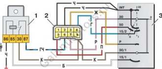
Wiring diagram for the ignition switch on the VAZ-2108, 2109 and 21099
Wiring diagram for the ignition switch on the old-style VAZ-2108, 2109 and 21099 with an unloading relay.
Pinout of the VAZ-2109 ignition switch with unloading relay:
- comes +12V in position I, II, III (parking)
- comes +12V in position I, II, III (parking)
- comes +12V in position III (parking)
- position I, +12V goes out after turning on the ignition (contact 15/2), disappears at start (II);
- position I, +12V goes to the starter (pin 50);
- position I, +12V goes away after turning on the ignition (pin 15), does not disappear when starting II;
- +12V comes from the battery (pin 30);
- comes +12V constantly.
Wiring diagram for the ignition switch on the VAZ-2108, 2109 and 21099 of the new model, without a relay.
Pinout of the new VAZ-2109 ignition switch:
- comes +12V constantly
- comes +12V constantly
- +12V arrives after turning on the ignition (pin 15), does not disappear when starting II;
- +12V arrives after turning on the ignition (contact 15/2), disappears at start (II);
- position I, +12V goes to the starter (pin 50);
- +12V arrives after turning on the ignition (pin 15), does not disappear when starting II;
- +12V comes from the battery (pin 30);
- comes +12V constantly.
Photo 1, pinout of the new VAZ 2109 ignition switch
Photo 2, pinout of the new VAZ 2109 ignition switch
Preparation
It is necessary to prepare spare parts and other equipment for work. A new ignition switch will be needed. It is quite easy to find original parts and analogues on the Internet, but it is worth considering that it is advisable to purchase the lock “assembled”.
Catalog number of the original VAZ 2114 ignition switch: 21103704010. Approximate price: 500 rubles for a used part and 1200 for a new one.
As a replacement, you can use analogues with numbers: 09401, 24370407. Approximate price: 1000 rubles (new part).
In addition to the lock itself, you will need the following tools:
- spanners;
- chisel;
- pliers;
- screwdriver.
Before you begin, you must also remove the steering column cover and steering column switches.
Ignition switch VAZ 2109 faults
The ignition switch of the VAZ 2109 is a very important and at the same time very capricious mechanism of the car. And in today’s article we will try to analyze its importance and capriciousness, i.e. its malfunctions. The ignition switch serves to supply voltage to electrical circuits depending on the location of the key. The castle consists of 2 parts. These are the mechanical and electrical parts.
As has already been written, in our nine the ignition switch is a very important mechanism. Almost all of the car's electrics pass through it. Without an ignition switch, only a few devices can operate and these are:
1. Side lights.
2. Emergency alarm.
3. Interior lighting.
5. Rear number plate illumination.
This is necessary so that when stopping on the highway or in the city in an unlit place, we do not need to turn on the ignition in order to be noticed.
Malfunctions
Considering that the ignition switch is designed to perform two functions, all breakdowns are divided into mechanical and electrical. Mechanical malfunctions include jamming of the cylinder in one of the positions when it is impossible to turn the key. Contact group, which is time to change when the car engine does not start when you turn the key or deformation has occurred.
In a situation where there is no contact, all components of the system do not function. If there is a contact in the wrong place, a short circuit and overheating will occur, which will lead to the need to install a new lock.
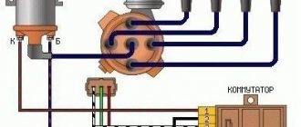
VAZ 2109 ignition switch diagram.
The ignition locks for the VAZ 2109 can be of different designs. There are 2 samples, this. new and old. The new one differs from the old one only in the absence of a relay, a shortened key and three key positions instead of four.
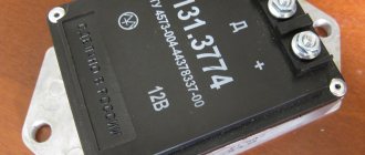
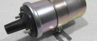
1. Ignition relay
2. Ignition switch connector
3. Ignition switch.
Name of modes, position of the lock and power circuit.
| Key position in the lock | Live pin numbers | Circuits that are included |
| 0 - disabled | 30 and 30/1 | The car is de-energized, power is provided only in circuits connected directly to the battery |
| "I" - ignition | 30 - INT | At the current position of the key, the external lighting, high and low beam headlights, instrument lighting and lighting in the car interior work. |
| 30/1 — 15/1 | All control devices, reversing light, windshield wiper, generator excitation winding, direction indicators, idle speed solenoid valve control unit must work. | |
| 30/1 — 15/2 | In this position, the low and high beam headlights, rear front fog lights, rear window cleaner and heating, washer, heater fan, engine cooling system fan, and headlight cleaners operate. | |
| "II" - starter | 30 - INT | The same circuits operate as in the ignition position. |
| 30/1 — 15/1 | The same circuits operate as in the ignition position. | |
| 30 — 50 | The starter turns on | |
| "III" - parking | 30 - INT | The same circuits operate as in the ignition position. |
| 30/1 - R | Parking lighting |
The ignition switch of the VAZ 2109 is faulty.
The most common problem with the ignition lock is its working out and jamming. If these symptoms occur, you should immediately replace the entire ignition switch, because in case of jamming, you can simply burn the starter and then the repair will cost you the cost of the starter. Another common problem is the failure of the contact group. In this case, several devices fail at once. For example, my low beam headlights, heater, cigarette lighter, and rear window heater immediately stopped working. Replacing the contact group with a new one, everything worked immediately.
© 2022 Repair and tuning of domestic cars Joomla! is Free Software released under the GNU General Public License.
Symptoms of a problem
What are the symptoms of a failed ignition switch? Let's start with the fact that its malfunction can be either mechanical or electrical in nature. In the first case it is:
- lock jamming in one of the positions;
- inability to unlock the steering shaft;
- turning on the ignition with a non-original key or other object.
If the lock has an electrical problem, you may notice the following symptoms:
- the warning lights on the instrument panel do not light up or light up and go out periodically;
- the starter does not start;
- Some or all electrical appliances, the circuit of which is powered through the ignition switch, do not work (cigarette lighter, headlights, washer, wipers, etc.).
Design and troubleshooting of the ignition switch of the VAZ 2109
One of the key components on a VAZ 2109 vehicle is the ignition switch. The electrical circuit of the machine uses it as a switching unit, providing voltage to the necessary power circuits. If this does not happen due to a malfunction of the switch, then it is possible to turn off individual groups of consumers or the car as a whole - it simply will not start.
Design and principle of operation of the lock assembly
On a VAZ 2109 car, 2 standard modifications of the lock can be installed. The old one has catalog number 21080-3704005-60. It features four key positions (long), and also contains an ignition relay. The new unit with catalog number 21080-3704005-30 has only three key positions and does not have a relay.
To connect all the wires to the VAZ 2109 car lock, a contact group is used. Each of the key positions has its own blocking, and therefore consumer groups.
Contacts “30” and “30/1” are closed. All dependent power circuits are disabled.
In this position, voltage is supplied to the elements of the ignition control system. To do this, the white and brown wires are connected, and the pink wire is connected to black and blue. In this case, several groups of contacts are formed. For example, “30 INT” turns on the power supply circuit for external lighting, including high beam lighting, and the dashboard lighting. Contacts “30/1” and “15/1” provide voltage to the direction indicator lamps, reverse lights, elements of the ignition system, etc. The pair “30/1”, “15/2” powers the low/high beam headlights, fog lights , washer, fans.
The ignition relay, which was switched on in the previous step, continues to operate. The main one is a pair of contacts “30”, “50”, which provides voltage for the starter to operate. In parallel to it, circuits should be formed from contact connections “30/1”, “15/1”, as well as “30/1”, “15/2”. The consumers that are connected in this case are similar to those described for position “I”. The pink wire in the contact pair, together with the black one, is shorted to red (instead of blue).
Used to supply voltage to the components of the parking (“30/1 P”) and side lighting/dashboard lighting (“30 INT”) components. The black wire forms a closed circuit with the brown and pink wires.
The lock and its circuit perform two functions: electrical and mechanical. The essence of the first is to close certain groups of contacts based on the position of the key. From a mechanical point of view, when the ignition is turned off, the steering wheel is blocked, making it impossible to rotate. That is, the second function is protective.
Testing the serviceability
The lock's service life is limited. After it fails, it is necessary to repair or completely replace the product. The functionality is checked after inserting the key into the “secret”.
Failures occur due to mechanical wear or loss of contact. The check is carried out by turning the key. If it begins to jam, then as a temporary solution it is possible to use silicone grease by dripping it inside.
In order for the wiring diagram to function correctly, you need to know which contacts to connect to each other. Typically the following wiring system is used:
- red connects to the cable from the starter;
- the pink wire goes to “+” from the 12 V battery;
- brown +12 V is used to start the ignition relay;
- white – relay on;
- black and blue connect other consumers.
It is necessary to check the contacts for the presence of carbon deposits or the possibility of oxidation. Burning contacts can be heard in the cabin by the characteristic smell of burnt insulation.
Voltage is supplied to the electrical power circuits of consumers of electrical equipment of VAZ 2108, 21081, 21083, 2109, 21091, 21093, 21099 vehicles through the ignition switch (lock).
For current unloading of the ignition switch contacts, an ignition relay 113.4737-10 is included in its circuit, which is mounted next to it under the instrument panel.
Ignition switch wires for VAZ 2108, 21081, 21083, 2109, 21091, 21093, 21099 cars, connection order, pinout
Ignition key position: “O” (off)
The lock contacts “30” (pink wire – “plus” from the generator) and “30/1” (brown wire – “plus” from the generator) are energized. No electric current flows into the system.
Key position: “I” (ignition)
Contacts “30” (pink wire) and INT (black wire) are closed. Voltage is supplied through one black wire to the exterior lighting switch, instrument lighting switch, through the other to the steering column switch for briefly turning on the high beam headlights.
Contacts “30/1” (brown “positive” wire) and 15/2 (blue wire) are closed. Voltage is supplied to the generator excitation winding, the ignition system, to the windshield wiper, carburetor solenoid valve control unit, turn indicators, reversing lamps, and control devices.
Contacts “30” (pink “positive” wire) and “15/2” (blue wire) are closed. The low and high beam headlights, fog lights, headlight cleaners, rear window cleaner, heated rear window, washer, heater fan, and engine cooling fan on the radiator are turned on.
Key position “II” (starter)
Contacts “30” (pink wire) and “50” (red wire to the starter) are closed.
In addition, “30” and “INT” remain closed, as well as 30/1 (brown wire) and “15/1” (white wire on the ignition relay).
Key position “III” (parking)
“30” and “INT”, “30/1” and “P” are closed (on VAZ 2108, 2109, 21099 cars this contact was used to turn on the parking light, the wire is yellow).
Notes and additions
— They are not powered through the ignition switch: emergency, sound, light alarms, interior lighting, dimensions, brake lights. security alarm. electric door locks (if equipped).
More articles on electrical equipment of VAZ 2108, 2109, 21099 cars
Malfunctions of the ignition switch of the VAZ 2109 are quite common. This element consists of two parts: mechanical and electrical. Because of this, malfunctions of the ignition switch on the VAZ 2109 can pose a big problem for many, which they cannot cope with on their own. This publication aims to familiarize the reader with all known malfunctions of the ignition switch and explain how to fix them.