Signs of a faulty switch: how to check the switch yourself.
Purpose and design features of the switch.
A switch is one of the elements of a car's electrical equipment. His task
– ensuring normal operation of the contactless ignition system. The assembly is fastened in the engine compartment.
The device is different
reliability, ability to withstand severe vibrations and shock loads. This is very important, because the switch housing contains sensitive electronics.
At the heart of the VAZ switch
– standard L 497 microcircuit, which controls an “NPN” type transistor.
>Scheme feature
– possibility of programming by the user and setting the required delay coefficient. Starting a cold engine directly depends on the correctness of this indicator.
Thanks to precise settings
, you can speed up the crankshaft rotation speed (while eliminating failures in operation) and guarantee high-quality traction of the power unit.
The main parameters of the switch device include:
Voltage range – from 6 to 16 Volts; operating voltage level – 13.5 Volts; ensuring an uninterrupted spark when the crankshaft rotates in the range from 20 to 7000 rpm; switching current – from 7.5 to 8.5 A.
Signs of a faulty switch.
One of the main symptoms of a faulty switch is loss of spark.
. The engine starts hard and stalls from time to time, causing interruptions in operation.
But don't rush to replace it
- it is important to verify the reason, because
loss of spark can occur for a number of reasons
- failure of the Hall sensor, rupture of the timing belt, malfunction of the ignition coil, poor contact in the distributor cap, problems in the wiring, and so on.
Therefore, first of all, a comprehensive diagnosis is necessary. The fastest and most effective way in this case can be a car diagnostic scanner. For the most part, this type of device is quite easy to use and has an affordable price. Of those presented on our market, we can recommend paying attention to the multi-brand scanner Scan Tool Pro Black Edition.
The advantages of this model include diagnostics of not only the engine, but also other components. Compatible with 99% of new and old cars since 1993, quite easy to use and has wide functionality.
If diagnostics of other nodes does not produce results
, then we can move on to our “hero”. But how to check the switch, since the device has a very complex design?
How to check the switch yourself.
Most car enthusiasts don’t bother with diagnostics and simply install a new unit. This method has its advantages.
Firstly
, there is no need to waste time checking - just install a new part.
Secondly
, you can immediately determine whether this is the reason or not. In fact, there is no need to be afraid of the work, because checking the switch takes a few minutes.
So, to carry out work at home, a test lamp (nominal voltage should be 12 Volts) and a standard set of keys are enough.
With their help, you can verify the presence or absence of pulses, and later make a decision about the serviceability of the device itself.
Algorithm for checking the switch:
To begin work, it is advisable to disconnect the battery so as not to accidentally short-circuit the wiring that you will unscrew.
Using an eight-point wrench, unscrew the nut and remove the wiring from the ignition coil marked “K”. This wire is easy to recognize - it is brownish in color and goes to the terminal labeled one on the switch;
Connect this wire through a control light to terminal “K” on the ignition coil, and then connect the battery;
Turn on the engine starter and observe the lamp's actions. If it blinks, then the switch is working. If the light bulb does not show any signs of life, then the only way out is to replace the device.
If there are doubts about the serviceability of a part, the check should be carried out on a special stand (there is always one at the service station).
In this case, it is possible not only to determine whether the product is working, but also to measure the duration of the pulses.
When the first suspicions appear, you should not immediately change the switch or spend money on a specialist. You are quite capable of doing the job yourself.
Moreover, now you know how to check the switch on the VAZ 2109 and other models of the domestic brand. All that remains is to allocate time and prepare a minimum set of tools. Have a good trip and of course no breakdowns.
Sometimes when diagnosing a carburetor gasoline engine of a passenger car, difficulties arise in determining the cause of a particular malfunction. This happens because the symptoms of their manifestation are very similar. For example, carburetor malfunctions and ignition system malfunctions will have almost the same effect on engine performance. In this article we will try to understand what problems in the operation of a car engine arise due to a malfunction of the ignition system.
Car engine does not start
— Battery is faulty
— The switch is faulty
— Hall sensor is faulty
— The insulation of high-voltage wires is “broken”
— The distributor cover is “broken” or is heavily oxidized, its contacts are destroyed
— Ignition distributor rotor (slider) burnt out
— The ignition coil is faulty or its cover is “broken”
— High-voltage wires are connected in the wrong order
— Defective spark plugs, their insulation is “broken,” the gap between their electrodes does not correspond to the norm
— Incorrect ignition timing
Ignition is either too early or too late. How to correctly set the ignition timing on VAZ 2108, 21081, 21083 engines is described in detail on the page “Setting the ignition timing of VAZ 2108, 2109, 21099 cars.”
— The low voltage circuit of the ignition system is faulty (contacts have oxidized, wires are broken, connectors have come off...)
Read more about the inability to start the carburetor engine of VAZ 2108, 2109, 21099 cars in the article “The carburetor engine does not start (reasons related to the ignition system).”
For comparison, you can see what reasons exist that the engine cannot be started due to a carburetor malfunction.
The car engine runs erratically (troits) or stalls at idle
— The gap between the electrodes of the spark plugs does not correspond to the norm
— Heavy carbon deposits on the spark plug electrodes
— Defective spark plugs (“insulator broken”)
— Incorrect ignition timing
— The switch is faulty
— The centrifugal ignition timing regulator in the distributor is faulty (weights stick, their springs are weakened or broken, damper rings are lost)
Causes of rough idle related to the carburetor are outlined on the “Rough Idling” page.
Dips and jerks in engine operation
— Incorrect ignition timing
— The gaps between the electrodes of the spark plugs do not correspond to the norm
— Defective spark plugs
— The noise suppression resistor in the rotor (runner) of the distributor burned out
— Wear or damage to the contact carbon in the distributor cover
— Current leakage through “broken” insulation of high-voltage wires, spark plug insulator, ignition coil cover
For the causes of malfunction related to the carburetor, see the page “Failure when pressing the gas pedal.”
The engine does not develop full power, its throttle response is reduced
All of the above causes of malfunctions lead to loss of power, throttle response of the car engine, and increased fuel appetite. You can only add
— Malfunction of the vacuum ignition timing regulator in the distributor due to jamming of its plate
Notes and additions
Five more articles on the site on the ignition system of VAZ cars
A power supply and a pair of wires are all that constitutes a car ignition switch. But on the other hand, this is a rather complex and responsible unit. Today it continues to evolve, showing better and better combustion ratios. At the same time, advanced devices are able to work effectively on the AI-93, increasing the engine output at low speeds.
The switch is the basis for uninterrupted engine operation
The VAZ 2109 car is equipped with a contactless ignition system.
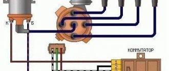
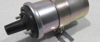
The system includes spark plugs, four high-voltage wires (one for each spark plug), a Hall sensor, a distributor, an ignition coil and, in fact, a switch.
Rice. 1 Ignition circuit of VAZ 2109 Schematic illustration.
The ignition system generates an electrical impulse (spark), thereby igniting the mixture of fuel and air in the combustion chambers necessary for engine operation.
The switch is responsible for the cyclic supply of pulses to the ignition coil, this is necessary for the proper operation of the entire system as a whole.
Thus, if the switch is faulty, the spark will supply intermittently or be completely absent. It is not possible to drive such a car.
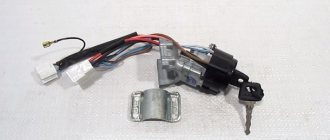
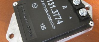
The VAZ 2109 switch itself consists of an aluminum case and a microcircuit installed on it. The device is mounted in the engine compartment and connected by wires to the ignition coil.
Rice. 2 Appearance of the VAZ 2109 switch.
The design of the housing and the mounting method allow the switch to successfully withstand vibrations that occur when the car is moving.
The VAZ 2109 contactless ignition system switch has the following performance characteristics:
- Voltage range 6–16 Volts.
- Operating voltage 13.5 Volts.
- Switching current 7.5–8.5 Amperes.
- A switch in good condition ensures an uninterrupted supply of spark to the cylinders with a crankshaft speed of up to 7000 rpm.
What is it for, where is it located and what does it look like?
As was said, the switch is needed for driving on low-octane gasoline. This fuel costs much less than premium grades. At the same time, the engine output still remains at a high level due to better ignition of the air-fuel mixture. Thus, the switch is a device that promotes the appearance of a productive spark in the ignition unit. It can be considered a microcomputer stimulating the converter. Naturally, the switch must rely on some data. In our case, these are signals from the synchronization sensor.
On cars with LPG, the switch performs one more task: it tests the ignition components, adjusting the OZ with the autopilot during switching to methane.
Structurally, the element can be combined with the ECU. In this case, it is located on the distributor (VAZ 2106, 2107) or next to the converter - on the ZIL TK102U. The option of being on a separate metal platform is no exception. As a rule, this is either a car fender or a partition under the hood (Ford). And on German Audis the switch is installed in the engine compartment under the windshield. It is provided with a protective casing made of moisture-proof material.
Design and principle of operation
The first switches were extremely primitive. A simple circuit of transistors was regulated using an electrical impulse. The device did not last long in this form. The era of high technology has arrived, thanks to which more effective innovative solutions have begun to be applied.
On cars assembled in the Russian Federation, the spark stimulator was first used on the VAZ-2108 car. The device belonged to the 36.3734 series, also of native production. Subsequently, more modernized switches with different design and technical designs began to be used. However, combined or composite assembly technology has always remained unchanged for Russian microcircuits. And its advantage is that it is repairable, unlike the same foreign analogues.
Today, a switch is a combination of several elements: spark plugs, transistors, sensors. It can be used in hybrid or thyristor ignition. Electrical impulses are controlled automatically, which provides a number of practical advantages:
- no interruptions at maximum speeds;
- increasing the reliability of the unit;
- possibility of increasing the engine cylinder capacity.
And when the Hall element was introduced, and the switch began to control several converters at once, the advantages only increased. So much so that they began to use a “coil + commutator” tandem on each individual spark plug. Here's what exactly we managed to achieve:
- the spark in the ignition system has become stronger and more reliable;
- power losses in the distributor have disappeared;
- improved idle speed;
- fuel consumption has decreased;
- Starting on a cold engine has stabilized.
The principle of operation of the switch can be imagined as follows. First, the system monitors the position of the engine crankshaft. Then, an inductive Hall sensor included in the distributor design takes readings from the position of the pistons in the cylinders. It also supplies the switch with an impulse. The signal is amplified to 12 volts and sent to a coil. Due to this, the current decreases and the voltage increases.
Nowadays, electronic switches are used for efficient ignition of fuel in VAZ 2109, 2110, 2114 Samara, as well as ZAZ-1102. The 3734 series of these devices is produced under article numbers 3620-, 36- and 78. The tasks of the key here are performed by a productive mosfit, and the current value is controlled by an integrated electrical circuit.
Connection diagram
It turns out that the role of commutation is simply to amplify the pulse to the required value. This is true, because it is not without reason that designers compare the described element with Darlington field-effect transistors. Only in the switch the main function is performed by an inductive sensor with three terminals. When a metal plate enters the sensor area, current generation begins. Next, the voltage is applied to the input of the switch. Here the pulse only increases and goes further to the converter.
The ignition switch circuit is quite simple. It's difficult to install. It must be carried out as competently as possible, otherwise there will be no point. An important nuance also concerns the selection of transistors. They must be checked through special measuring equipment, since even seemingly identical semiconductors have very different characteristics.
Below, as an example, is a diagram of a 4-port switch 76.3734 type KET, used on VAZ cars:
- intended for BSZ;
- consists of controller L497 or its analog KR1055ХП2;
- connection to a tachometer located on the dashboard is possible;
- classic connection - through a two-stage amplifier unit.
Now according to his conclusions:
- 1 (output), an amplified pulse is removed from it - connected to the main terminal of the coil;
- 2 (contact) - connects to the negative terminal of the battery;
- 3 (ground) - integrated internally by a block with contact 2;
- 4 - receives power from the battery;
- 5 - outputs constant power, always 12 V.
It is noteworthy that a voltage stabilizer is used between 4 and 5, since there is always resistance here.
A more detailed diagram of connecting the switch to the VAZ 2108 is shown in the photo.
Existing types of switches
There are two main types of devices: AC CDI and DC CDI. The first switches were small and simple, using a high-voltage generator in their circuitry. The latter are more common, equipped with four contact groups with minus and plus, as well as separate outputs for the coil and Hall sensor. But the latter function only in the presence of high voltage supplied from an external source.
Switches are also usually classified according to their functional features:
- traditional or stock devices that strictly correspond to the parameters of the car - as a rule, they are installed from the factory;
- sports - they have the ability to increase the upper limit of the number of revolutions of the internal combustion engine, however, this type is the lot of experienced specialists and has the risk of accidents;
- with the ability to adjust the phases of the UZ - an excellent option when you need to equalize the torque of the power plant, improve acceleration characteristics and stabilize engine operation at different speeds.
Of course, switches are usually divided into main types.
Electronic
This type of switch is also called a microprocessor switch with transit keys. It is used to control the converter voltage and reduces the load on the connections, thereby increasing the current capacity.
Advantages of the electronic system:
- possibility of better filling of internal combustion engine cylinders;
- efficient engine output at all speeds.
Hybrid
These systems additionally use a mechanical part - a cam distributor. The electronics are represented by the switch itself and the coil. The unit is very reliable, economical and convenient. For example, if a switch fails, you can switch to an old converter with a slider.
Contactless
A group with transistors, widely used since the early eighties. It replaced the antediluvian classical contact systems. At one time it was considered the most effective, since its performance indicators were much higher than those of other switches.
Dual channel
The same contactless system, but significantly modernized. For example, a conventional BSZ has the same disadvantages of a KSZ - loss of spark energy, instability of idle speed, limitation on adjustment of the SPD, high sensitivity to pollution and humidity. A two-channel system or DBSZ eliminates these disadvantages from the ignition system, providing even higher spark energy through the use of additional coils. Also, problematic moving elements - a slider and a coal - are not used here, and the lid serves only as a protective element. Therefore, it is not subject to burnout.
Interestingly, two-channel ignition was used before. This was implemented on export VAZ-21083. However, switches of this type, also called dual-circuit switches, were not widely used due to the poor quality of the electronics of that time.
One more nuance regarding switches. They may have different outputs. Those with the default number “1” are extremely dangerous for the ignition coils at the moment they experience malfunctions. But the advantage of such devices is that standard converters for contact ignition can be integrated with them.
For the second types of switches, in which output “0” is used by default, conventional coils are completely unsuitable. They will get very hot, or the spark will not flow properly. Such a switch includes, for example, the model for BTsZ 131.3734.
How to repair a distributor on a VAZ 2101-VAZ 2107?
Note! We will outline the repair process on a contact ignition distributor, but we will not touch the non-contact distributor (We will also call it a distributor, because it is the same thing), since, firstly, it spends quite a long time, and secondly, if something goes wrong with it, then it’s either the hall sensor is stuck, or the distributor cap is broken, or the rotor is also called a slider that breaks through, well, the vacuum regulator, in fact, there’s nothing else to break there, but in a contact distributor, the contacts themselves constantly oxidize (Especially if your car is parked all the time on the street, or in an unheated garage in which the humidity is very high), because of this you have to disassemble it and clean them (Contacts can be cleaned with an ordinary school eraser, some Also, sandpaper, which is also called sandpaper, is used to clean contacts, but we don’t recommend it for you because it spoils them and leaves dirt, well, you can also use a needle file, and by the way, it’s best for them)!
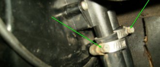
Disassembly: 1) First, remove the unit itself from the car and do not forget to prepare the place where you will work, there should not be any kind of dirt and especially water in the vicinity, if it gets on the contacts it will simply render them unusable and then make them more careful You can see the process of removing the distributor in the article entitled: “Replacing the ignition distributor on a car.”
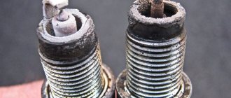
2) Now that the distributor has been removed, disconnect the top cover from it; to do this, pick up the two side clamps that secure it (the easiest way is to pry them off with a screwdriver; they don’t always come off by hand), after it is disconnected, look at the contacts (There are only four of them , for clarity, some are indicated by arrows in a small photo) there should be no oxidation on them and they should be of a catchy color, and by the way, also check the central rod, press it several times; under no circumstances should it be broken and should walk smoothly without any damage or jamming, it is indicated by a blue arrow in a small photo.
Note! In addition, there shouldn’t be any cracks on the cover itself and it should be intact, in other words, not have any hollows or dents, besides, for clarity, a cover from a completely different car is shown below, but that’s not the point, look at its contacts , these contacts are oxidized so that you can already understand how it looks, you can clean them with a needle file until they shine (10-15 minutes of work) and it will start working for you again, or you can simply change it to a new one if the contacts are no longer cleaned!
Symptoms of a Switch Problem
Loss of spark by the ignition system is one of the main symptoms of a lack of serviceability of the switch. Naturally, this is accompanied by difficulty starting the engine and interruptions in its operation. However, experts warn that there is no need to rush to replace the element, because similar symptoms are also present in other problems. For example, this also happens when the timing belt breaks, the distributor or ignition coil is damaged, the wiring connections are weak, etc.
In a word, you need to check the switch correctly. But how can you do this without qualifications, because the device has a complex design. There are several practical ways. The first is not to bother and install a new switch. If the problem goes away, then everything is fine. The second method involves using a 12-volt test lamp and a standard set of keys.
Following are the instructions:
- de-energize the battery;
- remove the control wire “K” from the ignition coil - it is often painted brown or red and routed to the main terminal of the switch;
- In its place, install one end of the control lamp, connect the other to wire “K”;
- connect external power supply 12 volts - battery;
- start the engine.
If the lamp starts blinking, the switch is working. The opposite situation, when the indicator does not show any operating signs, will indicate problems with the device. It is unlikely that it has completely deteriorated, then the engine would not start the first time.
Signs of a switch malfunction can be more accurately seen on professional equipment - a special stand. This makes it possible not only to determine whether the device is working, but also to calculate the duration of the pulses. In addition, specialists separately measure the voltage at the output of the Hall sensor - the norm is no more than 0.4 V. The first and second terminals of the switch are also closed when the ignition is on to test for the presence of a spark.
Alternative diagnostic methods
When there is no voltmeter on the dashboard, you can get out of the situation by doing everything yourself. To do this, you will need a 12 V light bulb and two meter wires with stripped ends. The diagnostic work flow diagram is as follows:
- disconnect the battery, de-energize the electrical system;
- using a size 8 wrench, unscrew the nut and remove the wire from the ignition coil terminal marked “K”, this wire is brown and goes to the clamp marked “1” on the switch;
- connect this wire to one of the test lamp wires;
- Connect the other wire of the control lamp to terminal “K” on the ignition coil;
- connect the battery;
- Turn on the engine starter and observe the condition of the lamp. If the lamp is flashing, the device is working properly. If the lamp does not light, the device is faulty.
Repair and replacement instructions
It is worth noting that modern Russian switches are suitable for output key transistors not only of standard production, and in particular KT890A, KT898A1, but also the foreign analogue BU931. It can be implemented either without a housing or in the TO-220 or TO-3 design.
As for the control circuit, the 78.3734 series switches are suitable for:
- 4-channel amplifier type K1401UD2B;
- domestic microcircuit R1055ХП1;
- foreign L497B SGS-TOMSON.
Before replacing the switch or its components, it is recommended to test the integrity of the wiring and connections of the ignition system. Pay special attention to the generator. It is also a good idea to check the voltage from the on-board network to the Hall sensor.
More details on faults and how to repair them are given in the table below.
Price
More details in the table.
And finally, remember that when replacing a powerful switching transistor, it is important to pay attention to the quality of fixation of the part to the switch body. Many beginners make mistakes here or do not apply enough heat-conducting paste. As a result, the device cannot be repaired.
A characteristic feature of the car can be considered its rapid obsolescence, but long life. The most modern car today, in at least two years, will be inferior to other, newer cars with improved characteristics. But even now there are cars from the last century on the roads. Therefore, it is not just interesting, but sometimes necessary, to know at least in general terms what such vehicles are, their structure, features, including such a thing as a simple ignition switch, which significantly changed the capabilities of the car.
Contactless systems and Hall sensor in the distributor
The distributor described above is a classic version and was used for many years on all cars, including the VAZ family, such as 2109, 2106, 2107, 2108. However, as electronics developed, voltage switches began to appear in which the breaker signal was used not for switching the ignition coil, but for controlling the electronics. Later, the distributor lost its mechanical breaker and was replaced by a Hall sensor.
The Hall sensor used has a fairly simple design. Yes, it must be recalled that the Hall sensor is an element that responds to a magnetic field. Therefore, the design of the sensor using Hall elements is based on this principle. To do this, a Hall sensor is located directly on the plate, on the other side there is a permanent magnet, and between them there is a rotating metal screen in which special slots are made.
When the screen blocks the field from the installed magnet, the Hall sensor has zero voltage at the output; when windows are opened instead of a solid screen, the Hall sensor generates a high voltage at the output. The distributor transmits this generated sequence of pulses to the voltage switch, and it controls the ignition coil.
At one time, a similar system was implemented in many cars, VAZ 2109, 2106, 2107, 2108 were no exception.
What is and what is the principle of operation of the ignition switch
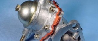
Even on the very first cars, battery ignition systems were used to ignite the combustible mixture, the functional diagram of which is shown in the figure.
This figure allows you to understand that its work is based on the principle of self-induction. When the current flow circuit in the winding of bobbin 3 is broken, a high-voltage EMF is induced in the secondary, causing a spark to appear on the contacts of spark plug 2. The circuit break is caused by the opening of the contacts of breaker 6.
Without touching on the advantages or disadvantages, it should be noted that this scheme worked on the car for a long time. And only the emergence of a new element base gave impetus to the further development of such a device, preserving the original principle of its operation.
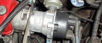
Why do you need a distributor?
The ignition system is a critical part of a gasoline engine. The operation of the latter is based on the timely combustion of the fuel-air mixture (FA), for which purpose a high-voltage voltage is specially generated, which is then supplied to the spark plugs. A spark is formed on them, causing combustion of the fuel assemblies, as a result of which the engine performs useful work. This is roughly how you can briefly describe the operating principle of a gasoline internal combustion engine.
All these processes require a distributor. If we evaluate its role during the operation of the ignition, it should be noted that it:
- initiates the onset of sparking due to the opening of the breaker contacts (in more modern car models, for example, VAZ 2109, 2106, 2107, 2108 of the last years of production, a Hall sensor is used for these purposes);
- directs the high voltage generated in the ignition coil to the desired spark plug;
- changes the beginning of the moment of spark formation depending on the driving modes and the fuel used, for which vacuum centrifugal regulators are used;
- provides accumulation and discharge of energy in the reel.
A functional ignition diagram will allow you to better understand what the distributor is used for and how it works:
What could the ignition system switch look like?
The above switch circuit is just one of the options for how the ignition device can be implemented. This is done using:
- transistors;
- thyristors:
- hybrid elements;
- contactless sensors.
The transistor circuit of the switch is discussed above; the thyristor circuit uses energy accumulation in the capacitor, and not in the electromagnetic field of the ignition coil. During operation of the thyristor system, when control signals are received, the circuit connects a charged capacitor to the windings of the coil, through which it is discharged, causing a spark to appear. Without touching on the advantages and disadvantages that this or that circuit has, suffice it to say that any such device provides a significant improvement in all parameters of the ignition system, and the switch over time has replaced conventional battery ignition.
However, it is necessary to note one more stage in the development of the system, and the switch in particular. The use of electronic components and the introduction of a switch into the design of the car made it possible over time to abandon the contact voltage breaker and replace it with a contactless sensor. Such a system, in domestic cars, was first used in VAZ cars, in particular the VAZ 2108. A similar operating principle, when the switch receives signals from a special unit, is implemented on the VAZ 2108 using a Hall sensor.
When considering the options for what the switch device could be, one cannot ignore the development of the ignition system itself. The main principle that is implemented during its construction is to increase the reliability and efficiency of the entire system. This is achieved by using microprocessor systems that use the readings of numerous sensors. To work with such systems, you need at least a two-channel switch, and recently a separate coil and switch for each spark plug. This approach – a two-channel switch (later also multi-channel) allows you to provide:
- more powerful spark;
- elimination of losses in the distributor;
- stable idle;
- improved starting at low temperatures;
- reduction in fuel consumption.
It is worth noting that a two-channel switch allows you to get rid of the slider.
What does the distributor consist of?
A device such as a distributor includes a large number of different parts. It is not the purpose of this material to consider their purpose, but you can see what components the distributor consists of in the figure below
As can be seen from the figure, the distributor consists of several independent units. And if the purpose and operating principle of the voltage distributor unit are simple and clear, then you can familiarize yourself with the work of others in more detail. However, it is advisable to check the condition of the high-voltage distributor and slider each time the car is serviced.
Centrifugal regulator
Such a device determines the moment when fuel assemblies begin to burn in the engine cylinders. As already noted, a spark initially appears when the piston reaches the TDC position, and it is at this moment that the distributor is initially adjusted. However, two points need to be taken into account:
- Combustion of fuel assemblies occurs at a constant speed, starting from the spark plug and then spreading further throughout the volume of the cylinder. Combustion does not occur instantly, and the greatest efficiency of a gasoline internal combustion engine is achieved when the piston has passed TDC and reached BDC (bottom dead center).
- When the engine is running, the crankshaft speed changes; increasing it reduces the time required for efficient combustion of the fuel assembly.
How to determine if the ignition switch is faulty
The introduction of an ignition switch into the design of a car, especially on domestic cars of the VAZ family, made it possible to increase their reliability. And although the first production car with an electronic ignition system was the VAZ 2108, similar devices began to be installed on many other cars, primarily classics. However, the use of such a rather complex product has led to the fact that finding a malfunction, as well as checking and repairing the switch, has become possible for the most part only in specialized centers. External signs indicating that a malfunction has occurred may include:
- the engine does not start, there is no spark at the spark plugs;
- the engine starts but stalls after a few minutes;
- The motor is unstable; if the switch is replaced with a known good one, the defect is eliminated.
The easiest way to identify a malfunction and test a switch, as already noted, is to install a known-good one. Due to the rather low quality of the switches supplied for the VAZ family of cars, including the VAZ 2108, drivers have to carry additional switches with them to replace the failed one. However, there is also an indirect evaluation principle that allows you to check the performance of the product and identify its malfunction. To do this, you can use the readings of the voltmeter in the instrument cluster. You need to turn on the ignition, and the needle will be in the middle of the scale, and a little later it will swing to the right (due to the power supply to the coil being turned off when the engine is not running). This arrow behavior indicates that there is no fault in the switch. In the event that there is no voltmeter, a test lamp is required to check the ignition. One end of it is connected to ground, the other to the output of the coil connected to terminal 1 of the switch. If you turn on the ignition, then if the switch is working properly, after a while the lamp will burn brighter.
However, in some cases, the ignition malfunction is not related to a switch failure. It is necessary to check the condition of the wires, first of all, contact with ground and the condition of the connectors. It is also necessary to check the Hall sensor.
The appearance of a voltage switch in the design of a car, including the domestic VAZ 2108, was a natural result of the development of the ignition system. Its further improvement was the use of first dual-channel and then multi-channel switches to improve operating efficiency. » alt=»»>
Features of repairing the VAZ 2109 switch
Repairing a switch most often comes down to replacing it. Fine-tuning the device is intended only to improve the efficiency of the system. If the device breaks down, the procedure for replacing it is as follows:
- de-energize the vehicle's electrical system, remove the main terminal from the battery;
- disconnect the brown wire from the negative terminal of the battery;
- Use a screwdriver to press out the spring bracket and disconnect the block with wires from the switch;
- unscrew the two radiator mounting nuts and remove the device together with the radiator;
- install a new switch with a radiator;
- connect the connector block;
- place the brown wire under the left nut;
- secure the switch to the VAZ 2109 with nuts;
- connect the battery.
The renovation is complete, hit the road. And try not to forget a spare switch so that you can check the functionality of the node at any time.