What is required to install central locking on 2 doors?
- A working and installed car alarm system with power outputs for controlling door locks.
- Activators, actuators, actuators, solenoids, electric drives or, finally, just central locks - 2 pcs.
- The wires are two-core, copper. The diameter or cross-section of each wire must be at least 0.75 square. Length about 3-4 meters.
- Plastic clamps - 10 pieces, maybe more, “in reserve.”
- Other: electrical tape, heat shrink tubing, wire cutters, screwdriver, soldering iron, solder, multimeter, drill, drill bits, electrical extension cord, etc.
Before we begin directly installing central locks, we will analyze each point above in order, in more detail.
1) In this article we will not talk about how to install an alarm yourself, but we will assume that it is already installed. The cheapest option (about 1,300 rubles) is a simple alarm without feedback.
Which model to choose, how to connect correctly, how much it costs and other questions about car alarms will be discussed in another article. Just a few important points to keep in mind.
Firstly, the main alarm unit must have a connector (usually 6-pin) with power outputs for connecting door locks. Secondly, before purchasing, decide in advance whether you need an additional alarm channel. It can be used to open the trunk or, for example, implement the “light path” function and other similar functions. It all depends on your imagination and ideas, so it’s up to you. 2)
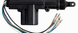
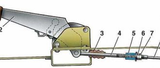
Lock activators are not called by any name, so don’t be surprised by so many names. We will stick to this term. The central locking solenoid most likely refers to an electromagnet, which is most often installed to open the trunk. In terms of power (traction force) it is much stronger than plastic activators, but it is also more expensive.
The approximate price for a regular central locking activator with 2 outputs (two-wire electric lock) is 100-120 rubles. a piece. For 2 doors you will need two activators, the total cost is about 250 rubles. The kit for each activator includes a special strip for attaching the central lock and self-tapping screws, as well as a rod, screws and a metal retaining plate.
3) To save insulating tape, it is advisable to take copper wires in general insulation around the insulated conductors, but you can also buy them separately (single-core). The cross-section of the conductor must be at least 0.75 square. The current consumption of a conventional electric central locking drive can reach 5A at its peak.
In auto stores you can choose wires of various diameters, colors and lengths. Some are sold in ready-made installation kits or kits. Individually or “by meter,” most often, single (single) wires are found.
We recommend going to a regular electrical supply store and purchasing a two-conductor copper cable (the individual wire of which has a stranded conductor). For example, a PVS 2×0.75 cable (with a polyvinyl chloride sheath) or a PVS 2×1 mm cable is suitable. These wires are used to connect various electrical appliances, power tools and other machines and devices. The cost is about 12-15 rubles per 1 meter.
You can look for special automotive PGVA wires, which are intended for automotive equipment and instruments. They also have polyvinyl chloride insulation and are undoubtedly suitable for connecting central locks.
When installing additional devices and using a second alarm channel, carefully study the table with permissible current loads. Most likely, to install a powerful solenoid that will open the trunk lock, an additional unloading relay will be required.
Plastic tape clamps will be needed to secure the wires. Purchase at will, 10 pieces will be enough.
A set of 100 pieces measuring 2.5×100 costs about 50 rubles.
5) Other tools, devices and materials that may be needed during installation.
Possible malfunctions of the vacuum central locking
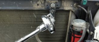
During periods of intense precipitation, as well as when the air temperature drops, interruptions in the operation of the central locking pump occur. The reason, as a rule, lies in the appearance of condensation, which occurs when there is a sharp temperature change. There is a malfunction of the contact of the driver's door actuator switch. The solution to this situation is as follows: the switch is dismantled, condensation is removed and the working surfaces are lubricated. In some cases, it is necessary to completely change the mechanism.
Door locks operate asynchronously, that is, not simultaneously.
Sometimes on some doors the locking mechanisms do not work the same way or do not work at all, this may happen with some delay or not at all, as a result, the doors continue to remain open, even after the remote control has given the command to lock the doors. In this case, the compressor can continue to operate until the protection system turns it off. In such cases, the tightness of the connections of the vacuum tubes of the line is checked, as well as an inspection of the door line on which a similar phenomenon is observed. The search for damage is carried out by visual signs, as well as by ear, by the characteristic hissing of air being released. If damaged areas are found, repair or complete replacement should be performed.
The electrical wire in the door corrugation is damaged
The signals are sent to the pump control board, but it still continues to work, ignoring these commands. Such breakdowns require disassembling the compressor unit with subsequent cleaning of the oxidized terminals of the pneumatic sensor of the alarm system. If after the measures taken the situation has not changed, it can be assumed that the pump control board has failed.
Fixing the problem
Even a short-term loss of power to the microcircuit inside the key fob can lead to synchronization disturbances in the operation of the entire central locking unit. This will require new firmware for the remote control. This requires the intervention of specialists and a special training key. On the other hand, you can try to solve the problem on your own.
What can be done on site
You can restore synchronization as follows:
- turn on the ignition using a key that requires restoration;
- wait at least 6 seconds;
- turn off the ignition after the immobilizer stops flashing.
After 10 seconds, use the same key to start the car. An indicator of a solution to the problem will be an extinguished immobilizer indicator.
If the central locking system malfunctions, the key fob is in good working order, then you can try replacing the system fuse and loosening the screw on the key fob.
In various situations, it is important to choose the right solution to the problem:
- The car does not lock in the cold. In such cases, you can use a hairdryer to warm up, dry the lock, and lubricate it with non-aggressive penetrating compounds such as WD-40. In some cases, it is necessary to disassemble the mechanism and replace worn parts.
- It is impossible to lock the car. This may be due to sagging doors or the lock being displaced after an accident. This requires mechanical adjustment using bolts.
- The door doesn't close all the way. This problem can arise due to the lock freezing, a violation of the geometry of the hinges, or the rack. Under such circumstances, you can even out the deformations, set the required gaps, clean and lubricate the lock.
Features of electric lock repair
This may require replacing the relay, coil, actuator gear, restoring a separate contact, or repairing the electrical wiring. If the break point cannot be found, then you need to check the limit switch.
In addition, you should check the solenoids, since these elements can fail due to sudden temperature changes and high humidity.
Possible malfunctions of the locking system
If there is no reaction when you turn the key in the lock or press a key on the remote control, this means that the central locking is not working.
All causes of central locking malfunction can be divided into two types:
- technical;
- related to climatic phenomena.
In the first case, breakdowns are possible due to incorrect installation or configuration of the locking system. Subject to natural wear and tear after long-term use. The service life directly depends on the quality of the device.
In the second case, the central locking system may fail under the influence of low temperatures and it may freeze. The lock may not work if water gets into the mechanism during rain or melting snow.
The central locking system may not work due to an incorrectly installed or faulty alarm system. In this case, you should diagnose the locking system. The control activator is installed in the driver's door. As soon as the drive is activated, signals are sent through the appropriate channels to the remaining activators, according to which the required action is performed. Therefore, you should check the operation of the lock using the key and the button on the key fob.
If the doors sometimes close, sometimes they don’t, then the reason may be in the control circuit or a violation of the integrity of the electrical circuit of the car alarm. The reason why the central locking system fails to operate may be insufficient battery charge or a blown fuse. Depending on the circuit being used, there may be multiple fuses. They all need to be checked and faulty ones replaced.
The fuse can burn out as soon as it is installed, due to a short circuit or overload, for example, when controlling the central locking with a key fob, and not manually. In warm weather, the reason is a short circuit, which is possible due to poor contacts or an open circuit. The cause of the breakdown may be a malfunction of the central locking control unit.
You can check the operation of the unit using a multimeter by checking the power supply to the activators. Current is supplied to the contacts of the unit by unlocking and locking the driver's door. If the control unit is broken, it needs to be replaced.
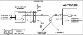
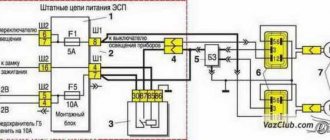
Central locking diagram for VAZ 2114
The system consists of the following components:
- mounting block;
- 8 amp fuse;
- 4 gearmotors (one in each door, and the one in the driver's door has a contact group);
- central locking control unit;
- wires (red, black, blue, yellow) and plugs;
- rods that are located in each door;
- limit switches that signal the current state of the door (open or closed).
Let's make the alarm system and central locking together
Any modern alarm unit is equipped with two relays connected to the central locking control unit. One relay is opening, the second is locking, and the circuit in the general case looks like this:
Control of central locking by supply of “mass”
In our case, the green and white cords coming from the signaling unit will be required, as indicated in the diagram. However, they will not be the only ones needed. We will connect the relay contacts to breaks in the standard wiring. This means there will be not 2, but 4 cords.
Connection diagram for VAZ central locker
Take another look at the diagram published in the first chapter. We will connect the relay to the gap in the white and brown wires going from the microswitch to the central lock control unit. And it is obvious that it is easier to break these wires near the 8-pin connector. The same one shown at the beginning.
To avoid any questions, we will show you what should happen as a result:
Connection diagram, central lock VAZ
The common contacts are connected to the wires coming out of the microphone. The white cord continues with the brown wire coming from the door, and so on. Normally closed contacts are also used, along with normally open ones. These are the features of connecting to the VAZ central locking system.
An approximate sequence of actions performed by the installer:
- Make and lay a 4-core cable running from the signaling unit to the 8-pin connector;
- Connect the cable on the side of the alarm unit (see the last diagram);
- Near the 8-pin connector, disconnect the white and brown wires coming from the microswitch (pins 5 and 7). The main thing is not to confuse them with the wires going to the triangular connector “C”;
- Make connections to the broken wires, white and brown. That's all.
We have given this sequence to emphasize once again that the relays are switched on between the microphone and the central lock control unit. There is no need to connect any additional devices. As a result, the alarm system will be able to control the state of the locks.
All wires added to the car structure must be protected (use heat-resistant tubes or electrical tape). Twisting is not the worst method to connect two wires. But it's even better to use soldering.
An interesting nuance from practice
It would seem that if a person has experience working with electrical equipment, he can do everything according to the instructions given. As a result, if no mistakes are made, you may encounter an interesting phenomenon. Instead of closing, there will be a short-term locking followed by opening. And vice versa. What to do in this case?
Take a look at what exactly may be present in some of the configurations:
Cheaper - no driver actuator
The driver's door may not have an actuator. And then, it is useless to connect the signaling system to the control unit. There is no actuator, which means there is no one to close or open the door and move the microphone lever. Let's say the locks are closed, and then we remove ground from the brown wire and we get the following: the white wire is on ground, unlocking occurs.
We note the following: installation can only be carried out when you are sure that there is an actuator in the driver's door.
There were configurations where only a microswitch was installed. There is no need for arrogance here - adding an actuator will be difficult, since standard wiring must go to it. As you understand, it may not be available from the factory. And it’s unclear what to do then.
There remains one unanswered question - where exactly the central locking control unit is located. In these VAZ models, if there is a central locking system, then there is also a control unit. And it is located under the torpedo cover, next to the driver, on the right:
VAZ-2110, BU TsZ
We remove the “beard” of the torpedo and look at what is on the upper right. On the same plane with the radio connector there are two boxes attached - the one we need, as well as the immobilizer (if there is one).
We would be lying if we did not say that in reality there is another option for installing the alarm. Standardly, only two power cables go to the actuators. Having a power outlet equipped with a fuse, these cables are connected directly to the alarm relay. This option, as you might guess, is not recommended. Imagine what would happen if the alarm system broke. The central lock must remain, but in this case this will not be done. Happy connection!
How well do central locking and alarm systems work together in VAZ-2110 cars?
As you know, a modern alarm system involves autonomous control of all opening parts of the car. For this reason, it is possible to connect the VAZ 2110 central locking system to the alarm system. The connection diagram for the signaling device is included in the operating instructions for the device. The central locking control circuit also seems to have an additional unused connector for this purpose.
However, in reality it is not so simple. Control signals from the alarm system to the central locking system will conflict with the information received from the limit switch installed in the driver's door. For this reason, the standard central locking control circuit with which VAZ 2110 cars are supplied from the factory should be slightly altered.
How the central lock works
The central locking algorithm consists of sending an impulse to the VAZ 2114 central locking control unit, which analyzes the received signal and generates commands that control the door locks. They are either opened or locked.
General scheme of central locking
Elements that activate the central locking are connected to pin 30. If contact 87 closes, then the activator outputs will be affected by ground. When a certain relay 30 is activated, the contact will connect to the positive. Thus, the activator will receive power and the rod will begin to move. The control unit rod closes different pairs of signals depending on what action needs to be performed: closing or opening the doors.
Since the central locking activators are connected in parallel, all doors will either open or lock at the same time. Central locking can be pneumatic or electric. The first type of device includes a control panel, compressor and tubes. In an electric one, the main element is a motor, thanks to which the mechanisms are activated.
Problems in the operation of the activator electric drive
The central locking actuator is quite fragile and does not tolerate overload. The activator body, made of plastic, can easily melt if the frequency of door closing is excessively high. The duration of the control pulse also plays an equally important role. Try to always remember about the extreme fragility of the activator and not to load it during operation.
It is easy to guess that the activator is located in each individual door of the car. If the body of one of them melts due to overheating of the electric drive commutator, this becomes the cause of many problems:
- the activator on individual doors stops functioning;
- Constant overloads in a jammed electric drive cause the fuse to fail.
Settings
After the alarm system on the VAZ 2114 is fully connected, its final configuration should be performed.
It is carried out as follows:
- Disable security.
- Set the ignition key in the lock to o.
- Press the button labeled Valet 6 times in a row.
- After the step marked “3”, immediately turn on the ignition (6 beeps should sound).
- Using the Valet button, select the required function (their list is given in the table below). To set it to the required value, press the corresponding key on the alarm key fob.
In this case, the most optimal (recommended) settings will be the following:
- for function 12 - value 3;
- for function 11 - value 4;
- for function 9 - value 3.
You can check whether the alarm is connected and configured correctly as follows:
Disconnect the yellow cord coming out of block A91 from terminal 15 of the ignition switch. Turn the ignition key and start the engine. Pay attention to the alarm LED - if connected correctly, it should blink continuously.
The last thing I would like to talk about today is the importance of correctly connecting the tachometer, which directly affects the operation of the autostart
To avoid errors, it is recommended to make this connection strictly in the following order:
- connect the red wire from the BUBD connector to the positive 12 volt terminal;
- connect the black wire of the 18-pin connector to the vehicle ground;
- Connect the gray-black wire of the same connector to the wire coming from the tachometer.
If you then turn on the ignition, then if the tachometer is connected correctly, the alarm indicator will begin to blink evenly.
Synchronization
It can disappear not only if the battery is incorrectly replaced, but if the open button is repeatedly pressed outside the operating range. If such a problem occurs, then you will need a special flashing key. Finding such a device is problematic, especially if you have the cheapest alarm system. So try the DIY synchronization method. To do this, turn on the ignition with the key and wait about 6 seconds. As soon as the immobilizer flashes, the ignition is turned off. After 10 seconds it is turned on again. If everything worked out, then the immobilizer should not react to this.
Also on all these cars the central locking control modules are connected via a fuse. Typically, 30 A flag fuses are used for these purposes. The fuse is checked either visually or with a multimeter. If the device shows that the resistance approaches infinity, then the fuse should be replaced. It's also a good idea to check the connector in the fuse box.
In all cars, the lock is driven by a motor. If one door fails, this motor should be checked. It may need to be replaced. Before doing this, be sure to check the wiring supplying power to the control unit. If everything is in order electrically, check the rods that activate the cylinder. Perhaps the rod has come off its mountings. You need to fasten it back.
Where is the Central Locking fuse on a VAZ 2110?
Many owners of cars belonging to the tenth family of VAZs, over time, have a question: where to find the standard fuse for the Central Locking ? This is due to the fact that the alarm system on the Ten, as a rule, is connected via the minus control to the standard central locking unit, and this fuse is constantly activated.
For some reason there was no place for it in the fuse block, but it is located in a cup tied with electrical tape to the wiring harness behind the fuse block.
Principle of operation
The central car lock consists of:
- central electronic unit;
- electronic units for front and rear doors (not always present);
- driver's door electronic unit;
- push-button switches for all doors;
- limit switches for closing windows and doors;
- control units and window lift drives.
In most cases, the units responsible for controlling the power windows are directly connected to the central locking and combined into a single system. When the doors are closed, the central locking checks the condition of all doors and windows so that they are not left open when closing and activating the alarm. The central locking system cannot be considered a separate element of the car. This is the name of all system components responsible for locking the locks in the vehicle. The task is to simultaneously open and close doors, raise and lower windows, and sometimes also be responsible for opening the fuel tank lid.
The principle of operation is based on the fact that when you turn the key in the driver's side door lock, a microswitch is activated, which is responsible for the locking process. From it a signal goes to the door control unit, and then to the central unit. From there, control signals are distributed to each of the available control blocks. This allows you to simultaneously close all doors, windows, etc. When you turn the key again, the reverse process occurs, that is, unlocking. Depending on the type of device, the central locking system can be triggered by contact or non-contact methods. The second option involves using a special button on the car keys.
Malfunctions
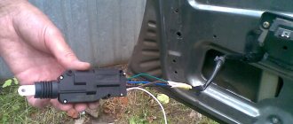
Good day everyone. In my last post I asked you for help and advice on repairing the central locking. Thank you all for your comments and responsiveness. Today in this post I will tell you how this problem was solved. So, initially the problem was that the car was armed, but the locks did not close. They also couldn’t be closed by manual pressing. It was decided to take everything apart and look. During disassembly, I found out that the driver’s door has a regular two-wire actuator, instead of the required 5-pin one. The remaining three contacts went to the lock itself; these were wires to the limit switch for the open/closed positions.
Full sizeThis is the actuator
Full size Here is the wiring to the central locking system, red and yellow are to the actuator, they alternately receive a signal depending on the position of the limit switch, the black wire is ground, and white and brown just transmit a signal about the position of the lock
Well, everything seems to be working at this stage. Forcibly applied to the actuator.
short term
+12V, short-term, otherwise there will be an overload and it will either burn out or the brushes will close. He's twitching, which means he's alive. I went further to look for the reason.
I thought that the wires might have frayed in the place where they enter the door. He pulled out the bunch, and for good reason. Some wires had broken insulation - I fixed it with electrical tape.
Full size If you look closely, you can see exposed veins.
Let's go further, I read that there is a central locking control unit. We need to find him now. I opened up the floor covering to see where the beam went.
As a result, I found the end under the heater on the driver's side of the connector and on it a circuit rewound with electrical tape. Even then I felt that there was probably a problem with it, but out of ignorance, I continued my search further.
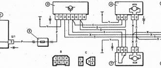
Full size Here is the old central control unit. As you can see, there are 6 wires coming here. Pink 12V, black ground, white, brown, yellow, red - I described them above. Here is the entire detailed wiring diagram, the colors matched.
Full size Central locking diagram for VAZ 2110, relevant for VAZ 2111 and VAZ 2112 In the end, I realized that all the signals reach this unit, there is power to it - but there is nothing at the output. That means it’s still dead. After shopping around, everywhere they offered me an 8-pin block, and only on the fourth day did luck smile on me and I bought the original 6-pin VAZ 2110 central locking block. It was immediately installed in its place, and I pressed it with bated breath signal - and hurray! closed, opened. Everything is as it should be!
Full sizeOld and new central locking blocks
Full size The connectors of the old and the new are identical. Well, since I’ve already taken apart a lot of everything, at the same time I tightened up all the masses. I also found two free two-pin chips in the same place in the driver’s feet under the stove. Maybe someone knows what they are for.
Full size Here they are in the distance, yellow and green, and purple and green, what kind of chips are they, tell me)
The well-known system, called central locking, as a rule, is not installed on all VAZ-2110 cars. Central locking is needed to simultaneously lock all car doors. This system is very convenient for the car owner. With one key you can control all doors. But, unfortunately, even such a system tends to break down. A large number of VAZ-2110 car owners face this. There are several reasons why the central locking may stop working or function incorrectly:
- Providing long or frequent pulses to control the opening or closing of doors.
- Central lock fuse is faulty.
- The plug connector has oxidized.
- Malfunction of the central locking control unit.
So, in order to understand the reason for the malfunction of the central locking, you first need to know what it consists of:
- electronic transistor control unit;
- actuators of the gearmotor (activator);
- limit switches;
- electrical wiring.
Types of faults
There are a lot of situations and cases when central locks on cars do not work. But it is important to understand exactly what happened and how the malfunction manifests itself. Mostly malfunctions manifest themselves in the form of a refusal to respond to certain commands. Sometimes the system opens completely. Mostly motorists are faced with the following situations:
- the castle behaves unstable;
- partial failure is observed;
- The central locking system does not respond to commands from the key fob;
- the system does not respond to commands from the key.
Each of the presented situations requires separate consideration.
Unstable work
There are cases when the central locks on cars have not stopped working, but their behavior and functioning can be described as unstable. That is, they can work normally when commands are given, but at some point give out unexpected surprises. Basically, instability at work manifests itself as follows:
- When the driver presses the key fob button, incorrect operation of the control unit or module is observed. The block either reacts to commands or completely ignores them and does not execute them. One time everything functions perfectly, no problems arise, but the next time there are failures. When sending commands to the central locking from the remote control, they may or may not be executed;
- When trying to open the door locks, at first the system opens them normally, but after a while it spontaneously locks them again. Although the driver did not give such a command. Locks can behave similarly when receiving a closing command. The doors lock and then unblock themselves;
- When the driver presses the button to open the doors, the control device closes them. And when you try to close the door, the opposite situation occurs, that is, the doors open;
- After pressing the open or close button, only part of the car doors carries out the command. One or more doors do not respond to signals, or perform actions opposite to the command.
It is obvious here that the central locking system really behaves unstable. Situations like this don't happen so rarely. But specialists will be able to find the cause and also help in restoring normal performance. Some car owners cope with the situation on their own.
https://www.youtube.com/watch?v=QwQIcpG2_iY
Partial failure
Here we are talking about situations when the central locks do not close, although it is possible to open the vehicle doors using a key or key fob. Here we are also talking about the fact that the central locking does not work, but this occurs in the form of a partial failure. If the driver tries to close the doors with the button, he will not succeed. Then you can close them mechanically, that is, by pressing the corresponding buttons from inside the cabin. After this, the key fob will normally unlock the doors, but will no longer be able to close them back. Such a malfunction indicates that the central locking system has partially failed. Here the problem should mainly be found in the electronics of the system.
Repair of electric central locking
After several years of operation, domestic central locking systems with solenoids begin to be afraid of downward temperature changes, especially in conditions of high humidity and in the autumn-spring period. The solenoids first begin to jam, and after some time they may completely refuse to open/close the lock. They are usually found on cars with a factory-installed central locking system. It is better to replace them with drives with a motor, but you can try disassembling them, cleaning them and lubricating them with fresh grease.
Failure to operate or partial activation of the activator of one or more doors can be caused by:
- a break or poor contact in the supply circuit from the driver's door activator switch to the power relay (directly or through the control board) and after it to the inoperative drive;
- relay failure;
- control board malfunction - if any;
- poor contact or broken wires at the terminals of the motor or solenoid inside the activator;
- wear of the activator gears (with motor) or its moving elements (for all drives);
- burnt motor winding or solenoid coil.
When opening, the voltage should disappear on this wire, and appear on the other. Then, depending on the test results obtained, either the activator itself is checked and the fault in it is eliminated, or the entire circuit before it separately (before the relay, including the control board, if any, then the relay itself and the wiring after the relay) restoring the functionality of the damaged areas . The most common breakdown in the central locking system is a wire break in the corrugation between the door and the car body.
https://youtube.com/watch?v=8CIlefaFLcw
Home →
Maintenance and Repair → Repair →
Problem in the operation of the central locking electrical circuit on VAZ cars
The first possible problem follows smoothly from those mentioned in the previous section. Overload in the operation of activators leads to an increase in the operating current in the supply circuit above the rated value. As a result, the fuse blows and the central locking of the VAZ 2110 simply “dies”.
It is by checking the fuse that the diagnosis of central locking malfunctions begins. By the way, it is located in a very specific place and it is not easy to find it right away even if you know where to look. In order to get to it, you will need to fold back the central panel with the fuses and dig into the entire wiring harness in the niche that opens behind it. The “comrade” you need is packaged in a special plastic cup and connected to the pink wire.
Central locking unit VAZ 2110
Another very common and obvious problem is the central locking connector. It is located in the most unfavorable place for this in the interior body, under the foot mat. A large amount of moisture and dirt inevitably gets there. Electrical contacts are intensively oxidized. As a result, the power supply circuit involuntarily breaks at the point where the plug connector is connected.
The front door of the VAZ 2115 does not open from the outside
How to Open the Rear Door on a VAZ 2114 The door does not open from the outside in any VAZ-2114 Step-by-step troubleshooting Opening a jammed lock VAZ 2114, 2115, 2113 The rear door of a VAZ does not open, how to remove the door trim on a VAZ 2110, 2111, 2112, Lada Priora Replacing the leash Method of opening the door Causes of malfunctions Troubleshooting
What to do if the door does not open from the outside
VAZ-2114
The door does not open from the outside in any VAZ-2114
Infrequently, but still, the owners of the VAZ-2114 have a problem - the door does not open from the outside. It is possible to eliminate this problem without the help of 100 employees, if you take into account the advice of experts when working and do the whole process step by step.
It should be noted that both the driver's front and rear doors can become jammed in the car. Before you begin to fix the problem, you should find out the cause of the breakdown. The door may not open properly due to the following circumstances:
- The car door button is faulty.
- The leash has become unusable.
- The rod has become disconnected from the car lock.
Having found out the cause of the breakdown, you can begin to eliminate the problem step by step.
Step-by-step troubleshooting
Work begins with replacing the button. Installation of a turbine on a VAZ 2114 8 valves, instructions and diagram. If it is made of silumin, then in the winter season such an element often freezes. How to raise the rear suspension on a VAZ 2110, 2112, 2111. To do this, you need to install spacers.
If you press hard, the silumin button may simply break. How to disassemble the door of a VAZ 2114 and remove the trim? Front and Obviously, such a part needs to be changed, but for this you can not take the assembled door handle on the VAZ-2114, but purchase a repair kit. How to change rear brake pads on a VAZ 2114 - luxvaz.
It includes:
Opening a jammed lock VAZ 2114, 2115, 2113
Rear lock jammed
right door VAZ
2115. The prerequisite was frozen water in the outer castle. how to open a jammed door on 21115 from the inside. I decided to clean the door locks on the car. The result justified itself VAZ 2115,2114,2113,2199,2109,2108 - duration 4 33. Until then.
The back door of a VAZ does not open, how to remove the door trim on a VAZ 2110, 2111, 2112, Lada Priora
DOOR ON VAZ DOESN'T OPEN
. HOW TO REMOVE DOOR TRIM
IF
THE DOOR
DOES NOT OPEN ON
VAZ
2110, 2111, .
- two keys;
- two leashes for handles;
- fastening elements.
Radiator grille with grant
Before replacing, you need to pay attention to the appearance of the element - on its reverse side there are two protrusions, one of which, when activated, will press the key, and the second is shortened during assembly so that the ends of the leash do not protrude outward
Replacing the leash
If, during inspection, the car owner discovers that the driver's door does not open from the outside due to the disconnection of the rod from the lock, then there is no need to buy additional elements. And the breakdown is repaired in the following sequence:
- the door needs to be opened
, carefully remove the inner lining of the door handle; - fasteners are unscrewed using a screwdriver;
- the window lifter handle is removed;
- the fasteners securing the door trim are removed;
- use a screwdriver to unscrew the button that activates the lock;
- the cladding is completely removed;
- the handle pull wire is disconnected from the lock;
- the fasteners securing the handle to the car door are unscrewed;
- Through the opening that appears in the door, the handle is carefully removed, and the traction wires are installed in a permanent place.
What kind of malfunctions can there be?
When closing the lock on the door, no other actions are noted. But if you even slightly need to try to open it with the key, the door can open immediately. The presence of malfunctions is immediately visible here. The main ones can be highlighted. The central lock opens and closes itself on a VAZ - this is a normal state of affairs, but if it is faulty
The contact does not open in the central locking drive
The contacts do not open in a timely manner, and this occurs due to the following reasons:
- Traction control. Structurally, it works like this: the lock button and the drive are connected together. In this case, the rod acquires the wrong position, and there is no contact with the electric drive.
- When the button touches part of the casing. The element is not lowered to the required depth in order to contact the electric drive and the traction. There are no signals to other doors.
If there are problems of this kind, you need to make sure that the position of the button is fixed at the very end. If this is not observed, then it is worth checking the casing and making sure that there are no scuffs, only then pay attention to the ideal, even and accurate position of the rod.
Fuse failure
If the central locking on a VAZ does not work, then the cause of this circumstance may be a blown fuse. If the driver tried to open the door, but this did not lead to the desired result, then you need to look at how the electrical circuit works, and more specifically, the fuse. This element can quickly fail and the cause will be not only a short circuit, but also even the smallest load.
The central locking does not work: signs of malfunction and causes of their occurrence
It happens that when the central lock located on the driver's door is closed, no action occurs on the other doors. However, as soon as you move it a little, the doors immediately closed. It is immediately clear that the problem here is the presence of malfunctions in the central locking and several reasons contribute to this.
Among all the possible causes of malfunctions, all the most basic ones can be identified.
No contact in the drive
With such a malfunction, the contacts inside the control drive do not close the necessary contacts in time. This happens for several reasons:
- The adjustment of the rod that connects the lock button and the drive is done incorrectly. This reason contributes to the incorrect position of the rod and lack of contact with the electric drive.
- The button touches part of the casing and does not allow it to lower to the required depth to ensure contact of the traction with the electric drive. Despite the fact that the driver's door closes, no signal comes to the other doors.
Check the condition of the metal rod.
When such problems occur in the operation of the central locking, first of all you need to make sure that the button is lowered to the very end. If for some reason this does not happen, first inspect the casing for burrs, and then inspect the rod for its even and accurate position.
Fuse blown
If manipulations with the central locking rod do not bring any results, and they do not react in any way to either opening or locking, then first of all you need to check its electrical circuit, and specifically the fuse. Because on the central lock it can fail not only if a short circuit occurs in the circuit, but also if the slightest overload occurs.
The central locking fuse is indicated by a marker.
Overload occurs most often from insufficient position of the rods, as well as lubrication in them during winter operation of the car.
The central locking wires are broken
Broken wires are not the main reason, but one of the reasons for the failure of the central locking system. The main reason for this is the break in the wires in those places where they bear the greatest load. Such a place is definitely the passage of the corrugation from the side of the pillar and the driver's door. And since it is the driver’s door that is most often opened in any car, it receives most of the load.
- It is quite easy to identify such a malfunction; you just need to release one of the ends of the corrugation through which the wires pass into the door and pull one of the five central locking wires. As a rule, they are connected into one bundle, or go next to each other.
- After carrying out such manipulations, a wire that is torn or broken will easily give in among the general heap.
- If you are absolutely sure that a particular circuit is faulty, replacing it will not be difficult by inserting the required wire and further insulating it with electrical tape.
- When the wires are broken or torn in other places, the fault can only be found by testing the circuit with a multimeter.
Block burned out
Another reason why the central lock may fail is a burnout of the central locking unit. And in order to diagnose it, you need to use the above-mentioned multimeter and determine the presence of voltage at the contacts of the block.
This is what the immobilizer and central locking unit look like behind the instrument panel.
Please note that during diagnostics it is necessary to operate the lock in the driver's door so that impulses are sent from it to the main unit
The central locking activator is faulty
And the last reason why the central locking refuses to work is the failure of the activator on the central drive. It can fail both for mechanical reasons, due to wear of rubbing parts, and due to the influence of external factors of moisture and corrosion.
Causes of problems and solutions to problems
Previously, only signs of malfunctions were considered. Now it is important to understand why they arise, who is to blame for this and what needs to be done in a given situation. Central locking failure is usually associated with:
- relay failure;
- wiring problems;
- battery;
- fuses;
- keychain;
- control device;
- actuator.
Considering the fact that there are many causes of malfunctions, each of them requires separate consideration. After all, the approach to repairing the central locking system directly depends on who was the culprit of the malfunctions. Motorists should be warned in advance. If you are not confident in your own strengths and capabilities, and do not have experience in repairing complex systems such as central locking, you should not try to repair the central locking system yourself. This is sometimes a complex procedure that requires appropriate qualifications and a clear understanding of the structure of the entire system.
Relay
A fairly common cause of malfunctions in the operation of the central locking system, when the car central locking does not open from the key fob, is the relay. Therefore, the motorist needs to check its current condition. You can do this yourself, since the procedure is not the most difficult. First you need to find the place where the relay is located. It may vary depending on the make and model of the vehicle. In some cars, the relay is installed together with other relays and fuses in a special block. But sometimes the element is located on the section of the electrical circuit that follows from the control unit. You can look at the instruction manual and find out exactly where the relay you are looking for is. Having found it, it is necessary to dismantle the device for further inspection. Checking is carried out with a multimeter. You can also disassemble the relay and check the condition of the board, which is located inside the case. If there are traces of burnt contacts, it will not be possible to restore the relay. It just needs to be changed. Experienced drivers and specialists recommend trying to close the electrical circuit directly after dismantling. If nothing has changed, all that remains is to simply throw out the old relay and put a new element in its place. It is inexpensive, but in a few minutes you can fully restore the operation of the central locking system. When choosing a new relay, it is recommended to take the old failed component with you. This will allow you to accurately select a similar device.
Wiring
Most often, electrical wiring suffers in the area that runs between the body and the door. It provides for the use of rubber corrugation, and wiring runs inside it. If it is damaged or interrupted by accident, or during active use, the central locking system will cease to function. When the circuit is open, due to the bending of the line, the contacts are closed, which allows the lock to function normally. Once it is closed, the contacts will open and the device will stop working. To solve the problem, it is recommended to follow a few simple rules.
- Open the car door. While it is open, press the close button. To do this, a rod in the form of a screwdriver or other available material is inserted into the lock latch from the end side. If everything is fine with the wiring, after such manipulation the lock should work and try to close the door
- Next you need to press the limit switch. He is in the doorway. This is necessary for the control module to record the fact that the device is closed.
- The car's security system is turned on if it has an alarm system. In this case, the door locks must be closed. If the alarm determines that the locks are closed, the driver will receive a response in the form of a sound signal.
- On the control panel, press the button to enable or disable the protection. If the door opens after pressing, pull the door handle, open the latch and slam it back. In a situation where the doors did not open, you should start looking for damage on the electrical line, that is, in the wiring.
MAIN PANEL ELEMENTS
The main place on the dashboard is reserved for the tachometer and speedometer, the fuel quantity sensor and the current fluid temperature in the cooling system. Let's look at the main symbols on the VAZ 2114 panel in more detail.
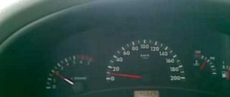
Tachometer
The VAZ 2114 tachometer is a pointer device, the signal to which is sent by the on-board computer of the fourteenth. The tachometer displays data on the number of revolutions of the crankshaft at the current time. The tachometer is divided by scales into 5 units, every second of which is digitized. The maximum numerical value of revolutions is 80.
To find out the actual engine speed when the car is moving, the tachometer indicator must be multiplied by 100. For example, if the arrow is located at 40, then the crankshaft is performing 4000 revolutions per minute.
The manufacturer has indicated a critical speed value, upon reaching which the engine of the fourteenth may fail due to excessive load. It is highlighted on the device with red shading; this value ranges from 6000 to 8000 rpm.
Under the tachometer there is an electronic window, which displays data about the current time and ambient air temperature.
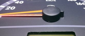
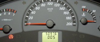
Speedometer
The fourteenth has an induction dial speedometer, which is located on the right side of the dashboard. The speedometer is also divided into sectors, the division size is 10 kilometers. The maximum mark is 200 km.
The speedometer operates from a speed measurement sensor located inside the gearbox. It is worth considering that all induction speedometers, including the one installed on the fourteenth, have an acceptable error level of 5 km/h.
At the bottom of the speedometer needle there is an electronic screen on which you can see data on the total mileage of the car and the mileage from the last starting point. The driver himself can set the starting point; for this, under the number 200 on the speedometer there is a manual switch that resets the current mileage count to zero.
Gasoline quantity sensor
On the right side of the instrument panel of the VAZ 2114 (the instrument panel of the VAZ 2114 and the designation of the indicators on the instrument panel of the VAZ 2113 are completely similar to the fourteenth model) there is a dial gauge for the current amount of fuel in the gas tank.
The sensor scale is divided into three marks: 1 – full tank, ½ – tank half full, 0 – empty tank.
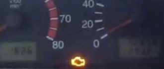
Next to the sensor there is a color indicator - a light bulb that lights up orange when the fuel level is close to a critical minimum. When the light comes on, you need to refuel the car within 20-30 kilometers.
Cooling system fluid temperature sensor
The coolant temperature sensor is divided into gradations of 20 units. The minimum temperature is 50, the maximum is 130 degrees. The critical temperature zone starts at 105 degrees and is marked with red shading.
If the coolant of the fourteenth boils, then you must immediately stop the car and turn off the engine, since driving in this mode is fraught with serious troubles, even complete engine failure.
If the temperature sensor on the VAZ 2114 dashboard does not work, you need to check the wiring through which the sensor is connected to the coolant container. It is also possible that the sensor contacts may oxidize; they must either be wiped with a solvent or the sensor replaced with a new one.
VAZ 2112 fuse diagram
With an 8-valve and 16-valve engine, it is equipped with a main mounting block, and since 2008 an additional console has been added. A diagram with element markings is printed on the left side of the main block cover and placed below.
The designations of all elements are presented below. You can find the transcript in the table.
| Circuit breakers | Power, A | What protects |
| F1 | 5 | Lamps for turning on the license plate lighting, instruments, side lights, trunk, left side. |
| F2 | 7,5 | Low beam |
| F3 | 10 | Further |
| F4 | 10 | PTF |
| F5 | 30 | Door windows |
| F6 | 15 | Portable lamp (socket) |
| F7 | 20 | Engine cooling fan. Sound signal. |
| F8 | 20 | Rear window heating element. Relay for turning on the heated rear window. |
| F9 | 20 | Recirculation valve. Cleaners, windshield and headlight washers (wiper fuse). Relay for turning on the heated rear window. |
| F10 | 20 | Spare |
| F11 | 5 | Starboard side marker lamps |
| F12 | 7,5 | Middle left |
| F13 | 10 | Far left. Power indicator lamp |
| F14 | 10 | Left PTF |
| F15 | 20 | Electrically heated seats. Trunk lock lock |
| F16 | 10 | Turn signals and emergency lights. |
| F17 | 7,5 | Interior lighting. Ignition switch. Stop signal. Watch. |
| F18 | 25 | Glove compartment lighting. Heater controller. Cigarette lighter fuse. |
| F19 | 10 | Locking door locks. Relay for monitoring the serviceability of brake light lamps and dimensions. Direction indicators. Reversing light. Generator excitation winding. On-board control system display unit. Instrument cluster. Watch. |
| F20 | 7,5 | Rear fog lamps. |
Relay
- K1 - lamp health monitoring;
- K2 - windshield wiper;
- KZ - direction indicators and emergency lights;
- K4 - switch on low beam;
- K5 - high beam;
- K6 - additional relay;
- K7 — heated rear window;
- K8 - rear PTF.
Starter fuse and relay
Installed on the device itself between the engine and the fan radiator. If signs of a malfunction appear, it is better not to delay replacing the element and install a new relay.
Fuel pump fuse and relay
Located in the additional interior installer - No. 3. Responsible for the fuel pump relay No. 5.
Relay and fuse for cigarette lighter
No. F18 is rated at 25 Amps.
Stove
The 25 A element F18 is responsible for protecting the operation of the electrical circuit of the heater motor.
Turn signals
The elements are marked as F19 and are rated at 10 Amps.
Brake lights
Located in the main block - No. F17. Its power is 7.5 A.
Where is the alarm fuse located?
No. F16 and rated 10 A.
Cooling Fan
The F7 element with a power of 20 Amperes is responsible for its protection.
Which fuse goes to the radio?
This is an F4 rated at 20 A.
Window lifters
F5 at 30 A.
Fuse and relay for central locking VAZ 2112: where is it located
They can be found in a separate box behind the main mounting block.
Ignition
The main relay is located in the additional cabin unit, where it is number 6.
Reverse
F19 with a rating of 10 Amperes is responsible for the lamps.
Fogs
Protected by three inserts: right - F4, left - F14, and rear - F20. The power of all PTFs is 10 Amps. In case of tuning, you may need to replace them with new ones along with the fog lights. The connection occurs via switch K8.
Lamp health monitoring relay
Marked as K1 in the main block of the VAZ 2112.
Brake
Installed under the brake pedal.
Relay and fuse for injectors
The additional element F3 is rated at 15 Amps.
Fuse for interior light
The F17 element with a power of 7.5 A is responsible for the safe operation of the VAZ 2112 interior lighting lamp.
Number plate illumination
Corresponds to F1 with a rating of 5 Amps.
Generator
A three-level relay voltage regulator is located on the device. It is better to replace the factory element with a new one, since three-level voltage regulation often leads to a short circuit.
Heated rear window
Relay K7 is responsible for turning on. Protects the F8 electrical circuit with a rating of 20 Amps.
Seat heating
It is protected by a 20 Amp F15 insert.
Wiper relay
This is a K2 and without its stable operation there will be no washer supply to the windshield, and the wipers will not be able to do their job.
Charger
They placed it next to the device - one of the few elements of this kind under the hood of a car.
Low and high beam VAZ 2112
It is protected by fuses F2 and F12 (left and right headlights), and the high beam is protected by F3 and F13 (left and right). The first has a rating of 7.5 A, and the second has a rating of 10 A.
Fuse for the dashboard of VAZ 2112
Located in the wiring harness leading to the instrument panel from the battery.
Dimensions
There are 2 fusible elements - F1 and F11, left and right. The power of both is 5 Amperes. Factory fuses require replacement due to the fact that the dimensions often burn out due to their malfunctions.
Heated seats
It is protected by an element marked F15 for 20 Amperes.
VAZ 2112 speedometer fuse: where is it located?
He's gone.
Opening the trunk
This is an F1 and is rated at 5A.
Fuse F6
Responsible for protection against burnout of the car socket. Its rating is 15 Amperes.
VAZ 2112: fuse F17 blows
Most often, this element, which is responsible for interior lighting, fails due to a battery failure. Its power is 7.5 A.
Fuse F19
Responsible for protecting the brake light, reversing lights and dimensions.
Relay K1
An element of lamp serviceability, which in older versions is replaced by a jumper.
Relay K6
This is a reserve item.
Speed sensor
Located on the wiring harness leading to the device.
Repairing broken wires
As a rule, most often the wires break off or break in the corrugation of the door. This is due to the fact that the door is constantly opening or closing, and the wire insulation is quite thin. To eliminate the problem of broken wires from the rubber corrugation of the door, you need to slowly pull out one wire at a time that approaches or departs from the central locking unit for power or control. A broken wire can easily be pulled out of the total mass. You can connect the break using a simple connection using male-female terminals. If the break occurs in another place, it is necessary to test all wiring with a multimeter. When checking, it is worth remembering that voltage will be present on one wire only at the moment of opening, and on the other - when closing the central lock.