The situation is as follows: for no apparent reason the engine began to “trouble”, the thrust was lost, and the idle now does not even reach 500. I removed the high-voltage wires one by one, and so, there was no spark at all in cylinders 2 and 3. The engine is 16-valve, but without “individual coils”. The question is how to check the ignition module on a VAZ-2112 engine, and it is advisable not to remove it. Inside the module, in addition to the coils, electronics are installed. How can I check if it's working properly?
Ignition coils in the electronic circuit of Lada Priora
The ignition system on Priora differs from the usual traditional scheme of carburetor models. On old cars there was one ignition coil, and the direct distribution of impulses to the spark plugs was carried out by a distributor, which still needed to be configured correctly. On injection models of cars with electronic fuel injection, each cylinder has its own individual ignition coil, which sends an impulse to its spark plug for its cylinder.
The entire process is controlled by the ECU, an electronic on-board device, from which the signal goes directly to the short circuit. In order to correctly manage the injection process and timely send a signal to an electrical impulse, the ECU uses data from the following sensors:
- DPK - taking into account the position of the engine crankshaft, it supplies an impulse to the ECU;
- phase sensor - it signals the position of the camshaft, professionals call it a synchronization sensor;
- tachometer - from it a signal is sent to the ECU at what frequency the crankshaft rotates;
- Mass air flow sensor - by measuring air flow through the air filter, it determines the load on the engine at a given time;
- DTOZH - determines the engine temperature;
- DT is a knock sensor, its readings affect the ignition timing.
Under standard conditions, according to the ECU signal, the cylinders operate in the following cycle - 1 - 3 - 4 - 2. That is, the impulse for the spark arrives in those cylinders in which the compression cycle ends, before the valve opens, fuel is injected and a discharge occurs, detonation occurs and the cycle continues .
The ignition coil in the general ignition system plays the role of a low-voltage voltage converter from the on-board power supply systems, battery or generator, to high voltage. Specifically on the Priora, based on a signal from the ECU, it generates a high-voltage electrical pulse on the spark plug.
Ignition coil on PrioraStructurally, an individual ignition coil differs from a common short circuit:
- The primary winding, through which direct current flows, is located inside the secondary winding.
- There is an inner core inside the primary winding and an outer core around the secondary winding.
- High voltage, up to 40 kW, which is generated in the secondary winding, is transmitted to the spark plug not through high-voltage wires, as on carburetor cars, but through a tip, which consists of a high-voltage rod, a spring and a sheath that has insulating properties. In addition, there is a diode to quickly cut off a high-voltage pulse.
Individual ignition coils do not have any single, unified marking. Each manufacturer has its own designation system for electronic parts. Therefore, we must proceed from which short circuits are in greatest demand among Priora owners.
One of the most popular brands is BOSCH. These ignition coils are marked - 0 221 504 473 (also found 0 221 504 461). It is believed that such reels should cover 100 thousand kilometers without failure, although in fact this is not always the case.
Very often this happens due to the large number of counterfeit spare parts on the automotive market. Just ask how much an ignition coil costs for a Priora. The price of 1,150 rubles is not the highest, and they are sold in large wholesale for 850 rubles apiece. Of course, this is a tasty morsel for garage workshop dealers.
Interesting in this sense is the experience shared by one of the specialists who specifically studied this sensitive issue. He tells how the original IKZ differs from the fake one. He had a Priora and gave us examples of how to check the ignition coil:
- Under the casing there is a plastic housing.
- There is a “lightning” sign, as a designation of high voltage, near the mounting axle box.
- The surface of the plug is perfectly processed, the font on it is clear, it is applied using a laser, so minor melting is visible.
- The plant number is circled in an oval.
- The contact spring has tight coils made by the factory machine.
- The body is made of metal.
- The lightning bolt sign is missing.
- The surface of the plug is roughly processed, the inscriptions are stamped, the rubber tip lacks the date of manufacture, product number and Bosch brand name.
Device
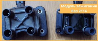
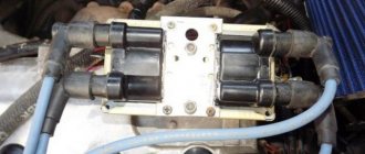
The ignition module has a common structure regardless of engine size. Inside the switch there are two high-voltage coils and an electronic circuit with many keys.
The coils are designed to switch high voltage and supply it to the spark plug to form a reliable spark in the combustion chamber of the engine.
The ignition module produces a spark in pairs, that is, each of the coils located inside the module is responsible for generating a spark on two cylinders: the first-fourth, the second-third.
- VAZ 2110 ignition module - check, replacement and repair
When is there an option to repair?
If during testing both secondary windings show integrity and serviceability, the reason for the inoperability of the coils may be a break in the soldering of the switch wires. Such damage is detected when the rear cover of the module is removed. If you have a soldering iron and know how to use it, you can restore the integrity of damaged contacts, while at the same time strengthening the rest. This, unfortunately, is the only failure of the ignition module that can be repaired.
Testing the ignition module can be done using simple do-it-yourself instruments. Based on our advice, you will be able to fully check both the module itself and other elements of the mechanism that may be the cause of the breakdown. We wish you success in this matter!
If you find an error, please select a piece of text and press Ctrl+Enter.
Didn't find the information you are looking for? on our forum.
None Many pelvic guides with 16 valves will understand me.
These are the ones on the 124 engine, there are individual ignition coils, one for each cylinder, the impulse is controlled through the ECU with also four keys. In general, a system of this type has quite a lot of advantages, since in the event of any malfunction, the brain turns off the faulty key. BUT in RUSSIA this system has a very decent disadvantage that completely outweighs all the advantages. Namely, low-quality ignition coils, factory coils last quite a long time and with timely maintenance (replacing spark plugs, preventing the generator from overcharging) they can travel more than 100 thousand km. But as soon as the factory ignition coils fail, dancing with a tambourine begins!
Factory coils usually burn out one after another with a difference of 300-500-1000 km. If one burns out, then wait for the rest of the corpses))) The cost of a new coil varies from 700 rubles (domestic manufacturer) to 1300 (imported by BOSCH).
Not cheap at all for the pelvis. But the saddest quality of purchased coils is that, like many components, it leaves much to be desired, and I encountered this problem within a year, I changed 5 pieces and they burned out before traveling 15,000 km.
I got tired of this and decided to switch to an ignition module like on a viburnum. two-winding coil with high-voltage wires. To do this, I needed the coil itself, high-voltage wires for 16 valves, a coil connection chip and brain firmware, which I stupidly didn’t know about and didn’t read enough about.
I’ll tell you how I made the transition in the next post.
In the meantime, the culmination is that having assembled the entire system and without flashing my brains, I began to start the engine, which later turned out to be unsuccessful. The first attempt pumped quite a bit of fuel into the exhaust, the second attempt ignited it. And there was a decent boom (in Russian, it was so bad that my ears were blocked for about three minutes, the hair on the mechanic’s balls turned gray “from his words,” I didn’t check it myself, the men on the street sat down on the ground). And it became somehow clear that such an explosion could not happen without consequences. As a result
Bombed fart thank you all! especially to the two guys who read the previous entry and reacted somehow. The rest of the 700+ robots who were squeezing are nice to you too! You encourage me to paint the BZ)))
In modern cars, individual ignition coils (ICO) are used to supply a spark to the cylinder. Older cars use ignition modules, meaning one module is entirely responsible for firing all cylinders. An individual ignition coil is responsible only for the operation of one cylinder in which it is installed. IKZ began to be installed on VAZ cars, starting with the Lada Priora car on the 126th engine. An ignition module is still installed on 8-valve VAZ engines. The car's on-board network uses low-voltage voltage, which is not capable of itself forming a powerful spark necessary for engine operation. Therefore, ignition coils are used to supply high voltage voltage.
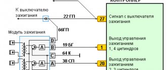
Connection diagram
The ignition module is part of the space under the hood, it’s easier to find it by the position of the high voltages, they go from the spark plugs straight to it.
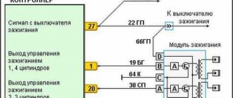
Ignition coil diagram:
VAZ 2114 ignition coil diagram
This diagram is good to follow when you have to replace the ignition coil of a VAZ 2114. In principle, everything is transparent: from contacts with the controller (ECU) to high-voltage wires. The name of the circuit is often common under the name ignition coil pinout: the pinout is a visual representation of the functionality of the device's contacts, which are numbered according to their purpose.
It can be connected in two different ways: when the ignition system coil is removed and when it is directly in its place in the car engine.
If you are holding the module in front of you:
- Let us recall the diagram: the first and fourth contacts are on one winding, the second and third – on the other (they are numbered in the diagram!)
- Then, the lower explosive contact (left) goes to the first cylinder
- On the second - upper explosive contact (left)
- The third cylinder goes to the upper explosive contact (right)
- On the fourth – lower explosive contact (right)
If the module is plugged into the engine, then pinouting the explosive contacts will be more difficult, because the device stands at an angle (as if in a diamond):
- We throw the central lower contact onto the first cylinder
- On the second - left contact
- We put the upper contact on the third cylinder
- On the fourth - right contact
Of course, the first installation option is more convenient, especially since the explosive wires require increased care in the nature of the connection (mixed up and won’t start, in the worst case, the entire engine system is ruined). Speaking to the point, it is clear that the connection diagram for the VAZ 2114 ignition module is not complicated.
By the way, buying an ignition coil is not a cheap pleasure; the price of an ignition module for a VAZ 2114 ranges from seven hundred to a thousand rubles, depending on the location of your city on the map of our country (for more information about how much an ignition module for a VAZ 2114 costs, you can find out by calling a disassembly service or a spare parts store, the running part is almost always in stock).
Video “Recommendations for diagnosing MH”
Important recommendations and features of diagnosing MZ in VAZ 2112 cars are shown in the video below (author - AutoElectrika Diary channel).
The car jerks, there is no traction, vibration is felt, or the engine is rough; all these are symptoms of improper operation of the individual ignition coil (IIC). Other signs of a faulty ignition coil are the presence of errors 0301, 0302, 0303 and 0304, indicating misfire in one of the cylinders. Let's look at a few simple ways to check the ignition coil with your own hands.
It is worth noting that the process of checking IKZ on modern Lada cars (XRAY, Vesta, Largus, Granta, Kalina and Priora) does not have significant differences. All actions are performed in the same way.
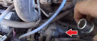
Removing the ignition module
To repair the VAZ-2110 ignition module, it must be dismantled. First, check if there is high voltage on all terminals. The most common breakdown is the lack of spark in the second and third cylinders. If you lightly press down on the rear of the housing, the engine can begin to operate normally. But it won't last long. To withdraw you need:
1. Disconnect ground from the battery.
2. Remove the decorative cover covering the block head, if any.
3. Remove all high-voltage wires.
4. Disconnect all wires going to the ignition module. The white rings indicate the numbering of all wires. On the body of the device there is a designation of cylinder numbers.
5. Disconnect the connector from the device.
6. Unscrew the three nuts securing the block.
That's all, the VAZ-2110 ignition module has been removed, and you can start repairing it.
Checking the Ministry of Health with your own hands
There are several options for checking the device yourself at home; let’s look at the simplest one.
To carry out independent diagnostics, you need to know what the wires connected to the module are responsible for:
- red-blue - provides 12-volt power to the device;
- the brown wire is ground, usually connected to the car body;
- white-blue - connects to the spark plugs of the first and fourth cylinders;
- the red-gray wire connects to the spark plugs of the second and third cylinders.
The process of removing and installing the IKZ - replacing the ignition coils of a Lada Vesta car
Algorithm of actions:
- Remove the wire with the “–” sign from the battery and take the “TorX E8” or 8 key.
- remove engine protection;
- by pressing the locking element, disconnect the inductor from the block;
- pull out the coil by unscrewing the fastening.
Installation is done like this:
- Using a two-millimeter roller, apply a special high-temperature lubricant to the inner surface of the tips.
- install the IKZ in the reverse order of removal.
Replacing a part, as you can see, is a simple process. Using these methods, you don’t have to go to a car repair shop, and if a breakdown occurs at a long distance from service centers, you’ll have to deal with it yourself. Having studied the methods of checking faults, you will be able to fix the breakdown yourself.
We hope this article will help you in such a situation.
The main reasons for the lack of spark
Not all motorists know the reasons for the loss of spark, much less methods for diagnosing and troubleshooting problems. So, it is worth identifying the main reasons, and then deciphering why exactly they become the cause. Finally, you need to consider ways to eliminate the defect. So, what reasons could cause the spark to disappear:
- Failure of the fuel pump.
- Spark plug.
- Ignition coil.
- High-voltage wires and their location.
- Gas distribution mechanism.
All the reasons have been found and it is worth moving on to the process of eliminating this malfunction.
Are you giving me a spark? Troubleshooting!
First of all, it’s worth noting that you don’t need to rush to check right away. As practice shows, there is a certain sequence of actions and malfunctions that could lead to loss of spark on a 16-valve engine.
Fuel pump
Ignition is not the first reason for the ignition failure on a car. Before getting into the electrical part of the car, it’s worth delving into the mechanics, so to speak. Turn on the ignition and listen to see if the gasoline pump is working. If it is silent, then you need to check whether gasoline is entering the cylinders.
It is worth starting the diagnostic procedure by checking the fuses for serviceability. Of course, you can only view the one that is responsible for the fuel pump (in this case, when you turn on the ignition, the pump will not pump), but it is recommended to diagnose everything for integrity. If at least one fails, it must be replaced.
If the previous procedure did not help, then we turn directly to the pump itself. For diagnostics, you will have to remove the entire module, which is located under the rear sofa, and disassemble it.
The pump itself is easy to check - the contacts are closed through the tester. If there are no readings, then the part has “died” and requires replacement. If the pump is “live”, then it is necessary to clean the contact group and check the wiring for breaks.
Spark plug
The candle becomes the second boundary, which may cause the spark to disappear. We unscrew the elements and carry out visual diagnostics. If everything is clean and beautiful outside, then you need to measure the resistance and check the gap. Of course, you can check the performance of a spark plug on a special spark plug stand, but not everyone has one in their garage. Therefore, we do everything the old fashioned way.
We connect the spark plug to a high-voltage wire, which is connected to 1 cylinder, and with the outer side to the body to obtain ground, and provide an ignition contact.
When performing this operation, you should be extremely careful, since the voltage that enters the spark can be fatal. Thus, we check all the spark plugs for the presence of a spark.
An alternative way to check spark plugs
Ignition coil
The ignition coil can be checked using a multimeter. If it is faulty, it is recommended to replace it, but there are brave souls who repair this unit. Of course, not everything always goes smoothly and often everything ends with one thing - the installation of a new one.
High voltage wires
A breakdown or failure of the wire will immediately become known as the car will start to shake. But, if the explosive wires are located incorrectly in the cylinders, then you will have to place them according to the connection diagram. The missing spark problem should go away.
The last place to look for a missing spark is the timing belt. Misaligned valve timing can be a problem. This could happen due to incorrect installation of the deposit disk. It is located on the crankshaft pulley and serves as a reference synchronizer for the sensor. If it is positioned correctly, when 1 cylinder is in the TTM, the sensor is placed between the 19th and 20th teeth. You can eliminate the cause by setting the disk correctly to the marks.
What you need to know when working with the module
Before working with the module, you need to purchase aluminum flux. When replacing transistors, please note that it is very difficult to solder wires to the collector terminals, since they are coated with a special material. And it complicates soldering. To make your work easier, carefully open the spray. Try not to overheat the element. Place it on an aluminum plate so that all the heat goes into it. Otherwise, the semiconductor junction will be destroyed and you will ruin an expensive element.
When soldering wires, make sure that their length is as short as possible. All soldering areas must be coated with varnish, even for nails. After repairs, be sure to check the functionality of the VAZ-2110 ignition module. If it functions normally, then it is necessary to treat everything inside with auto sealant. This will ensure maximum tightness of the unit - neither water nor dust can get into it. And such a device will last for many years. But if the problem does not lie in the contacts or power transistors, it is better to abandon the repair idea and purchase a new module - on a VAZ-2110 it costs about 1,500 rubles.
Performs one of the main functions in the ignition system (IS) as a whole. Thanks to this unit, the engine starts optimally, as well as its normal operation in the future. You can learn more about device malfunctions, as well as its replacement, from this material.
Checking the coil for VAZ 2101-2110
First, let's look at the sequence of checks on VAZ cars. Moreover, checking the carburetor for VAZ-2101 and VAZ-2110 is no different, the only difference is in the readings. Next is the verification process itself:
It is better to test the coil when it is removed from the car. Before starting removal, disconnect the negative terminal from the battery. From the coil we disconnect the wires from the side terminals, as well as the central wire. It is better to mark the wires from the side terminals so that they are not confused during installation. Loosen the coil fastening and remove it
Before checking with a multimeter, we clean it from dust and dirt, especially paying attention to the terminals. Then we inspect it for external damage. If there are any, further checking is pointless; it is better to replace it immediately; Checking the primary winding
To do this, switch the multimeter to ohmmeter mode and connect its probes to the side terminals. Different types of coils were used on different VAZ models, so you need to know which resistance readings are correct for them. So, for the B-117A model, used on classical models (VAZ-2101-2107), the resistance of the primary winding is Ohm. And on classic models with a contactless system, coils are used marked with this parameter being Ohm. On VAZ-2108-21099 cars, as well as VAZ-2110 carburetors, models with numbers - and 8352.12 are used. For the first of them, the resistance of the primary winding is considered normal in the Ohm range, and for the second - Ohm; Next, the secondary winding is checked. To do this, switch the multimeter to the kOhm measurement mode, leave one of its probes on the side terminal, and connect the second to the central terminal. For a working B-117A coil, the resistance of the secondary winding should be kOhm. For model 27.3705 this parameter should be in the kOhm region, for 3122.3705 - kOhm, and for 8352.12 - kOhm; The last thing to check is the insulation resistance. To measure this parameter, switch the multimeter to measurement mode in MOhm. To measure, we connect one probe to the coil body, and connect the second to each terminal in turn. When measuring this parameter on all specified models, the multimeter must show at least MOhm; If any of the parameters does not match the specified values, then the coil is faulty and must be replaced.
If there are any, further checking is pointless; it is better to replace it immediately; Checking the primary winding. To do this, switch the multimeter to ohmmeter mode and connect its probes to the side terminals. Different types of coils were used on different VAZ models, so you need to know which resistance readings are correct for them. So, for the B-117A model, used on classical models (VAZ-2101-2107), the resistance of the primary winding is Ohm. And on classic models with a contactless system, coils are used marked with this parameter being Ohm. On VAZ-2108-21099 cars, as well as VAZ-2110 carburetors, models with numbers - and 8352.12 are used. For the first of them, the resistance of the primary winding is considered normal in the Ohm range, and for the second - Ohm; Next, the secondary winding is checked. To do this, switch the multimeter to the kOhm measurement mode, leave one of its probes on the side terminal, and connect the second to the central terminal. For a working B-117A coil, the resistance of the secondary winding should be kOhm. For model 27.3705 this parameter should be in the kOhm region, for 3122.3705 - kOhm, and for 8352.12 - kOhm; The last thing to check is the insulation resistance. To measure this parameter, switch the multimeter to measurement mode in MOhm. To measure, we connect one probe to the coil body, and connect the second to each terminal in turn. When measuring this parameter on all specified models, the multimeter must show at least MOhm; If any of the parameters does not match the specified values, then the coil is faulty and must be replaced.
POPULAR WITH READERS: How to avoid falling asleep while driving, useful recommendations
A little about prices
We have already noted which switch and transistor are used when repairing the ignition module of a dozen. The first costs about 3 dollars, and for the second you will have to pay about 6 dollars.
Some craftsmen use a domestic analogue of the transistor - model KT848A. Of course, it costs less. But its problem is its lower quality and larger size, which somewhat complicates the repair process.
We recommend watching:
- Replacing high-voltage wires Kalina 8 valves
- After warming up the engine runs intermittently
- Zil 130 shoots into the carburetor reasons
- Expiration date of spark plugs
- Why doesn't the starter start?
- Why does the car jerk at high speeds?
Repair
So, for the VAZ 2110 the most common problem is the disappearance of voltage on cylinders 2 and 3. After some time, the engine starts working normally again if you press the rear plate of the module.
You should not put up with such a situation; it is better to immediately check the functionality of the unit, restore or replace it completely.
Removing the module
The procedure is quite simple.
- Disconnect the negative cable from the battery.
- Remove the plastic cover that covers the motor.
- Remove the wires from the spark plugs.
- Disconnect the wires from the ignition module. Their numbering is indicated on special white rings. And the cylinder number is indicated on the ignition module housing.
- Disconnect the connector from the ignition module.
- Using a 10mm socket, unscrew the three nuts that hold the block we are looking for.
- Carefully remove it, after which you can begin further work.
Now let's move directly to working with the module:
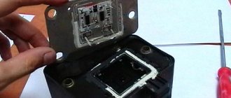
- Open the aluminum plate on the ignition module. A flathead screwdriver is useful for this.
- Inside you will find a small printed circuit board with electronic components. It is covered with a transparent layer of silicone, which will have to be removed.
- There are also wires that connect the board to the connector contacts. They are made of aluminum, so they can tear quickly.
- Tear off all the wires from the contacts, don’t be afraid. Others will be installed in their place. By the way, experts recommend using stranded wires used in computer mice.
- The ignition module circuit includes two switches and two powerful transresistors. If you decide to change these elements, you need to know that the switches are manufactured by SGS-THOMSON (model L497D1), and the transistors are of the BU931 type.
- The contacts are made of aluminum, so you will need a special flux to work with this metal.
- We solder the wiring to the board. It is more difficult to solder to the transistor collectors, since they are covered with a special material, the soldering of which is problematic. Therefore, try to hide the top coating from the element as carefully as possible. To prevent the soldering iron from transferring all the heat to the plate, place it on the stove and heat it to 180 degrees Celsius.
- Solder the wires to the contacts on the module so that they are as short as possible.
- Cover the areas where you soldered with varnish. Regular nail polish borrowed from your wife will do.
- Check if the ignition module is working.
- If everything is fine, coat the inner surface with a special autosealant, then reassemble in the reverse order.
- Upon completion of assembly, the wiring should be positioned fairly freely. Make sure that they are not compressed inside the box and that the integrity of the connections is not broken.
Carrying out such a repair of the ignition module on a VAZ 2110 with your own hands will not be difficult. But be careful, act carefully and consistently. Pay special attention to the soldering process.
If the cause of the malfunction lies elsewhere, then there is a high probability that it is better to simply replace the VAZ 2110 8-valve ignition module with a new one. The search may drag on without yielding results. Replacing the element will completely solve the current problem.
How to replace the ignition module on a VAZ 2110-VAZ 2112?
Note! Before you go to a car store for a new module, be sure to look at the markings on the old one, and in general remember for the future, almost all automobile parts have markings and therefore, before purchasing new parts, pay attention to the markings that are applied to the old ones and according to the same markings and buy new spare parts. So let’s get back closer to the topic, there are also some markings on the module, so before going to the car store, look at what they are and write them down on a piece of paper or somewhere else, and already in the store, forge a new module for your car of the same type as the old one module!
Removal: 1) At the very beginning of the operation, although many car owners even neglect this, it is imperative to disconnect the “negative” terminal from the battery terminal, just so that suddenly a short circuit does not occur due to moisture or anything else, which could would destroy the wiring in your car. (For information on how to disconnect the “-” terminal from the battery, see the article entitled: “Replacing the battery,” point 1)
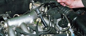
2) Then grab the high-voltage wires with your hand and disconnect all of them (there are only four) from the module.
Note! For clarity, in the photo above the module has already been removed from the car and is simply lying on the engine with the wires connected to it!
3) Next, disconnect the block of wires from the module, to do this, simply grab it with your hand and press the latch that you will feel on this block with your hand in its lower part, and then simply remove this block and put it somewhere so that it does not interfere.
4) Then you have two options: either remove the module together with the bracket (Sometimes this is done in order to get to any other parts, for example, the coolant drain plug from the cylinder block) or remove it completely separately, this is more convenient, but therefore the bracket will not provide access to other parts, in general, if you are replacing one module, then remove only it without the bracket, to do this, look for the nuts that secure the module to the bracket, by the way, these nuts can be of different types. they can be the type of hex studs (in this case you will need a hexagon), so unscrew all these nuts and then remove this module from the bracket.
Instructions for replacing the module
If checking the VAZ 2112 ignition module showed that the device needs to be replaced, then you can change the ignition module yourself.
The replacement process looks like this:
- Initially, you should turn off the power to the on-board network; to do this, you just need to disconnect the negative terminal from the battery. Many car enthusiasts neglect this step, although in fact it is very important. If you do not disconnect the battery, a short circuit may occur as a result of moisture or other external influences during repairs. And if this happens, then there is a chance that you will have to completely change the wiring in the car. So, to reset the battery terminal, you just need to unscrew the bolt that secures it with a wrench.
- Having done this, you will need to disconnect all high-voltage wires connected to it from the module. At the same time, you need to remember their location so that during installation you do not accidentally confuse them, which, again, can be fraught with danger for the entire system as a whole.
- After completing these steps, you will need to disconnect the connector with wires from the device itself. To do this, grab the block with your hand and press the latch with which it is attached - the fastener is located at the bottom, you can feel it with your hand. Having done this, you will need to remove the block and put it aside so that it does not interfere with you in the future.
- So, now you have two options - remove the device together with the mount or remove it separately. The first option is usually relevant in cases where, in addition to replacing the MZ, you need to perform other repair actions, for example, to get to the antifreeze drain hole of their cylinder block. Of course, it will be more convenient to dismantle the module separately, but then access to other parts and elements will be blocked. To dismantle you will need to unscrew the nuts with your own hands that secure the device to the bracket. Depending on the car, the nuts can be different; for example, they can be made in the form of hexagonal studs. If so, you will need a hex wrench to unscrew them. In any case, after unscrewing the nuts, it is necessary to dismantle the module from the seat.
- The procedure for installing a new module is carried out in a similar way, only in reverse order. When connecting with your own hands, be careful and be sure to correctly connect all the wires that connect to the module from the spark plugs. If at this stage you mix up the cylinder numbers on the high-voltage cables, the power unit may not work correctly or may not start at all.
Photo gallery “Replacing the MZ with your own hands”
Price issue
The cost of the device directly depends on the manufacturer. For example, the price for a new MZ from the manufacturer SOATE is about 1,700 rubles. A module from the manufacturer BOSCH will cost around 2 thousand rubles, and from General Motors - about 5 thousand rubles.
Advice.
To quickly check the serviceability of the ignition system, you can use a spark indicator for engines with fuel injection. It is put on the spark plug and a high-voltage wire is connected to it. When checking, you must follow the instructions supplied with the device.
Comment.
The 21114 engine uses an ignition coil. The 2111 engine may have an ignition coil or ignition module installed (see Engine Management System). The ignition coil replacement is shown below. Replacing the module is done in the same way.
To do the job you will need a multimeter.
Execution Sequence
1. Prepare the car for work (see “Preparing the car for maintenance and repair”), turn off the ignition.
2. Having released the latch, disconnect the wiring harness block (1) from the terminals of the ignition coil (module) (2).
3. Turning on the ignition, use a voltmeter to measure the voltage between terminal 15 and ground (for the ignition coil) or between terminals C and D (for the ignition module) of the wiring harness block.
Warning!
After taking measurements, turn off the ignition.
Comment.
The voltage must be at least 12 V. If the voltage is not supplied to the block or it is less than 12 V, it means that the battery is discharged, the power circuit is faulty, or the ECU is faulty.
the ignition module is faulty
possible by replacing it with a known good one.
The ignition coil
can be checked with an ohmmeter.
4. Disconnect the high-voltage wires from the spark plugs (see “High-voltage wires of engines 2111 and 21114 (8V) - check and replacement”).
13 mm socket wrench
unscrew the two bolts of the upper fastening of the ignition coil (module) bracket.
6. With a 17 mm wrench,
Having loosened the lower bolt of the bracket, remove the bracket together with the coil (module).
7. Disconnect the high-voltage wires from the ignition coil (see “High-voltage wires of engines 2111 and 21114 (8V) - check and replacement”).
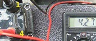
8. Using an ohmmeter, we measure the electrical resistance between the central terminal 15 and the housing (bracket). The device should show that there is no short circuit of the primary winding of the coil to ground. We sequentially measure the electrical resistance between the central terminal 15 and the outer terminals 1a and 1b. The resistance of each of the primary windings of the coil should be about 0.5 ohms.
Comment.
When measuring small values of electrical resistance (about 1 ohm), it is necessary to take into account the internal resistance of the device, which can be determined by shorting the ohmmeter probes.
9. Using an ohmmeter, measure the resistance between the high-voltage terminals of the coil 1 and 4, and then 2 and 3. The resistance of the windings should be about 5.4 kOhm.
A faulty ignition coil must be replaced.
5mm hex wrench
unscrew the four screws securing the coil to the bracket and remove the coil.
Comment.
10 mm socket wrench
with a deep head, unscrew the 3 screws securing it
11. Install the ignition coil (module) in the reverse order. We connect high-voltage wires in accordance with the cylinder numbers marked on each wire and on the coil (module) body next to the terminals.
Advice.
Since the numbering of the terminals on the coil (module) installed on the engine is not visible, it is better to connect high-voltage wires to the terminals of the ignition coil (module) before installing it on the engine.
Often, when the ignition module breaks down, the car owner immediately runs to the store and buys a new one. But, for the VAZ-2112 there is an alternative method - repair. Of course, without proper knowledge in auto electrics it will be difficult. This article will tell you in the most accessible way how to repair the ignition module with your own hands.
Ignition module
Before you begin repairing the ignition module, it is worth understanding what it consists of.
So, let's look at the design of this element:
- Two ignition coils that generate a high-voltage pulse.
- Dual channel switch.
If there are problems with the operation of the ignition module, there are reasons for this. It is worth warning that in the event of a malfunction, the “Check Engine” warning light will not light up: engine stops, loss of spark, interruptions in the operation of the power unit, etc.
For diagnostics and repairs, basic knowledge is required not only in conventional electrics, but also in the principles of auto electrics. Also, for a successful process you will need skills in working with a digital multimeter.
Repair process
Often, the high-voltage pulse disappears in cylinders 2 and 3
. So, to begin repairing the ignition module, of course, you will need to dismantle it. To do this, disconnect the high-voltage wires and unscrew the assembly itself from the fastenings. When the preparatory operations are completed, you can proceed directly to the repair process:
- We tear off the aluminum plate.
Use a screwdriver to open the aluminum plate - The internal world of the ignition module is quite rich and complex, at first glance, but everything is much simpler.
After opening, you can see the printed circuit board in silicone. Remove this sealant. The aluminum wires that connect to the contacts of the connectors and coils are torn. Opening the lid - We disassemble the computer mouse, or rather, only its multi-core wires will be needed.
We also remove all connections from the board. Wire soldering diagram and arrangement of elements on the boards - The ignition module circuit includes two L497D1 switches and two BU931 type transistors, which are considered quite powerful.
We solder everything with a special aluminum flux. Diagram of the assembled ignition module - First you need to solder the wires directly to the board. But soldering the wiring to the transistor collectors is much more difficult, since they are coated with special metal during manufacturing. This material is quite difficult to solder. First, remove the top layer from the metal. Before soldering, so that the heat does not dissipate, you need to place the plate on the stove and heat it to 180 degrees Celsius.
- Now, solder the wires to the contact module. The wire should be as short as possible.
- To insulate the contact soldering area, we coat it with varnish. You can use the one for nails.
- We check the finished product for functionality.
Completely assembled ignition module
Video about repairing the ignition module on a VAZ-2112
The video material will tell you about repairing the ignition module, as well as how to remove it from the car.
Possible malfunctions: signs and causes
Signs of a short circuit failure:
- when the driver presses the gas pedal, dips are felt;
- the power of the power unit decreases;
- the engine began to operate unstably at idle;
- the motor is shaking.
The main reasons why this can happen:
- Poor power supply in the car's electrical system. For normal operation of electrical components, a voltage in the on-board network of 11.5 volts is required. If the ignition wire is damaged or the battery performance is low, this may cause poor power supply. Accordingly, it will take more time to charge the short circuit.
- Mechanical damage to the device, for example, damage to the insulation. This problem may be caused by engine fluid entering the device through defective seals.
- Poor contact. Damage to the device, as well as constant exposure to moisture, can lead to failure of the primary and secondary windings, which in turn will contribute to the appearance of transition resistance. Such a malfunction can occur as a result of breakdowns in the washer system, washing the power unit, as well as heavy rain. Also, the structure of the device can be negatively affected by the salt that is sprinkled on roads in icy conditions.
- Thermal problems. Individual short circuits are more susceptible to high heat generation than others, which can also negatively affect the service life of the device.
- Working in vibration conditions. Due to high vibrations in engine operation, damage to the short-circuit structure may occur (video author - Resta channel).
Malfunctions of ignition modules on VAZ-2112
If the VAZ 2112 engine starts running intermittently or does not start at all, the cause of the problem may be the ignition module.
Characteristic symptoms of a malfunction of the ignition module of the VAZ 2110:
- insufficient engine power,
- when accelerating the car jerks,
- either 1 and 4 or 2 and 3 do not work at the same time,
- the engine does not start.
It should be noted that on the VAZ-2112 one of the coils is responsible for the operation of cylinders 1 and 4, the second - for cylinders 2 and 3. If one ignition coil fails inside the monolithic block, two cylinders stop working at once.
To eliminate all other components of the ignition system, make sure that the spark plugs are in working order.
Installation of a new ignition module for VAZ 2112
To do this, unscrew them and check the spark on each of the spark plugs by cranking the engine with the starter and placing the spark plug with the high-voltage wire on the head so that the body (threaded part) of the spark plug touches the engine mass.
If there is no spark or it is weak, replace the spark plug with one that is known to work. If this does not lead to anything, check the high-voltage wires.
Thus, we will exclude spark plugs, caps and high-voltage wires from the list of non-working elements. Next we will check the ignition module.
Design
Disassembled module
Structurally, the ignition module includes two main elements:
- 2 ignition coils that generate high-voltage pulses directed to the spark plugs;
- Dual channel switch.
The reasons for failure can be different, ranging from interruptions in the operation of the engine, ending with an unexpected stop of the power unit. Please note that the "Check Engine" light does not turn on.
Typical module failures
If you have at least a little knowledge of electronics, as well as a multimeter, you can independently diagnose and identify the problem. Checking the VAZ-2110 ignition module will take a little time, but will save you from purchasing an expensive unit
Please note that sometimes races appear that disappear over time
Errors will remain in the microcontroller, so they can be read using special testers. But as practice shows, at a time when the faults do not manifest themselves, the tester cannot recognize error codes that were previously present but then disappeared. Very often, the cause of failures is dirt on the contacts, poor fastening of the case, lack of mass, and the presence of electrical interference.
How to restore
Opening the aluminum plate, you will find a small printed circuit board on which the active components are located. It is coated with transparent silicone. It will need to be removed as it will interfere with repairs. Pay attention to the wires that connect the board and connector pins. They are aluminum, and this metal undergoes destruction much faster than copper. All these wires will need to be replaced. Some motorists who repair modules use wires that are used in mice for personal computers. But you need to get used to working with them - they are covered with paint.
In general, the diagram of the entire module is simple, it contains:
1. Two BU931 transistors (you can use the domestic analogue of KT848A, it performs well and is much cheaper).
2. Two SGS-THOMSON switches (model L497D1).