We continue to do a major overhaul of the six engine. Spare parts have been purchased, the block and crankshaft have been bored out. It seems like a trifle, just take it and assemble the engine yourself at home, saving money on the mechanic.
But, I had to remake a lot of engines after homemade ones, and stupid motorists.
Therefore, in this article I will try to explain how to properly assemble the engine, taking into account all sorts of little things, since without taking these little things into account, the engine will not work for a long time.
I start assembling the engine by installing the crankshaft, here there are a lot of little things that need to be taken into account.
When assembling the engine, you can wash it well, or you don’t have to, but the main thing is that everything inside the engine is clean, but I got greedy and basically don’t wash the outside of the engine, and everyone knows that. My only advice is that after repairing the engine, go to a car wash and wash the engine from above, if you wish.
On the other hand, I like the moment when the owner comes to pick up the car after repairs, opens the hood and sees a grimy engine, makes a face, but after starting it, breaks into a satisfied smile.
Before installing the crankshaft, you need to install the main bearings in the engine block bed; be sure to wipe the bearing beds clean with a rag before installing the bearings. So that there is not a single speck between the liner and the bed. The photo shows how to correctly install the inserts in the engine block.
Photo. Correct installation of liners in the VAZ engine block.
After installing the liners, be sure to lubricate them with oil.
Photo. Installed thrust half-rings (crescents)
And just before installing the crankshaft, install thrust half-rings (half-moons) into the block so that they do not fall and lubricate them with oil. Carefully place the crankshaft on the bearings and make sure that the crescents do not fall off.
I usually install crescents with brass plating, but if you have one crescent with brass plating and the other with aluminum, then install it with brass plating on the flywheel side.
Photo. Checking the longitudinal stroke of the crankshaft.
After installing the crankshaft, be sure to check the longitudinal stroke of the crankshaft. Usually I ensure that the longitudinal stroke of the crankshaft is zero, or a maximum of one tenth of a millimeter. You can check the longitudinal stroke of the crankshaft by inserting a screwdriver between the crankshaft cheeks from different sides. If you do not take into account the longitudinal stroke of the crankshaft, and the stroke is large, then the crescents will fall out, the crankshaft will dangle longitudinally in the engine, when you press the clutch, it will rest against the engine block and gnaw the metal in the block. Since I have been doing repairs for a long time, I have a whole bunch of working and new crescents; they also sell special repair crescents, they are thicker than standard ones. Therefore, it is easy for me to select crescents so that there is no longitudinal movement of the crankshaft. If, after installing standard crescents, there is longitudinal movement in the crankshaft, buy repair crescents, but it often happens that the crankshaft does not fit on the repair crescents, then try placing one working crescent and the other a repair one, or carefully grind off the excess metal from the repair crescent on a grindstone.
Photo. Checking the crankshaft for tightness.
After the crescents are selected, insert the liners into the cushions and attach them to the crankshaft, but do not tighten them too much right away, insert the key onto the crankshaft and start tightening one cushion at a time, and after tightening the next cushion, try to rotate the crankshaft. Details of checking and adjusting the liners can be found on the Crankshaft Repair page.
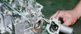
Photo. The connecting rod and piston are prepared for knocking out the pin.
Engine assembly
The washed and cleaned cylinder block is installed on the stand and the missing studs are wrapped.
Lubricate the cylinders, pistons, oil seals, bearing shells and thrust half-rings of the crankshaft with engine oil. Inserts without a groove on the inner surface are placed in the seat of the middle main bearing and in its cover, and liners with a groove are placed in the remaining seats and in the corresponding covers. The crankshaft is placed in the main bearings and two thrust half-rings are inserted into the rear support sockets with the recesses facing the thrust surfaces of the crankshaft; Moreover, a steel-aluminum half-ring is placed on the front side of the rear support, and a metal-ceramic half-ring (yellow) is placed on the rear side. On engines produced before 1980, a cermet half-ring must also be installed.
Install the main bearing caps in accordance with the marks. Then check the axial clearance of the crankshaft (the gap between the thrust half-rings and the thrust surfaces of the crankshaft). To do this, install indicator 1, as shown in the figure, and move shaft 2 with screwdrivers, checking the axial clearance using the indicator, which should be in the range of 0.06-0.26 mm. If the gap exceeds 0.26 mm, the thrust half-rings are replaced with others, new ones of normal size or repair ones, increased by 0.127 mm.
Place the rear oil seal holder gasket onto the crankshaft flange, and install the bolts securing the front clutch housing cover into the holder sockets. Place the holder with the oil seal on the mandrel 41.7853.4011 and, moving it from the mandrel to the crankshaft flange, attach it to the cylinder block. Install the front cover 6 of the clutch housing using two centering bushings.
Install the flywheel on the crankshaft so that mark B is opposite the axis of the connecting rod journal of the fourth cylinder.
After this, the flywheel is blocked with clamp A.60330/R and secured to the crankshaft flange.
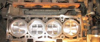
Using the bushing from set A.60604 for engines 2101 and 2103, or 02.7854.9500 for engines 21011 and 2106, or using the adjustable bushing 67.7854.9517, pistons with connecting rods are inserted into the cylinders. The “P” mark on the pistons should face toward the front of the engine. Sets of bushings for crimping piston rings during installation of pistons into cylinders include four bushings - one for nominal size pistons and three for oversized (repair) pistons. Therefore, it is necessary to select a bushing suitable for the size of the piston being installed.
Install the liners into the connecting rods and connecting rod caps, connect the connecting rods to the crankshaft journals and tighten the connecting rod bolts. The caps are installed so that the cylinder number on the cap is opposite the cylinder number on the lower head of the connecting rod.
Place the sprocket and oil pump drive shaft on the crankshaft and secure it with a thrust flange.
The gasket and cylinder head assembly with the intake pipe, exhaust manifold and valve mechanism are installed using two centering bushings on the block. Tighten the cylinder head bolts in two steps, as indicated in Section. "Removing and installing the cylinder head."
Loosen the nuts of the valve adjustment bolts and tighten the adjustment bolts deeper so that the valve arms lower and do not interfere with the installation of the bearing housing with the camshaft.
Rotate the flywheel so that the mark on the crankshaft sprocket coincides with the mark on the cylinder block. Place the sprocket (preliminarily) on the camshaft assembled with the bearing housing and turn it so that the mark on the sprocket is opposite the mark on the bearing housing. Then remove the sprocket and, without disturbing the position of the camshaft, install the bearing housing on the cylinder head and secure it by tightening the nuts in a certain sequence. After this, a chain guide is installed on the cylinder head.
Install the camshaft drive chain in the following sequence:
- lubricate the chain with engine oil, put it on the camshaft sprocket and insert it into the drive cavity from above, positioning the sprocket so that the mark on it coincides with the mark on the bearing housing. Then install the lock washer and the sprocket mounting bolt, without tightening it all the way;
- put a sprocket, a lock washer, and a bolt on the oil pump drive shaft without completely tightening it;
- put the chain on the crankshaft sprocket and install the chain tensioner shoe and tensioner without tightening the cap nut so that the tensioner spring can press the shoe; wrap the chain limiting pin into the cylinder block;
- turn the crankshaft two turns in the direction of rotation, which will ensure the necessary chain tension, and check that the marks on the sprockets match the marks on the cylinder block and on the bearing housing. If the marks match, then, having blocked the flywheel with lock A.60330/R, finally tighten the sprocket bolts, the cap nut of the chain tensioner and bend the lock washers of the sprocket bolts. If the marks do not match, then repeat the operation of installing the chain.
Adjust the gap between the camshaft cams and the valve drive levers. Install the camshaft drive cover with gasket and oil seal on the cylinder block without completely tightening the fastening bolts and nuts. Using mandrel 41.7853.4010, center the position of the cover relative to the end of the crankshaft and finally tighten the nuts and bolts of its fastening. Install the crankshaft pulley and tighten the ratchet.
Lubricate the oil filter O-ring with oil and install the filter by manually screwing it to the fitting on the cylinder block. Install the crankcase ventilation oil separator, the breather cap and secure the oil separator drain pipe clamp. Install the oil pump and oil sump with gasket.
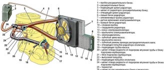
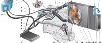
Install the coolant pump, generator bracket and generator. Place the belt on the pulleys and adjust its tension. The heater radiator inlet pipe and the outlet pipe are mounted on the cylinder head. Attach the heater radiator outlet pipe to the coolant pump and exhaust manifold. Install the sensors of the control devices, the drive gear of the oil pump and the ignition distributor.
They install the ignition distributor, for which:
- remove the cover from it, check and, if necessary, adjust the gap between the contacts of the breaker;
- turn the crankshaft until the compression stroke begins in the 1st cylinder, and then, continuing to turn the crankshaft, align mark 4 with mark 2;
- turn the rotor to a position in which its outer contact will be directed towards the contact of the 1st cylinder on the ignition distributor cover, and, holding the distributor shaft from turning, insert it into the socket on the cylinder block so that the center line passing through the spring latches , was approximately parallel to the engine centerline.
Secure the distributor to the cylinder block, install the cover and connect the wires. Screw the spark plugs into the cylinder head, install the key 67.78J2.9515 on them and tighten with a torque handle.
The fuel pump is mounted according to the instructions in section “Removing and installing the engine and its components.” They install a heat-insulating shield with gaskets, a carburetor and attach hoses to it. The carburetor is closed with a technological plug. Install the cylinder head cover with gasket and fuel line bracket. Pour oil into the neck on the cylinder head cover.
Top of page
The procedure for assembling a VAZ 2103 engine
Actions in emergency situations Daily checks Operating instructions Warnings and technical rules Basic instruments, measuring Engine and its systems Transmission Chassis Steering Brake system Vehicle electrical equipment Body Gas equipment Lighting devices Electrical circuits
In 1972, the Volzhsky Automobile Plant launched a new Zhiguli model - a complete analogue of the Italian sedan FIAT 124 Speciale of 1968, the design of which was redesigned in the same way as the base FIAT 124 turned into the VAZ-2101. The car was named, according to the classification accepted in the country, BA3-2103. The development of production of the model was provided for by an agreement with the FIAT concern somewhat later than the release of the prototype model, and the power unit was a 1.5-liter 2103 engine with a power of 73 hp. With. Naturally, for the vast majority of the country's population, the new car seemed completely new, more comfortable and prestigious, compared to the already produced VAZ-2101. In the same year, production of the VAZ 21035 model began - completely identical to the BA3-2103, but with a more economical VAZ-2101 engine with a power of 64 hp. With. Production of the BA3-21033 with a 1.3-liter VAZ-21011 engine (70 hp) began in 1977. The interior of the BA3-2103 was significantly different from the interior of the “kopek”. Due to the different design of the seats, it was possible to increase the space above the head, compared to the VAZ-2101, by 15 mm, and the distance from the ceiling to the seat is 860 mm. The instrument panel with a clock and tachometer and the interior upholstery, different from the previous Zhiguli, looked quite rich for the early 1970s, and the subsequent VAZ-2106 looked even more advantageous. The interior of the BA3-2103 was never modernized until the end of production (1984). The build quality in those days deserved respect: the size of the gaps in the body panels and the fit of the doors did not cause any complaints. Before the appearance of the more prestigious VAZ-2106 on the market and for some time after that, the BA3-2103 was deservedly considered the most comfortable and dynamic. Its popularity in the late 1970s was even greater than the recently appeared “Six” and “Niva”, which were considered unreasonably “complicated” and expensive. In 1976, the Tolyatti plant began production of the VAZ2106 model, which, in essence, was a modernized BA3-2103 with better dynamic qualities, comfort, interior and exterior body design. Then no one could have imagined that this particular model would become the most popular and mass-produced product of the Volga Automobile Plant. Unlike the BA3-2103, the VAZ-2106 is equipped with a more powerful 80-horsepower VAZ-2106 engine with a displacement of 1.6 liters, providing a maximum speed of 150 km/h and decent dynamics for that time - 16 seconds to 100 km/h. The front twin headlights received plas, the radiator lining changed, other bumpers with plas and “corners” appeared, the rear lights were combined with license plate lighting. The interior of the “six” looked even more advantageous than in the BA3-2103, and in comparison with Moskvich cars, these five-seater sedans were generally the height of comfort and prestige for wide sections of USSR motorists. Embossed seats with headrests, an instrument panel with a tachometer, excellent sound insulation and build quality are the components that, even after 30 years, serve as a strong argument when choosing this car. In 1979, the plant launched the production of less powerful modifications of the VAZ-21061 with a 1.5-liter 73-horsepower engine BA3-2103 and BA3-21063 with a 1.3-liter 64-horsepower VAZ-21011 engine. These modifications were not particularly popular among the people, but in conditions of Soviet shortages, the consumer had to put up with the combination of an expensive and heavy body with a weak engine, which noticeably worsened the dynamics, so the scale of production of the models was constantly increasing. In 1977, due to changing technology, the electrics on the BA3-2103 and VAZ-2106 changed: new terminals and wiring connections began to be installed. Since 1986, they began to install a new relay. Over the years of production, the carburetor has undergone several modernizations. The first was in 1974, when its design was only slightly revised, and in 1976 a quality screw was added. In 1980, they began to install an Ozone carburetor, model 2107. In 1982, another modernization was carried out. The VAZ-2106 began to be equipped with slightly modified 75-horsepower (according to the new GOST) VAZ-2106 engines. Reflectors were no longer installed on the rear wing along the molding line. In 1988, the exhaust system was modernized: it was equipped with a disposable gasket and nut. Since 1985, first on export modifications, and then sometimes on models for the domestic market, they began to install a 5-speed gearbox of the VAZ-2112 type, and later of the VAZ21074 type, which significantly reduces fuel consumption on the highway and engine noise. In 1990, VAZ introduced a kind of luxury package - VAZ21065, with a standard VAZ2106 engine with a contactless ignition system, a Solex carburetor (21053-1107010-03), halogen headlights, improved upholstery and other seat headrests. In addition, the modification was distinguished by bumpers from the VAZ-2105, electric heated rear window, a more powerful generator and a five-speed gearbox. Export modifications of the VAZ-21064 externally differed from the VAZ-21065 in bumpers with built-in direction indicators and a slightly different electrical circuit. This manual provides instructions for the operation and repair of all modifications of the BA3-2103 and VAZ-2106 produced since 1972.
Specifications
| Manufacturer | Autoconcern "AvtoVAZ" |
| Start year of release | 1972 |
| Volume, cm³ | 1452 |
| Power, l. With | 71 |
| Torque, Nm | 104 |
| Compression ratio | 8.5 |
| Cylinder block | cast iron |
| Number of cylinders | 4 |
| cylinder head | aluminum |
| Fuel injection order | 1-3-4-2 |
| Cylinder diameter, mm | 76 |
| Piston stroke, mm | 80 |
| Number of valves per cylinder | 2 |
| Timing drive | chain |
| Turbocharging | No |
| Hydraulic compensators | No |
| Valve timing regulator | No |
| Lubrication system capacity, l | 3.75 |
| Oil used | 5W-30, 5W-40, 15W-40 |
| Oil consumption (calculated), l/1000 km | 0.7 |
| Fuel supply system | carburetor |
| Fuel | gasoline AI-93 |
| Environmental standards | Euro 2 |
| Resource, thousand km | 125 |
| Weight, kg | 120.7 |
| Location | longitudinal |
| Tuning (potential), l. With | 200* |
*without loss of resource 80 l. With
Engine assembly VAZ 2101 to 2107
We continue to do a major overhaul of the six engine. Spare parts have been purchased, the block and crankshaft have been bored out. It seems like a trifle, just take it and assemble the engine yourself at home, saving money on the mechanic.
But, I had to remake a lot of engines after homemade ones, and stupid motorists.
Therefore, in this article I will try to explain how to properly assemble the engine, taking into account all sorts of little things, since without taking these little things into account, the engine will not work for a long time.
I start assembling the engine by installing the crankshaft, here there are a lot of little things that need to be taken into account.
When assembling the engine, you can wash it well, or you don’t have to, but the main thing is that everything inside the engine is clean, but I got greedy and basically don’t wash the outside of the engine, and everyone knows that. My only advice is that after repairing the engine, go to a car wash and wash the engine from above, if you wish.
On the other hand, I like the moment when the owner comes to pick up the car after repairs, opens the hood and sees a grimy engine, makes a face, but after starting it, breaks into a satisfied smile.
Before installing the crankshaft, you need to install the main bearings in the engine block bed; be sure to wipe the bearing beds clean with a rag before installing the bearings. So that there is not a single speck between the liner and the bed. The photo shows how to correctly install the inserts in the engine block.
Photo. Correct installation of liners in the VAZ engine block.
After installing the liners, be sure to lubricate them with oil.
Photo. Installed thrust half-rings (crescents)
And just before installing the crankshaft, install thrust half-rings (half-moons) into the block so that they do not fall and lubricate them with oil. Carefully place the crankshaft on the bearings and make sure that the crescents do not fall off.
I usually install crescents with brass plating, but if you have one crescent with brass plating and the other with aluminum, then install it with brass plating on the flywheel side.
Photo. Checking the longitudinal stroke of the crankshaft.
After installing the crankshaft, be sure to check the longitudinal stroke of the crankshaft. Usually I ensure that the longitudinal stroke of the crankshaft is zero, or a maximum of one tenth of a millimeter. You can check the longitudinal stroke of the crankshaft by inserting a screwdriver between the crankshaft cheeks from different sides. If you do not take into account the longitudinal stroke of the crankshaft, and the stroke is large, then the crescents will fall out, the crankshaft will dangle longitudinally in the engine, when you press the clutch, it will rest against the engine block and gnaw the metal in the block. Since I have been doing repairs for a long time, I have a whole bunch of working and new crescents; they also sell special repair crescents, they are thicker than standard ones. Therefore, it is easy for me to select crescents so that there is no longitudinal movement of the crankshaft. If, after installing standard crescents, there is longitudinal movement in the crankshaft, buy repair crescents, but it often happens that the crankshaft does not fit on the repair crescents, then try placing one working crescent and the other a repair one, or carefully grind off the excess metal from the repair crescent on a grindstone.
Photo. Checking the crankshaft for tightness.
After the crescents are selected, insert the liners into the cushions and attach them to the crankshaft, but do not tighten them too much right away, insert the key onto the crankshaft and start tightening one cushion at a time, and after tightening the next cushion, try to rotate the crankshaft. Details of checking and adjusting the liners can be found on the Crankshaft Repair page.
Photo. The connecting rod and piston are prepared for knocking out the pin.
Cold method of pressing a finger into a VAZ connecting rod. Video
The crankshaft has been installed, now we need to knock out the old pistons and install new repair pistons on the connecting rods. It is good to knock out the piston pins on a stump; drill a hole in the stump in advance, or knock it out with a chisel; the piston pin will be knocked out into this hole. It is advisable to knock out the finger with a special beard, or a round piece preferably with a diameter of 21 mm, and a heavy hammer. The piston pins are knocked out when cold; there is no need to heat them up.
Photo. Preparing pistons for installation on connecting rods.
Now we need to install new pistons on the connecting rods, you can install the pistons as is without modification, but I advise you not to be lazy and modify the pistons. First, chamfer the skirt using a sharpener or a file as shown in the photo, second, drill a hole in the piston skirt on both sides as shown in the photo.
Engines with modified pistons are much faster and more economical, since oil flows through the hole between the piston and cylinder skirt and reduces friction. Also, modified pistons do not suffer much if the engine accidentally overheats. The hole in the piston skirt used to be drilled 6mm, now it’s 14mm, so with a 14mm hole the engine turns out even faster.
Photo. A piston with a connecting rod, arrow 1 shows the front of the piston (letter P), arrow 2 shows the liner locks.
The photo shows how the piston should be positioned correctly on the connecting rod. You can drive your finger into the connecting rod while it’s hot, but here you don’t need to heat the connecting rod too much; it’s enough to heat it even in water to boiling water. Also, when the connecting rod is heated, you need to hammer in the piston pin very quickly, since if you hesitate a little, the pin will immediately take over the heating of the connecting rod and will become difficult to clog. I hammer it on a cold one, also on a stump, but I put a piece of a wooden block under the piston in the area of the piston pin, lubricate the pin and the hole in the connecting rod with oil, and also hammer the pin into the connecting rod with a heavy hammer. After hammering in the finger, be sure to check so that the finger is positioned exactly in the center and does not come out of the piston under any circumstances.
Ignition installation
After the valve adjustment is completed, we begin to set the ignition. Oil may leak out from under the distributor; to prevent this from happening, sealant must be applied under the distributor. The ignition is set to the fourth cylinder, the crankshaft pulley must be placed on the first mark of the cover, the mark of the camshaft sprocket should be at the very top, in the fourth cylinder this is the compression stroke, insert the distributor into the engine so that the slider faces the fourth cylinder towards the wire exit. Now we turn the distributor clockwise, as soon as the contact opens, the distributor can be tightened, all ignition is set. Now all that remains is to connect the sensors, install the valve covers, as well as the choke cable, throttle levers, and fill in antifreeze.
Self-repair of VAZ-2103 engine
The VAZ-2103, which is still driving around the Russian expanses, is today at a fairly advanced age, by automotive standards. Accordingly, their owners are increasingly faced with the need for repairs, including the engine. According to the manufacturer’s recommendation, the resource of this engine is 125 thousand kilometers. In practice, the Troika’s power units were looked after much more, of course, subject to careful treatment, as well as competent and timely maintenance.
Repairing the VAZ-2103 engine is quite possible to do on your own
The design of this power unit is quite simple. Accordingly, many car enthusiasts can do all engine-related repairs themselves. This option helps to save a certain amount due to the absence of the need to pay for the work of the craftsmen. There are a number of signs that indicate the need for repairs. Among them are:
- increased fuel and oil consumption;
- smoky exhaust with a clear bluish tint;
- uneven operation of the engine in idle mode;
- the appearance of soot on candles;
- clearly decreased power and sluggish dynamics;
- tripling;
- “sneezing” of the carburetor;
- “shots” in the silencer;
- constant overheating.
The simplest type of engine repair is replacing consumables. In principle, these works can even be classified as maintenance. If you want the engine of your “troika” to serve for a long time, you should change spark plugs, filters, and oil in a timely manner. Every 10 thousand kilometers it is necessary to adjust the valves.
It makes no sense to describe all possible repair options. It would probably be more correct to talk about how the engine is disassembled. Immediately before this, you should remove the engine from the car and wash it thoroughly. Now you can proceed directly to disassembly. We remove the carburetor, having first disconnected the hoses and throttle linkage, then the distributor and fuel pump, coolant temperature sensor. Now you can unscrew the spark plugs. Next comes the turn of all the hoses and pipes of the cooling system.
This must be done carefully, unless, of course, you plan to change them. After this comes the pump and generator drive belt, after which these components themselves are dismantled.
The oil filter is unscrewed using a special tool. Many Soviet-era car enthusiasts have it in their garages. Therefore, if you don’t have one, ask your friends so as not to spend extra money on the purchase. After unscrewing the filter, you can remove the oil pressure sensor. The next stage is dismantling the crankcase ventilation breather and the entire assembly. Now remove the drain tube clamp and remove the oil separator.
The ratchet can also be unscrewed using a special wrench. Now we fix it from turning and remove the crankshaft pulley. After this, you can begin to dismantle the camshaft drive cover and cylinder head. Next you will need to sweat a little. First, remove the bolts holding the oil pump and camshaft sprockets. Next, remove the chain tensioner and shoe. All that remains is to unscrew the limiting pin and remove the sprockets. That's it - you can pull out the chain.
Now we proceed to dismantling the crankshaft. Here you first need to unscrew the nuts of the studs securing the bearing housing. After this, the latter are removed along with the crankshaft. Next, you need to unscrew the mounting bolts and remove the cylinder head along with the manifolds. From there we remove the oil pump drive shaft, having previously dismantled the thrust flange. Next, we arm ourselves with a special puller and remove the crankshaft sprocket. In order to remove the pistons and connecting rods, first unscrew the nuts of the corresponding bolts. One important point is worth emphasizing here. Experienced car enthusiasts advise to be sure to mark connecting rods, bearings (as well as their caps) and pistons. This is necessary so that when reassembling you do not mix up anything.
After this, you can unscrew the flywheel mounting bolts and remove the washer. Here, in principle, everything is simple. Next, we remove the flywheel itself, after which, using a puller, we pull out the gearbox input shaft bearing from its socket in the crankshaft. However, the last step can be done later. This, as they say, is at your discretion. Now all we have to do is remove the crankshaft oil seal holder, the main bearings (after unscrewing the corresponding bolts), and the crankshaft itself. That's all - engine disassembly is complete.
What parts need to be repaired?
The VAZ 2103 engine has many problems.
But it’s worth considering the most popular of them:
- The first thing that should alert you is a knocking sound from the hood during idle. This sound occurs when the valve clearances need to be adjusted. The adjustment is carried out with your own hands if there is a diagram of the position of the elements in the valve mechanism.
- The second problem is rapid wear of the crankshaft. If the part is at its limit, the breakdown may occur suddenly or you will hear a characteristic knock from the engine, slightly less noticeable than in the first case. Do-it-yourself repair consists of dismantling and replacing the crankshaft.
- Engine overheating may be caused by a faulty cooling system. It is worth checking the fan, pump and thermostat. Sometimes the cause of overheating can be gasoline with a high octane number.
- If smoke is coming from the engine side, check the piston rings and carburetor. Most likely, oil got into the combustion chamber due to burnouts. Valve seals fail less often, which may lead to the need to overhaul the VAZ engine.
In all of the above cases, you need to replace the parts with new ones and get rid of the old ones.
VAZ 2106, 2103 » Engine » Engine assembly
Place the washed and cleaned cylinder block on the stand and tighten the missing studs.
Place liners without a groove on the inner surface in the middle bearing seat and its cover, and liners with a groove in the remaining seats and corresponding covers.
Note. Lubricate the engine cylinders, as well as pistons and oil seals, bearing shells and thrust half-rings of the crankshaft with engine oil before installation.
Place the crankshaft in the main bearings and insert two thrust half-rings into the sockets of the rear support (Fig. 1).
.Install the main bearing caps according to the marks (Fig. 2).
Place the oil seal holder gasket on the crankshaft flange, and insert the bolts securing the front clutch housing cover into the holder sockets (Fig. 3). Place the holder with the oil seal on the mandrel 41.7853.4011 and, moving it from the mandrel to the crankshaft flange, attach it to the cylinder block.
Install the front cover 6 of the clutch housing along the two centering bushings.
Install the flywheel on the crankshaft so that the mark (cone-shaped hole) near the rim is opposite the axis of the crankpin of the fourth cylinder, lock the flywheel with clamp A.60330/R and bolt it to the crankshaft flange.
Using the bushing from set 02.7854.9500, insert the pistons with connecting rods into the cylinders (Fig. 4). The set contains bushings of nominal and repair sizes of pistons. Therefore, it is necessary to select a sleeve suitable for the given size of the piston being installed.
Install the bearings into the connecting rods and connecting rod caps. Connect the connecting rods to the crankshaft journals, install the caps and tighten the connecting rod bolts.
Install the sprocket on the crankshaft. Install the oil pump drive shaft and secure with the thrust flange.
Install the cylinder head with the gasket, the exhaust manifold and the intake manifold onto the two centering bushings on the block. Tighten the fastening bolts in a certain sequence (Fig. 5) in two steps:
- preliminary torque 33.3 - 41.16 N m (3.4 - 4.2 kgf m) bolts 1 - 10;
- final torque 95.94 - 118.38 N m (9.79 - 12.08 kgf m) bolts 1 - 10 and torque 30.67 - 39.1 N m (3.13 - 3.99 kgf m) bolt eleven.
Turn the flywheel so that the mark on the crankshaft sprocket matches the mark on the cylinder block (Fig. 6).
Install the sprocket on the camshaft assembled with the bearing housing and turn the shaft so that the mark on the sprocket is opposite the mark on the bearing housing (see Fig. 8).
Remove the sprocket and, without changing the position of the shaft, install the bearing housing on the cylinder head and secure it by tightening the nuts in a certain sequence (Fig. 7).
Install the chain guide on the cylinder head. Install the camshaft drive chain: - put the chain on the camshaft sprocket and insert it into the drive cavity, installing the sprocket so that the mark on it coincides with the mark on the bearing housing (Fig. 9). Do not tighten the sprocket bolt all the way:
— install the sprocket on the oil pump drive shaft, also without completely tightening the mounting bolt;
— install the chain tensioner shoe and tensioner without tightening the cap nut so that the tensioner spring can press the shoe; wrap the chain limiting pin into the cylinder block;
— turn the crankshaft two turns in the direction of rotation to ensure the required chain tension; check that the marks on the sprockets match the marks on the cylinder block (Fig. 7) and on the bearing housing (Fig. 8);
— if the marks match, then lock the flywheel with lock A.60330/R (see Fig. 8), finally tighten the sprocket bolts, the chain tensioner cap nut and bend the lock washers of the sprocket bolts; if the marks do not match, repeat the operation to install the chain.
Adjust the gap between the camshaft cams and the valve levers.
Install the camshaft drive cover (Fig. 9) with a gasket and oil seal on the cylinder block without completely tightening the fastening bolts and nuts. Using mandrel 41.7853.4010, center the position of the cover relative to the end of the crankshaft and finally tighten the nuts and bolts of its fastening.
Adjustment of valves
You need to start adjusting the valves from the fourth cylinder, the mark on the camshaft sprocket should be opposite the camshaft mark, so we will adjust the 8th and 6th valves, then turn the crankshaft 180 degrees, then we can adjust the 4th and 7th valves, turn the crankshaft another 180 degrees 1 and 3, to adjust 5 and 4, turn another 180 degrees.
You can buy a feeler gauge designed for adjusting valves, this feeler gauge needs to be inserted between the camshaft and the rocker, loosen the nut by seventeen, and with a wrench of 13 you need to move the rocker so that it slightly clamps the feeler gauge. Now we slightly tighten the nut to seventeen, and with a wrench to 13 we loosen the rocker until the feeler gauge moves not hard but not easily, and now we tighten the nut to seventeen, if the feeler gauge tightens, the adjustment must be repeated. In my opinion, you don’t need to adjust the valves well right away, the point is that when you start the engine, it will run for a couple of minutes, the valves will clearly sit in their places, and you will have to adjust them again.