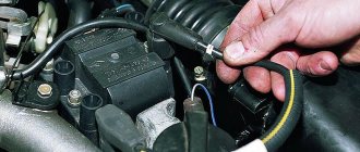
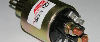
The VAZ 2107 ignition relay is used to turn on the power to the ignition system on carburetor and injection modifications of the “Seven”. Sometimes this part causes the machine to malfunction and has to be replaced. You can localize and fix the problem yourself, without resorting to the services of specialized service stations. This will require a minimum of tools and knowledge of where the relay is located and how to change it correctly.
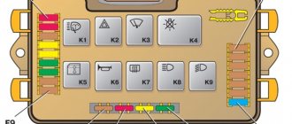
Main mounting block with fuses and relays
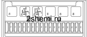
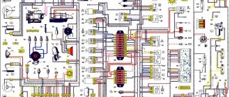
Diagram of the main mounting block of fuses and relays
Designations of fuses and relays of the mounting block
Open cover of the mounting block Location of the mounting block in the machine
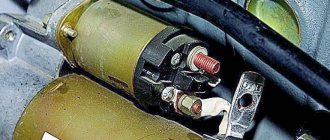
Relay
| Relay no. | vendor code | Purpose |
| K1 | lamp health monitoring relay | |
| K2 | windshield wiper relay | |
| K3 | relay-interrupter for direction indicators and hazard warning lights | |
| K4 | low beam headlight relay | |
| K5 | headlight high beam relay | |
| K6 | additional relay | |
| K7 | rear window heating relay | |
| K8 | backup relay (not installed on VAZ-2110 family vehicles) |
Circuit breakers
| No. prev. | Ampere | Purpose |
| F1 | 5 A | Lighting lamps: license plates, instruments, dimensions on the dashboard, left dimensions, trunk lighting |
| F2 | 7.5 A | Low beam in the left headlight |
| F3 | 10 A | High beam in the left headlight |
| F4 | 10 A | Right front fog lamp |
| F5 | 30 A | Door windows |
| F6 | 15 A | Portable lamp, cigarette lighter |
| F7 | 20 A | Radiator fan, horn |
| F8 | 20 A | Heated rear window |
| F9 | 20 A | Windshield washer and cleaner |
| F10 | 20 A | Reserve |
| F11 | 5 A | Dimension on the right side |
| F12 | 7.5 A | Low beam in the right headlight |
| F13 | 10 A | High beam in the right headlight |
| F14 | 10 A | Fog lamp, left |
| F15 | 20 A | Seat heating |
| F16 | 10 A | Hazard signal, turn signals |
| F17 | 7.5 A | Brake light, ignition switch illumination, interior lighting |
| F18 | 25 A | Cigarette lighter, glove compartment light, interior heater |
| F19 | 10 A | Reversing lamp, brake light monitoring |
| F20 | 7.5 A | Rear fog lights |
Rear fog light fuse
Additional fuse diagram
Location of the additional fuse in the mounting block
This is interesting: How should a pedestrian move along the side of the road?
How to check the serviceability/failure of the ignition switch of the “nine”?
The ignition switch, like any other element of the car, can fail. In such a situation, it is necessary to either repair the ignition switch or, in case of a serious malfunction, simply replace this element with a new one. However, in the latter case, before carrying out this very replacement, you should make sure that the ignition switch is actually faulty. How to do it?
The ignition key must be inserted into the ignition switch and this key must be installed in a certain position. During such actions, the circuit must be closed, which is used to judge the functionality of the lock. For example, when the ignition key is turned to the third position, the security system should begin to operate, and when the key is turned to the zero position, this system should turn off. Any deviations here will indicate actual problems with the ignition.
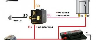
Relay and fuse box in the center console
Diagram of the relay and fuse box in the central instrument panel
Designation and numbering in the block
Location of the relay and fuse box in the console
Circuit breakers
| No. prev. | Ampere | Purpose |
| 1 | 15 A | ignition module, controller |
| 2 | 15 A | canister purge valve, vehicle speed sensor, oxygen sensor (heating) and air flow sensor |
| 3 | 15 A | fuel pump, injectors |
Relay
| Relay no. | vendor code | Purpose |
| 4 | electric fan | |
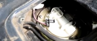
| 5 | electric fuel pump | |
| 6 | ignition |
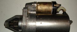
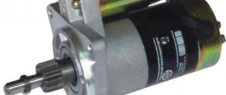
What does the VAZ 2109 ignition relay consist of?
When an electric current passes through the coil, an electromagnetic field is created there, and under its action the armature moves inside the core. When the power is turned off, the field disappears and the armature moves freely in the core. The VAZ 2109 ignition relay consists of an electromagnet, which is wound from an armature, a return spring, contacts and two windings.
The electromagnet consists of two coils: holding and retracting. The retractor is connected to the electric motor contact and the control terminal, and the retainer is connected to the relay body and the control terminal. When voltage is applied to the relay control contact, an electric current flows through the coils, creating an electromagnetic field there, and under its action the armature moves and compresses the return spring.
Relay box in the center console
Diagram of an additional relay block on the left side of the center console
Designation and numbering of relays and control units in the center console
Location of the relay box in the car
Designations
| Element no. | vendor code | Purpose |
| 1 | Central locking control unit | |
| 2 | Immobilizer block | |
| 3 | Rear fog lamp relay |
See also
Model range VAZ 2110
Is the mounting block with relays and fuses conveniently located?
| Rate the usefulness of the material: useful useless Thank you! Your vote has been counted! | Technical Department AG About the authors |
Additionally
| • All Vaz models with a galvanized body • What people ask about Vaz cars • Vaz dismantling shops in your city • Discuss the topic on the forum • See other instructions • on the forum: Auto repair and maintenance | Save this page! |
Possible malfunctions and ways to eliminate them
The nature of the lock assembly malfunctions on a VAZ 2109 car can also be electrical or mechanical.
The first group includes violations of the integrity of electrical circuits in the switch at a certain position of the key. If there is no contact, then the connected consumers may not work, or the car will not start at all. If there is contact, but the wrong parts of the circuit are closed, this is fraught with a short circuit and thermal damage to the lock. It will begin to melt and a characteristic smell will appear. Depending on the scale of the disaster, the contact group will most likely need to be replaced.
From a mechanical point of view, the core/larva may become stuck in some position. In this case, it will be physically impossible to turn the key in the lock. The only correct repair option is to replace the entire assembly.
To diagnose faults in electrical circuits, you need to stock up on the following tools.
- Multimeter or tester. If it is not available, as an option, you can use a control light operating at 12V voltage.
- A set of screwdrivers and keys for dismantling the lock. Since the only option for repairing mechanical faults is to replace parts that have failed, they will come in handy in this case as well.
Before starting diagnostics, you will have to disconnect the terminal block and ring all contacts in the sequence that corresponds to each of the key positions. For clarity, you should have an electrical diagram of the unit at hand. If the circuit is closed, there will be a resistance indication on the device.
Replacing the lock should begin with de-energizing it. To do this, you will have to loosen the fastening nut and remove the negative terminal of the battery. After this, the protective and decorative casing and the turn/window washer switches are removed. The lock is attached to the steering column using four screws or two screws and a hook latch. It may be difficult to remove due to the screws. In this case, they will have to be cut or drilled, doing everything extremely carefully. The terminal block is disconnected, and the dismantling process can be considered complete.
Assembling a new lock assembly occurs similarly, but in reverse order.
Lada 2000, 78 l. With. — electronics
Omsk
Lada 2111, 2001
49 000 ₽
Bratsk
Lada 2111, 1999
80 000 ₽
Rainbow
Lada 2111, 2001
60 000 ₽
Iskitim
Lada 2111, 2006
70 000 ₽
See more cars on Drome
Participate in the discussion can only registered users.
Login Register
Additional block
It is located under the center console and is covered with a lid. One part is accessible from the right side.
Scheme
Designation
- 15A - Ignition module, controller
- 15A - Canister purge valve, vehicle speed sensor, oxygen concentration sensor (heating), air flow sensor
- 15A - fuel pump, fuel pump fuse, injectors
- Electric fan relay
- Fuel pump relay
- Main relay (ignition relay)
The other part is on the left side of the console:
Scheme
Decoding
- Central locking control unit
- Immobilizer block
- Relay for turning on rear fog lights.
This is interesting: How to check the generator on a VAZ