The Hall sensor is the most important part of non-contact ignition and the slightest disturbance in its functioning leads to serious engine malfunctions. Therefore, it is important to be able to identify malfunctions by external features and know how to properly check the Hall sensor, and if necessary, install a new one. To do this, you need to understand the principles of operation and its features.
What is a Hall sensor and how does it work
The Hall sensor (also known as a camshaft position sensor) is one of the main elements of the distributor. It is located next to the distributor shaft, on which a magnetically conductive plate, similar to a crown, is attached. There are as many slots in the plate as there are cylinders in the engine. There is also a permanent magnet inside the sensor.
The principle of operation of the Hall sensor is as follows: when the shaft rotates, metal blades alternately pass through a slot in the sensor. As a result, a pulse voltage is generated, which enters the ignition coil through the switch and, converted into high voltage, is supplied to the spark plugs.
The Hall sensor has three terminals:
- one connects to the “mass”,
- the second is approached by a plus with a voltage of about 6 V,
- The converted pulse signal goes from the third terminal to the switch.
Hall effect
This was back in the 19th century. American physicist Edwin Hall discovered a very strange effect. He took a plate of gold and began to pass direct current through it. In the picture I marked this plate with faces ABCD.
He passed a direct current through faces D and B. Then he brought a permanent magnet perpendicular to the plate and discovered a voltage on faces A and C! This effect was named after this great scientist. The basic physical principle of this effect was based on the Lorentz force. Therefore, radioelements based on the Hall effect began to be called Hall sensors.
But there is one small nuance here. The fact is that the Hall voltage, even at the highest magnetic field strength, will be some microvolts. Agree, this is very little. Therefore, in addition to the plate itself, DC amplifiers, switching logic circuits, a voltage regulator, and a Schmitt trigger are installed in the Hall sensor. In the simplest switching Hall sensor it all looks something like this:
Where
Supply Voltage – sensor supply voltage
Ground - earth
Voltage Regulator - voltage regulator
A – operational amplifier
Hall Sensor – actually the Hall record itself
Output transisitor Switch - output switching transistor (transistor switch)
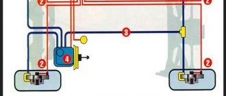
The role of the sensor in the SZ system
If the sensor or DC malfunctions, problems arise related to the direct functioning of the engine. The car may not start at all or behave extremely poorly on the road. Is it really possible for such a small element as DH to have such a powerful effect on a car’s engine? Yes, yes.
Hall sensor circuit
What is DH? This is a controller capable of sensitively responding to any changes in the magnetic field. If the DC is faulty, the injector stops functioning.
The interaction of the DC with the ignition system in the electrical sense is carried out through a switch or conductor. As a result, a magnetic field appears.
Theory
Once upon a time, mechanical interrupters (contacts) were used in battery ignition systems. At the right moment, they opened the circuit in the primary winding of the ignition coil - the current disappeared, the effect of magnetic induction occurred and a high voltage was induced in the secondary winding of the ignition coil, which was supplied to the spark plug. And then, in the form of a spark discharge, it jumped between the electrodes of the spark plug, forming a spark that is well known to all of you.
In modern ignition systems, such as CDI, which is what we will talk about, the principle of spark discharge formation remains almost the same. With the exception of the method of controlling the moment of sparking.
Types of Hall sensors
Hall effect sensors can be divided into two types:
- Based on the Conclusion
- Based on operation
Linear (analog) Hall sensors
In linear sensors, the Hall voltage (voltage on edges A and C) will depend on the magnetic field strength. Or in simple words, the closer we bring the magnet to the sensor, the greater the Hall voltage will be. This is a linear relationship.
In linear Hall sensors, the output voltage is taken directly from the operational amplifier. That is, in linear sensors you will not see a Schmitt trigger, nor an output switching transistor. That is, it will all look something like this:
What does the voltage on faces A and C depend on? Mainly from a magnetic field created by either a permanent magnet or an electromagnet; the thickness of the plate, as well as the strength of the current flowing through the plate itself.
Theoretically, if a very strong magnetic flux is applied to the Hall sensor, then the Hall voltage will be infinitely large? No matter how it is). The output voltage will be limited by the supply voltage. That is, the graph will look something like this:
As you can see, up to a certain point we have a linear dependence of the sensor output voltage on the magnetic flux density. Further increase in the magnetic flux is useless, since it has reached the saturation voltage, which is limited by the supply voltage of the Hall sensor itself.
Thanks to these parameters, using a Hall sensor, devices were built that made it possible to measure the current strength in a conductor without touching the wire itself, for example, current clamps.
There are also instruments that can be used to measure the magnetic field strength. Hall sensors used in these devices are called linear , since the voltage across the Hall sensor is directly proportional to the magnetic flux density.
This is interesting: How to replace the crosspiece on a VAZ-2105 yourself
Linear sensors, as I already said, can be used in current clamps. They allow you to measure current ranging from 250 mA to several thousand Amperes. The biggest advantage in such current clamps is the absence of mechanical contact with the measured circuit. In other words, Hall effect current meters are much safer than shunt and ammeter based meters, especially when the circuit current is high, which is often found in industrial installations.
Digital Hall sensors
As soon as the era of digital electronics began, various logic elements began to be placed in one housing along with a Hall sensor. We have already reviewed the simplest Hall sensor on a Schmitt trigger above and it looks like this:
In fact, such a sensor has only two output states. Either the signal is present (logical one) or it is not (logical zero). The hysteresis on the Schmitt trigger simply eliminates frequent switching, which is why it is always used in digital Hall sensors.
As a result, the industry began to produce Hall sensors for digital electronics. Basically, such sensors are divided into three types.
Unipolar Hall sensor
As the name suggests, these sensors only require the positive magnetic field of the magnet's south pole to activate as well as release the sensor.
Bipolar
We bring the magnet to one pole - the sensor will work and will continue to work even when we remove the magnet from the sensor. In order to turn it off, we need to apply a different magnet polarity to it.
Connecting large electrical loads
The output power of the Hall sensor is very low (10–20 mA), as a result of which it cannot directly control high electrical loads. The problem is solved quite simply: the connection is made by adding an NPN transistor to the device, through which current flows to the output. The specified part acts as a receiver; when it is saturated, it is activated as a switch. The transistor grounds the output contact, thus closing it when the flux density of the set values for “on” increases.
There are various configurations of the transistor switch, but the main thing is that the device provides a 2-cycle output, allowing it to draw the required current to control large loads.
Application of Hall sensors
Currently, the scope of application of Hall sensors is very extensive and is becoming wider and wider every year. Here are the main applications:
Application of linear sensors
- current sensors
- tachometers
- vibration sensors
- ferromagnetic detectors
- rotation angle sensors
- non-contact potentiometers
- brushless dc motors
- flow sensors
- position sensors
Application of digital sensors
- speed sensors
- synchronization devices
- car ignition system sensors
- position sensors
- pulse counters
- valve position sensors
- door lock
- flow meters
- contactless relays
- proximity detectors
- paper sensors (in printers)
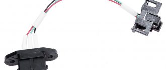
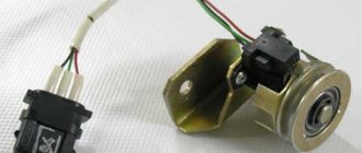
Basic information
Let's start with basic information: where is the Hall sensor located, what is it, what is it for. A “naked” sensor is a small meter (sensor, detector), almost always black (the color depends on the manufacturer’s preferences), several millimeters in size. Automotive products have a relatively large plastic protective box, a “chip” with a cable with a connection connector.
The phase sensor monitors magnetic fields and their parameters (strength), while producing specified operating algorithms (closing contacts, etc.).
The sensors in question were named after the scientist Hall, who discovered that a potential difference (Hall voltage) occurs when objects with direct currents are placed in a field.
The car current sensor is located in the distributor - a unit for connecting spark plugs; it is hidden by a plastic chip with three wires and a connector for them. On other devices it can be placed anywhere. Usually on printed circuit boards it is a tiny black box, usually with 3, less often - 4 legs. Linear Hall sensors resemble a microcircuit. The product is also identified by its markings; the designations are in reference books of radio components (common ones are S41, 41F, U18, 3144, 44E, 49E).
When current flows in one direction, electrons are deflected in conductors placed perpendicular to the field. Their areas have an uneven density of particles, this is the potential difference recorded by the Hall sensor. It becomes possible to analyze voltage at right angles to current.
There is also a simplified Hall effect sensor, as, for example, in smartphones: only with the function of confirming the presence of magnetic phenomena, the tension is not analyzed. Based on a unit that includes a sensor and a magnetometer, the phone is equipped with a compass option.
How it works
Operating principle of using a Hall sensor:
- When current passes, electrons move linearly through the sensor.
- When exposed to a field, particles with a charge are deflected by the Lorentz force along a curved path.
- Negatively charged elements, also known as electrons, are attracted to one side of the Hall sensor, and positive ones (holes) are attracted to the other.
- The described accumulation in different segments creates different voltages, this is the potential difference. The proportionality of the resulting voltage to the electric current and field strength is direct. These final phenomena are tracked by the sensor; the principle is used to determine the position of the objects being serviced under their control.
Where are they used?
Phase sensors began to be installed in structures about 75 years after their invention, when technologies for creating semiconductor film materials became available.
Typical areas of application of Hall sensors:
- the first area where use began was mechanical engineering, for measuring the angles of camshafts, crankshafts, and detecting sparks on ignition units;
- switches (non-contact type), analyzers for levels of substances, speed of rotation of blades, devices for remote detection of currents;
- scanning magnetic symbols;
- as a replacement for reed switches (circuit breakers with closing contacts via a magnet). In this area, the described devices are the most common due to the large number of devices: microelectronics, equipment from headphones to manipulators, keyboards, in elevators, security equipment (doors, locking elements).
On a smartphone
The hall sensor in a smartphone is used for the following purposes:
- as part of a compass, magnetometer;
- for monitoring the closing/opening of a case with a magnetic latch by tracking field weakening/increasing;
We will describe why a hall sensor is needed in a smartphone on the cover. When the magnet moves away from the detector, there is an impulse to activate the display, when closer, it turns it off. A variety of such cases is a separate type of product, usually called Smart Case. There are also additional functions, their operating principle is as follows: if a cover without windows near the display is used, then the detector turns off the screen when it is closed, and automatically activates when it is opened. If there are windows, switching of contents to the display is initiated. On the visible area there is a clock, etc., on the entire display there is all the information.
Not all smartphones have the described improvement, and manufacturers do not always indicate it in the list of options, so you need to clarify this parameter. But if in the recommended accessories there is a note about those suitable from the Smart Case category, then this option is present.
Why does the Hall sensor fail?
Damage to the sensor can manifest itself with different symptoms - even a professional can sometimes find it difficult to determine the exact cause. Here are the signs that indicate a sensor failure:
- the engine does not start well;
- idling with constant interruptions;
- at high speeds the car jerks;
- the spark on the candles disappears;
- the engine suddenly stalls.
The main reason for the failure of this part is trivial - dirt has accumulated. As soon as this happens, the DH signals immediately. “Miracles” begin to happen to the car. However, it is wrong to blame this device for all the troubles - a thorough check is needed.
A common cause of failure is a lack of contact in the wiring. In total, the device has 3 contacts - connecting it to ground, to plus, to the switch. One of the contacts could have oxidized, causing the electrical circuit to break.
Finally, the wire may simply break or break. This occurs due to the fact that the vacuum ignition corrector displaces the platform on which the DC is located, shifting the ignition angle. To avoid such a misfortune, the wiring must be secured so that it bends in a loop.
If the high-voltage wiring in the car is worn out and lies next to the sensor wires, a high-voltage breakdown is possible. Often breakdowns occur in wet weather, when the wheel drives into a deep puddle.
A breakdown may occur due to overcharging of the battery generator - when the DC experienced too much load and one of the parts burned out at the input of the switch.
Signs of a Hall sensor malfunction
Hall sensor malfunctions manifest themselves in different ways. Even an experienced technician will not always immediately identify the cause of engine problems.
Here are some of the most common symptoms:
- The engine starts poorly or does not start at all.
- At idle, the engine runs rough and jerky.
- The car may jerk when driving at high speeds.
- The power unit stalls while driving.
If one of these signs appears, you must first check the serviceability of the Hall sensor.
Also, do not exclude other malfunctions of the ignition system found in cars.
Basic sensor malfunctions
Any part on a car sooner or later begins to malfunction, and the Hall sensor is no exception, even though it has the simplest design. Its breakdown is detected by detecting the following defects:
- Inability to start the engine.
- Unstable and unstable operation of the motor.
- The occurrence of jerks.
- The engine begins to stall.
- The appearance of the detonation effect.
If the above symptoms appear, then there is no need to rush to change the Hall sensor, since similar phenomena can also occur due to other breakdowns of the ignition and fuel supply system. To verify that the device is faulty, you will need to perform a suitability test.
Repair
There is no point in repairing Hall sensors, since the cost of this will exceed its cost, which is in the range of $3–5.
If, out of curiosity, someone wants to do repairs, then you can try to do this for automotive products, but the repair will not concern the very core of the sensor, but the “chip” and the cable: the capacitor often burns out, it and the wires can be resoldered. The cause of the malfunction may lie in soured contacts; they are cleaned.
How to check the Hall sensor
A simple way to check the camshaft position (Hall) sensor is shown in the following video.
There are several ways to check the health of the Hall sensor. Each motorist can choose the most suitable option for himself:
- Take a working sensor from a neighbor or at a car disassembly for testing and install it instead of the “native” one. If the engine problems disappear, then you will have to buy a new part.
- Using a tester, you can measure the voltage at the sensor output. In a working device, the voltage will vary from 0.4 V to 11 V.
- You can create a simulation of a Hall sensor. To do this, remove the three-pin block from the distributor. Then turn on the ignition and connect outputs 3 and 6 of the switch with a piece of wire. The appearance of a spark indicates that the sensor has failed.
This is interesting: Setting up the light and independently adjusting the headlights on a Volkswagen Polo Sedan
If the test reveals that the Hall sensor is faulty, then it must be replaced with a new one.
Checking the sensor with a multimeter
You can check the DH in different ways. One popular diagnostic option is a multimeter or voltmeter. This verification method has two options. Let's look at how to check a car's hall sensor in both cases.
1st method
To carry out diagnostics, you need to find a working voltmeter or multimeter that is set to measure DC voltage (direct current) in the range of 20 Volts. In addition, you will need to stock up on 2 iron pins, through which the DC will be checked.
Before checking the hall sensor, you will need to remove the rubber boot from the block, which is connected to the distributor and directly to the DH.
- remove the main armored wire from the distributor;
- We connect it to the arrester or to ground.
This is done in order to exclude the accidental occurrence of a discharge, because this may contribute to starting the engine during the test.
- turn on the ignition;
- remove the block from the distributor;
- set the mode on the multimeter to DC 20 V;
- We connect the negative terminal of the device to ground (any part of the car body);
- the positive probe of the device will serve as a voltage meter.
The block going to the distributor has three wires: red, green and white (colors may be different). On the red wire, the voltage of the device should show 11.37 or close to 12 V. On the green or middle wire, the value is also close to 12 V. And finally, on the last - white wire, the value is 0.
By the way, if you put the device in the audio test mode, then placing the probe on the contact, you will hear a constant ringing, which will indicate that the white wire is connected to ground. That's how it should be.
What did the preliminary check give? We made sure that the households received all the necessary impulses.
Continue (multimeter in DC measurement mode):
- We take the prepared pins (studs) and thread them like this: one into the green (middle wire), the other into the white (ground wire);
- We connect the block in its place, in the car distributor.
Why are pins needed? They play the role of a current conductor. There are no contacts on the back of the block, and the values can only be checked if the wires are exposed. This is not recommended, which is why the pins are inserted.
- take the multimeter clamps (ignition is on);
- We connect the positive terminal of the multimeter to the pin of the middle wire of the block, and the negative terminal to the other (white wire).
In this position, the multimeter value should be within 11.2 V.
- crank the crankshaft while simultaneously observing the instrument readings;
- if the instrument readings drop to 0.02 V (lower measurement limit) and rise to 11.8 V (upper measurement limit) when cranking the crankshaft, then this is considered normal.
Attention. The DC is considered to be in good working order if, when cranking the crankshaft, the upper limit of measurement is no less than 9 V, and the lower limit is no more than 0.4 V.
Thanks to these measurements, we checked the performance of the DC installed in the car distributor.
2nd method
The second verification method differs from the first in that this time the DH is diagnosed autonomously. In other words, it will not be connected to the ignition system - to the switch.
So, to carry out this method you will need a homemade assembly of 3 contacts inserted into the distributor block, plus/minus pins and 2 test points for measurements. The homemade assembly diagram will look like this
Here's what to do:
- Connect the three homemade contacts to the connectors where the original distributor block is inserted (if the sensor is removed, then to its terminals);
- supply plus/minus power to the homemade assembly;
- connect the plus of the multimeter to one control point for measurement, the minus to the other;
- turn the crankshaft.
Again, the upper limit of measurement on a working sensor should not be lower than 9 V, and the lower limit should not be higher than 0.4 V.
If the DH is removed from the car, then it will be checked as follows:
- the sensor leads are connected to the homemade assembly (the other connections are the same as in the case described above);
- take a knife or curtain and draw the blade along the slot in the DH.
When the curtain is closed, the DC readings are above 9 V, and when the curtain is open, they are below 0.4 V.
Thus, using a multimeter, you can check the DC for serviceability in 2 simple ways. Of course, there are many other options for checking the sensor, but they are more difficult to carry out, although they provide instant access to the DH.
A general familiarity with the operating principle of DCs, despite the gradual displacement of contactless ignition systems by multiprocessor ones, will provide many benefits in the future. So, this can help the car owner when using other car sensors that operate on the Hall principle: speed sensor, camshaft position, etc.
This is interesting: What to do if the airbag light comes on?
Forget about fines from cameras! An absolutely legal new product - Traffic Police Camera Jammer, hides your license plates from the cameras that are installed in all cities. More details at the link.
- Absolutely legal (Article 12.2);
- Hides from photo and video recording;
- Suitable for all cars;
- Works through the cigarette lighter connector;
- Does not cause interference to radios and cell phones.
If you find an ERROR, please select a piece of text and press Ctrl+Enter (on Windows) Cmd+Enter (on Mac).
Jerking of the car, problems with starting the engine, interruptions in engine operation - these and other problems may indicate a breakdown of the Hall sensor.
other methods
If the symptoms of a Hall sensor malfunction do not convince you that it is the problem, you can try measuring the resistance on the sensor. Here you yourself will have to act as a designer and make a device whose constituent parts are:
We solder a resistance to one leg of the LED, and 2 wires to it. We choose the length of the wires ourselves - so that it is more convenient to work. We dismantle the distributor cover, disconnect the plug assembly and the distributor. Then we diagnose the electrical circuit. To do this, connect the voltmeter to terminals 1 and 3, and activate the car’s ignition. If the unit is working correctly, a value of 10-12 volts will appear on the screen.
Then we connect the device made for measurement to the same terminals. The LED will definitely light up if the polarity is selected correctly. If this does not happen, the wires must be swapped. Then we proceed like this:
- leave the wire connected to the first terminal alone;
- transfer the third terminal to the second;
- crank the camshaft (manually or using a starter).
The principle is simple: if the LED blinks when the shaft is turned, it means everything is working and the sensor is in order. Checking sensors on different car models is carried out according to the same scheme.
You can also ask your friends to borrow a device that is known to work. Contact car enthusiasts whose cars have identical sensors. If the problems disappear, this means that the DC on your car is faulty.
Hall sensor replacement
Replacing the Hall sensor will not be particularly difficult. Even a novice car enthusiast can handle this work with his own hands.
The video below shows in some detail the process of replacing the sensor in the distributor of a UAZ car.
Typically, replacing a Hall sensor consists of several steps:
- First of all, the distributor is removed from the car.
- Next, remove the distributor cover and align the timing mechanism mark with the crankshaft mark.
- Having remembered the position of the distributor, you need to unscrew the fasteners with a wrench.
- If there are latches and stoppers, they should also be removed.
- The shaft is pulled out of the distributor.
- All that remains is to disconnect the terminals of the Hall sensor and unscrew it.
- By pulling back the regulator, the faulty part is carefully removed through the gap formed.
- The new Hall sensor is installed in the reverse order.
Checking the functionality of the Hall sensor not only allows you to accurately determine the cause of engine failure. Thanks to simple techniques, the motorist will save his time on repairs and also eliminate unnecessary waste of money.
How to remove the sensor?
In order to perform the replacement, you need a “10” key and a screwdriver. This is quite enough, but it is still recommended to have pliers with you. So, you need to remove the distributor and disassemble it:
- Disconnect the ground wire from the battery.
- Disconnect all the armor wires and the vacuum corrector tube from the distributor. If in doubt, mark the location of the armor wires so as not to be confused.
- Unscrew the three nuts that secure the distributor housing to the engine head. Pay attention to the position in which the body was standing.
- Disconnect the wiring block and remove the distributor housing.
Now you need to disassemble it; to do this, remove the cover by unscrewing two bolts. Next, remove the slider and underneath it is the Hall sensor.
How to install a new one?
When replacing the Hall sensor on a VAZ-2109, you must follow a strict procedure. Distortions are not allowed, as this will lead to system inoperability. All wires are carefully laid inside the distributor housing so that moving elements do not damage them.
Remove the old sensor and put a new one in its place. Assemble the distributor in the reverse order - the dust cover should fit into the groove, then install the slider. By the way, it’s worth checking - the resistance is about 5 kOhm, there should be no carbon deposits or melting. If there is damage, the element must be replaced. If replacing the sensor does not help, you need to look for a problem in the injection system or switch or coil.
Self-check and problem solving
The only way for an inexperienced car enthusiast to check the Hall sensor is to contact a car service center. However, a vehicle owner who wants to solve the problem faster and cheaper can perform the diagnostics themselves. And then either correct its position or replace it with a workable version. Meanwhile, a temporary replacement allows you to determine the need for replacement - if the new sensor works, then it is the cause of the malfunction.
The part can be checked using a voltmeter connected to its input terminals. Indicators from 0.4 to 3.0 V are considered normal - a higher or lower value indicates the need for replacement. And, checking the Hall sensor using its simulator, connect the 3rd and 6th terminals of the switch with a wire. The appearance of a spark is evidence of failure of the part.
The device is replaced in several stages:
- Remove the distributor cap;
- Align the first mark on the crankshaft pulley with the middle line on the timing cover;
- Mark the position of the slider (for example, with a pencil) and turn the distributor mount with a key 13;
- Knock out the pin with which the oil deflector clutch is fixed;
- Remove the crankshaft and clutch, after which the DC terminals are disconnected;
- Pull back the regulator and remove the part.
Installation is performed in reverse order. And in order to always have the replacement sensor at hand, it is advisable to buy it in advance and carry it in the car. The cost of purchasing a new part will be offset by the time saved if you have to replace a worn out old one on the road.