The crankshaft position sensor is designed to synchronize the ignition system and the operation of fuel injectors in a gasoline injection engine. Accordingly, its breakdown will lead to the fact that the ignition will be in a hurry or delayed. This will lead to incomplete combustion of the fuel mixture, unstable engine operation or complete failure.
Currently, there are three types of sensors - induction, based on the Hall effect, and optical. However, the most common sensors are those of the first type (induction). Next, we will talk to you about possible malfunctions and methods for eliminating them.
Crankshaft sensor. Why is it needed and how does it work
The crankshaft sensor on an injection engine is needed to determine the angular position of the crankshaft, as well as to determine the moment when the first and last piston pass the top dead center (TDC).
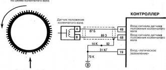
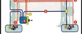
This sensor transmits these indicators to the electronic unit, which determines the crankshaft speed and, based on this, makes corrections in the ignition system and fuel supply system. Operating principle of the crankshaft position sensor. There may be more or less teeth depending on the engine
Most often, induction crankshaft sensors are used on cars. Its work is based on a change in the magnetic field that the device creates when some metal object passes through it. On engines this is implemented like this: a special metal toothed synchro disk is installed on the crankshaft; it is usually installed on the generator drive pulley. There is a gear ring around the circumference of this disk, but in one place two teeth in a row are missing. The crankshaft sensor is located opposite this disk at such a distance that the tops of the teeth fall into the magnetic field of the sensor. The crankshaft position signal is those two missing disc teeth. The part of the disk where there are no teeth passes through the magnetic field of the sensor, changing it. The sensor detects this change and transmits it to the control unit.
Where is the sensor located?
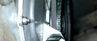
Location of the crankshaft position measuring device: next to the disk between the generator pulley and the flywheel. To freely connect it to the on-board network, a 50–70 cm long wire is provided, which has connectors for keys. There are adjusting shims on the seat to set the gap to 1-1.5 mm.
Why do you need a timing sensor?
DPKV records and transmits the following indicators to the ECU:
- the moment the pistons pass TDC and BDC in the first and last cylinders;
- crankshaft position measurement.
The received data is transmitted to the ECU. As a result of processing information about the position of the crankshaft in relation to the dead points and its rotation frequency, the synchronization sensor corrects the following indicators of the internal combustion engine:
- the volume of gasoline entering the cylinders;
- fuel supply time;
- ignition timing;
- camshaft rotation angle;
- moment and duration of operation of the adsorber valve.
The tasks of the electronic unit may vary depending on the complexity of the internal combustion engine device, but not a single ECU operates without a crankshaft position sensor.
As a result of a malfunction of the DPKV, sparking is either delayed or ahead of the engine's power stroke, which leads to improper operation of the internal combustion engine or to the engine not starting. This contributes to incomplete combustion of the working mixture and, as a result, excessive fuel consumption and a decrease in the dynamic performance of the car.
On which internal combustion engines is it installed?
Such a device cannot be mounted on cars without an on-board computer and on carburetor engines. Therefore, DPKV is present only on diesel engines and injection engines. To find out the location of the crankshaft sensor, you need to take into account the features of its operation:
- parts of the crank group, pulleys and flywheel are attached to the crankshaft;
- The crankshaft is hidden in a tray; belts of gears of the same name are put on the pulleys, so it is very difficult to attach the sensor near these parts;
- The flywheel is the largest part and relates to several engine systems at once, so the DPKV is connected near it to ensure quick access during replacement.
DPKV is installed only in internal combustion engines with electronic ignition
Attention: The crankshaft position sensor is considered a non-repairable electronic device. It is diagnosed and replaced when faults are identified entirely.
Purpose and principle of operation of the crankshaft position sensor
The crankshaft position sensor (CPS, synchronization sensor) is a component of the electronic engine management system.
Therefore, the sensor is only available in modern cars equipped with an electronic engine control unit (ECU). The function of the crankshaft position sensor is to transmit signals to the electronic engine control unit about the position of the crankshaft, as well as the speed and direction of its rotation. Thus, the sensor affects the functioning of the main engine systems, including ignition, gas distribution, power, etc. Based on the readings transmitted by the DPKV, the electronic control unit solves the following range of tasks:
- determines the moment of injection and the duration of operation of the injectors (control of the fuel injection system);
- controls the ignition timing in each of the engine cylinders (ignition system control);
- determines the moment when the pistons of the first or fourth cylinders pass the top and bottom dead centers;
- controls the valve timing system;
- controls the operation of individual components of the fuel vapor recovery system;
- monitors and adjusts the operation of other engine systems.
It is the DPKV that determines the correct functioning of the two main engine systems - ignition (only on gasoline engines) and fuel injection (on diesel and injection gasoline power units).
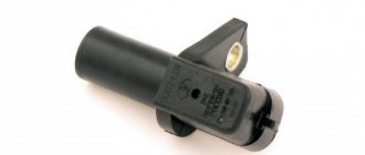
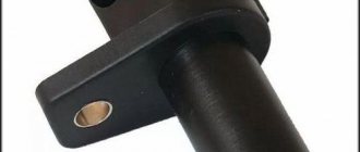
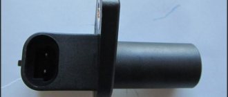
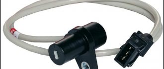
The sensor itself is a steel core with a copper wire winding, filled with a compound resin and placed in a plastic housing. A special feature of the sensor is the presence of a wire 50-70 centimeters long, ending with a special connector that connects to the engine control unit.
There are 3 main types of DPKV.
- A magnetic (inductive) sensor is the most common option and does not require separate power. A signal is generated to the electronic control unit at the moment when a special tag passes through the magnetic field created in the area where the sensor is located. At the same time, the magnetic sensor can serve as a speed sensor.
- Hall sensor, the operating principle of which is based on the Hall effect (the occurrence of a transverse potential difference). The signal to the ECU is received from the DPKV at the moment when a changing magnetic field approaches the sensor. The synchronizing disk blocks the field, and the teeth of the disk interact with the magnetic field of the DPKV. A sensor of this type can simultaneously serve as an ignition distributor sensor.
- An optical sensor whose operating principle is based on interaction with the synchronization disk by blocking the optical flow passing between the LED and a special receiver. The receiver detects the overlap of the light flux and generates a voltage pulse, which is transmitted from the DPKV to the electronic engine control unit.
Most often, magnetic meters and Hall sensors are found on cars - the versatility of these devices makes them more popular than optical crankshaft position meters, which are an outdated solution.
Functions of the sensor and the threat of its breakdown
The purpose of the crankshaft position sensor (CPS) is to synchronize the supply of gasoline and engine start. The device sends a signal to the electronic control unit, which, in turn, regulates the operation of these systems. The working principle is given below.
When the crankshaft begins to move, a current pulse appears between the installed regulator and the shaft teeth. At this moment, the control unit begins reading pulses and sends a signal to open the injectors. It also sends a signal to the ignition module, after which the latter sends a spark to the spark plugs. Since two teeth are missing on the crank pulley disc, this allows the control unit to determine the position of top dead center. Accordingly, in this way he knows when to send signals to the injectors and a spark to the candles.
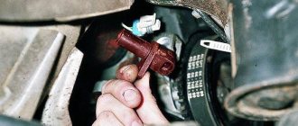
This is what DPKV looks like
The threat of device failure is fraught with the fact that if the DPKV fails, starting the engine will be impossible.
Design and principle of operation of the crankshaft sensor
In order for the sensor to transmit a signal through a wire to the ECU microcontroller, the following principle is used:
- two flywheel teeth were deliberately omitted;
- when entire flywheel teeth rotate near the DPKV, they distort the magnetic field arising in the device coil;
- when a section of the crown with a missing tooth passes near the sensor, the interference disappears;
- the device transmits a signal about this to the computer, and the computer determines the exact position of the pistons in each cylinder.
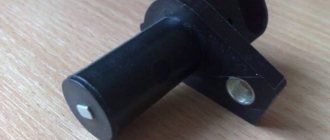
DPKV design
Correct operation is possible only with a gap of 1 - 1.5 mm between the teeth of the flywheel ring and the electrode of the device. Therefore, there are adjusting washers above the DPKV mounting socket. And the 0.5 - 0.7 m long wire suitable from the ECU is equipped with a turnkey connector.
The ECU software allows you to calculate the position of the pistons in cylinders I and IV when a signal is received and the direction of shaft rotation. This is enough to correctly generate signals to the fuel supply and ignition sensor.
Optic
Structurally, this sensor is made of an LED and a receiver. The signal appears in the receiver when it passes through a section of the flywheel with ground teeth, since at this moment the LED beam is not blocked by the remaining intact teeth.
Optical DPKV
These simple steps do not allow you to use the device for any additional operations. If a breakdown occurs (ignition desynchronization), the DPKV is replaced along with the wire.
Hall Sensor
Working on the principle of potential difference in the cross section of metals (Hall effect), the crankshaft position sensor has the additional function of distributing ignition into the combustion chambers of the cylinders.
Hall Sensor
A fairly simple operating principle of the sensor is based on the generation of voltage due to a change in the magnetic field. Without a flywheel with two ground teeth, this device will not work.
Inductive
Unlike previous modifications, the magnetic crankshaft position sensor operates on the basis of electromagnetic induction:
- a field is constantly generated around the device;
- voltage for the signal to the microprocessor occurs only when passing through a section of the flywheel rim with missing teeth.
Shaft position monitoring is not the only option of this device; in addition, it serves as a shaft speed sensor.
Magnetic DPKV
Since the magnetic device and Hall sensor are multifunctional devices, they are most often used in engines.
Signs of sensor malfunction
Since fuel dosing and the ignition system are adjusted based on the signals of this sensor, its malfunction leads to signal distortion and, as a result, interruptions in the functioning of the power plant or the inability to start.
Signs of a broken crankshaft sensor are:
- the engine does not start and the “Check engine>” signal;
- difficulty starting the engine;
- instability of engine operation under different modes;
- a noticeable drop in engine power for no apparent reason;
- When the load increases, engine detonation appears.
If at least one of these malfunction indicators appears, you should find out whether the sensor is the cause of the engine malfunction. But to do this you need to know how to check the crankshaft sensor.
Problems starting the engine
Variants of crankshaft sensor malfunction affecting the internal combustion engine:
- The engine does not start. When you turn the key in the ignition, the starter turns the engine and the fuel pump hums. The reason is that the engine ECU, not receiving the signal from the crankshaft position sensor, cannot correctly direct the command: in which cylinder to give a spark, and in which to open the injector.
- The engine warms up to a certain temperature and stalls or does not start in severe frost. There is only one reason - a microcrack in the winding of the PCV sensor.
Unstable engine operation in various modes
This happens when the DPKV is contaminated, especially when metal shavings or oil get on it. Even a slight impact on the synchronization sensor of magnetic microchips changes its performance characteristics, because the meter is highly sensitive.
Presence of engine detonation with increasing load
The most common reason is a failure of the measuring device, as well as a microcrack in the winding that diverges due to vibration, or a split in the housing into which moisture enters.
Signs of engine detonation:
- disruption of the smooth combustion process of the fuel-air mixture in the internal combustion engine cylinders;
- pops in the receiver or exhaust system;
- misfires;
- a clear decrease in engine power.
Reduced engine power
Engine power drops when the command to supply the air-fuel mixture is untimely. The cause of the malfunction is the delamination of the damper and the shift of the toothed star in relation to the pulley. Motor power is also reduced due to damage to the winding or housing of the crankshaft position meter.
To change or not to change?
Let’s make a reservation right away: before deciding that the DPKV needs replacement, you need to check:
- Condition of the wiring going to the DPKV;
- Availability of high-quality contacts in the circuit;
- No damage to wire insulation;
- No oil on the crankshaft position sensor. Since the oil pump is located next to the DPKV, oil leakage can also cause its malfunction.
Functional crankshaft position sensor
If you have already examined everything, you need to check the sensor itself. But to do this you need to remove it.
Where is and how to check the crankshaft sensor
The fastest and most economical way would be diagnostics with a personal ODBII scanner. If you don’t have a device, we recommend paying attention to the budget Korean-made scanner Scan Tool Pro Black Edition .
First of all, you should inspect the sensor itself. If no traces of dirt or chips are found at the end of the DPKV, you should connect a scanner and read the existing error codes from the ECU. Problems associated with DPKV will be indicated by fault codes - P0335 or P0336, depending on whether a signal is received from the sensor at all. If there are errors, you should clear them using a scanner and test drive the car to see if they reappear. If it reappears, proceed to check the sensor itself using the methods described in the next section. Since Scan Tool Pro runs on a 32-bit chip, it can show you all these moments and save them in memory. It can also be used to diagnose not only the engine, but also other components and assemblies of the car (gearbox, transmission, auxiliary systems ABS, ESP, etc.).
Before checking, you need to know where the crankshaft sensor is located in order to remove it from the car. Since the synchronization disk is located on the drive pulley, you need to look for it there. It is located not far from the disk, it is installed in its seat and secured with one or two bolts. Before removing, its wiring must be disconnected from the chip.
The crankshaft position sensor is located on the engine flywheel housing
When dismantling, it is important to mark its position, so that later it can be correctly placed in its seat. First you need to give a visual assessment of the condition of the sensor. Its body should not be damaged. Over time, the core of this sensor can become covered with dirt, which can also affect the readings. Before checking, it must be thoroughly cleaned of dirt. To do this, you can use a rag soaked in alcohol or gasoline.
Cooling system problems
If you notice that the operating temperature of the VAZ 2114 engine does not correspond to the norm (both up and down), then first of all the reason should be looked for in the cooling system.
Its most important components that directly affect engine temperature are:
Thus, the first thing to check when the engine overheats is the radiator.
There are only 3 main reasons why it may not function correctly:
- Lack of coolant in the system.
- Cooling grid clogged.
- Leak.
In the first case, you should check the fluid level and, if necessary, top it up. In the second case, you will have to dismantle the radiator and clean it (both internal and external purging). In the third case (if a leak is detected), you can either use soldering or use a special sealing compound for radiators, and then add coolant to the normal level.
The next thing you have to check when troubleshooting is the cooling system pipes. With prolonged use, they can become “obsolete” with the further formation of cracks, which may result in a leak of coolant. If it turns out that the pipes have indeed leaked, they should simply be replaced with new ones, and the problem will be solved.
Checking the crankshaft sensor
Checking the condition of the sensor can be superficial, in which only the resistance of its winding is measured, or deep, in which all basic parameters are checked. Let's consider both types of checks:
Measuring the resistance of the crankshaft sensor winding
- For a superficial check, it is enough to have only an ohmmeter. Using this device, the winding resistance is measured. This indicator may differ on different cars, but usually it is 550-700 Ohms. If during measurement the resistance reading is greater or less, the sensor is faulty.
- An in-depth test is more complex and will require a megohmmeter and an inductance meter.
A megohmmeter measures the insulation resistance of the sensor when a voltage of 500 V is applied to it; at this voltage, the resistance should exceed 20 MOhm.
An inductance meter checks the inductance of the sensor. For a working sensor, this indicator should be at the level of 200-350 MHz.
Visual inspection
Since the sensor is installed with a gap adjustment, you must first check this distance with a caliper. The next steps to check the crankshaft sensor visually are:
- identification of foreign objects between it and the flywheel;
- presence of dirt in the area of missing teeth of the synchronization disk;
- wear or breakage of teeth (very rare).
DPKV inspection
In principle, at this stage the car owner does not face any difficulties. Further checking should be done with instruments, preferably a multimeter (tester), which can be switched to ohmmeter, voltmeter and ammeter mode.
Ohmmeter test method
This method is simple and accessible, but does not guarantee detection of a breakdown. It is used to measure the resistance of the coil. To do this, it is enough to simultaneously touch the coil terminals with the probes. The polarity of the touch is not important in this case.
The resistance value depends on the characteristics of the coil and is usually in the range of 500-700 Ohms. To determine the resistance value of your sensor model, you need to look in the description of the DPKV or search on the Internet.
The multimeter is used as follows:
- We set the measured parameter (resistance) in a range close to the measured value, but not lower.
- We touch the ends of the sensor with the probes and look at the readings.
If the indicators are close to the standard values, then the coil is working properly. The disadvantage of this method is that it does not always indicate a faulty crankshaft sensor. Therefore, it is advisable to check using other methods.
Checking inductance values
When excited, all coils display an inductance indicator, including the coil located in the crankshaft sensor housing. The diagnostic method boils down to measuring this indicator.
When checking inductance, you must have a megohmmeter, a network transformer, an inductance meter and a voltmeter. To determine the indicator, carry out the following steps:
- Use a multimeter to measure the inductance of the coil (standard values are in the region of 200-400 mH).
- Using a megohmmeter, measure the resistance of the insulating layer between the ends of the DPKV (the data should be above 0.5 MΩ).
- A network transformer is used to demagnetize the sensor coil (deviations indicate the need to replace the part).
Step #1
You should focus on inductance results in the range of 200 - 400 mH
.
The multimeter supports the function
, you need to connect 2 multimeter probes to 2 coil terminals, polarity does not matter.
The multimeter does not support the required function
, to check we use an inductance meter.
Step #2
You will need a megohmmeter set to an output voltage of 500 V. Check the insulation resistance between the coil wires at least 2 times! The insulation resistance value should not be lower than 0.5 MOhm.
Step #3
At step No. 2, magnetization of the coil “interturn short circuit” may appear, as a result of which the data will be incorrect. It is necessary to use a network transformer, then repeat step No. 2.
Diagnostics using an oscilloscope
The most advanced and accurate method of determining the health of a part is checking with an oscilloscope. Diagnostic work is carried out with the power plant running.
You can also use an oscilloscope to check serviceability on a dismantled crankshaft sensor. This requires an electronic oscilloscope and special software. In this case, the check is carried out according to the algorithm:
- Probes must be connected to the terminals of the crankshaft position sensor;
- Launch the software;
- Move any metal object near the part.
If the sensor is working properly, a graph is constructed on the device screen based on the DPKV readings.
If the part reacts to the movement of a metal object, then it is working. But the result of checking it on a running internal combustion engine will be more accurate.
The simplest, most reliable and fastest way to determine the performance of the DPKV is to install a known-good synchronization sensor in place of the one being tested. And if the problems with the car disappear, then the conclusion is clear - the part is faulty and needs to be replaced.
When installing, you should take into account the correct installation: maintaining the required gap between the DPKV and the flywheel. You can find out this indicator from the instructions for the sensor or from the Internet, but on average it is 0.5-1.5 mm.
Checking with a multimeter (winding resistance)
You don’t need any tools, just prepare a multimeter in advance, since diagnostics will be carried out with its help:
- First, you should dismantle the regulator, and then fix its original position on the motor. You can determine the location of the device from the service manual. So, you need to fix the regulator, while noting its position using the marks.
- After this, just in case, carry out a visual diagnosis of the sensor; perhaps the cause of its malfunction is damage to the housing or wires. The device itself, together with the contacts, must be cleaned and wiped; fuel can be used for these purposes.
- When you dismantle the device, pay attention to the distance between the synchronization shaft and the core. The best option would be if this gap is not lower than 0.6 mm and more than 1.5 mm. If no mechanical damage is detected, then you still have to use a multimeter. In particular, it will be necessary to diagnose the electronic component of the DPKV, namely its winding, since in most cases the problem lies precisely in it.
- The winding diagnostic procedure involves checking the resistance. If you know how to use a multimeter, then this process will not cause you much difficulty. The resistance value for a working sensor should be from 55 to 750 Ohms, however, before checking, we recommend that you read the service book for your car. As a rule, the working interval is indicated there. If, during diagnostics, the signal differs from what it should be, then most likely the problem is a malfunction of the DPKV. Change the regulator before it causes you to become unable to start the car.
Resistance check
The third tester diagnostic method is a comprehensive one, which allows you to measure insulation and inductance.
For this diagnosis you will need:
- network transformer;
- megohmmeter;
- inductance measuring device;
- voltmeter, preferably digital.
This is what the DPKV signal indicators look like when checked with an oscilloscope
This is what the DPKV signal indicators look like when checked with an oscilloscope
It is better to carry out the check in the garage, and it is desirable that the temperature be around 20-22 degrees, this will allow you to take more accurate readings. Here you will also need to measure the winding resistance, we talked about this in the first method.
- Once the resistance has been measured, it is necessary to determine the inductance value; use a meter to do this. If DPKV is working, then this indicator should vary around 200-400 mH.
- After this, take a megohmmeter; you will need to measure the insulation value. In the case when the voltage is about 500 volts, the insulation resistance should be no more than 20 megohms.
- If the timing shaft is magnetized, you will need to demagnetize it, otherwise the engine will not work. To do this, use a network transformer. Having taken all the indicators and analyzed them, we can draw a conclusion about the serviceability or failure of the regulator. Of course, if the indicators deviate from the norm, then the device can be considered inoperable and, accordingly, it needs to be replaced.
When installing a new regulator, pay attention to the previously marked marks that you placed when removing the DPKV. Do not forget also that the distance from the core to the synchronization shaft should vary around 0.5-1.5 mm.
Controller diagnostics
Diagnostics of the crankshaft position sensor is carried out on the dismantled controller. It is recommended to set a timing mark on the crankcase before removing it so that when installing a new element, the correct gap between the tracking device and the timing disk will be maintained. The permissible gap is 0.6–1.5 mm.
We remove the element with a 10mm wrench and carry out a visual inspection. Before checking the crankshaft sensor, the battery is disconnected and the contact points are checked. During a visual inspection, the integrity of the housing, wires, connectors, and the absence of cracks and dents on the housing are checked. If there are no signs of mechanical damage, the DPKV is checked with a multimeter.
Testing of the node can be carried out both by resistance and voltage parameters. Testing for resistance is much simpler, so it is used in most diagnostic options.
The resistance on the working controller winding should be in the range of 550–750 Ohms. Measurements are taken on two contacts of the part. For a 16-valve injector engine, a resistance deviation of 5% is considered acceptable.
Drivers rarely use the second testing option, although diagnostics with a voltmeter are considered more reliable. To check, you will need a transformer and an inductance meter, for example, the MY-6243 multimeter model is often used to measure capacitance and inductance. Checking step by step.
- Calculate the inductance dpkv. The working element at a voltage of at least 500 mV will show an inductance in the range of 200–4000 iH.
- Check the resistance; a working sensor shows a parameter of 20 mOhm.
Check for VAZ 2110
Using an ohmmeter (multimeter). To make it more clear, let’s look at each method of checking the crankshaft sensor using the example of several cars.
The first will be the VAZ-2110, which uses an induction type of device.
So, the engine on the “Ten” malfunctioned and there is every assumption that this happened due to the crankshaft sensor. There is a multimeter at hand that can work in ohmmeter mode.
This is quite enough to check the winding resistance.
The first thing to do is to inspect the device while it is installed on the car, or rather, check for a gap between it and the synchronization disk.
It is quite possible that there is no gap there due to the fact that dirt has adhered to the sensor or disk, which led to malfunction.
If everything is in order with the gap, we will remove the device from the car.
On the VAZ 2110 it is located on the oil pump cover.
Before doing this, it is better to mark the position of the DPKV.
The next stage is assessing the external state. The sensor body must be intact, without signs of damage, the core must be clean, the contact terminals must be free of traces of oxidation, and the wires must not be damaged.
If external contamination is visible on the DPKV, you can wash it before checking (to do this, use only pure gasoline or alcohol), and also clean the contacts with a file.
After cleaning, rinsing and drying, you can start taking measurements. To do this, switch the multimeter to ohmmeter mode and connect the probes to the sensor contacts.
When measuring, a working DPKV should show a resistance in the range of 550-570 Ohms.
For other cars, this indicator may be different, so it is better to inquire about the rated voltage of the sensor in the technical documentation of the car before taking measurements.
If the resistance value is lower or higher than the specified range, the sensor is faulty and must be replaced.
This is the easiest way to check DPKV, but it is also the most inaccurate. It can only give a partial idea of the state of the device, although this is sometimes quite sufficient.
An oscilloscope.
The most accurate method for checking is using an oscilloscope. Therefore, let’s look at how to check the sensor on a VAZ-2110 using this device.
During such a check, there is no need to remove the DCP, and all measurements are taken directly on the car.
Before carrying out the test, you need to correctly connect the oscilloscope to the machine. Typically this device has one clamp and two probes.
The clamp must be connected to the engine ground, that is, to any metal component of the motor.
One probe is installed parallel to the sensor signal output terminal. The second probe is connected to pin 5 on the scanner connector.
After connection, you should switch the device to the “Inductive Crankshaft” mode.
After this, start the engine. If it does not start, then you will need to rotate the crankshaft with the starter so that the oscilloscope takes readings.
After this, the performance of the sensor can be assessed from the resulting oscillogram. Any disturbances in its operation will affect the oscillogram image, and this will be clearly visible.
Comprehensive check for Opel Vectra B
Now let's take another car and use it to consider the last of the verification methods - comprehensive.
This test is much better than with a conventional multimeter, but in terms of accuracy it is not as accurate as an oscilloscope.
The problem car will now be the Opel Vectra B. We leave the symptoms the same.
The initial work is also no different from the VAZ-2110: the sensor is removed, inspected, thoroughly washed, and only after that you can start checking the condition.
But for a comprehensive check you will need more equipment:
- Multimeter;
- Megaohmmeter;
- A device for measuring inductance. It is better to carry out all measurements in a heated room so that the readings are correct.
First, the coil resistance is measured, as described above. Resistance readings must be within the range specified in the technical documentation.
The next check is to measure the winding inductance, for which a device is used to measure it. A working DPKV inductance should be in the range of 200-400 mH.
The devices are pictured below.
The insulation resistance is also checked with a megohmmeter. When a voltage of 500 V is applied, the resistance value of the sensor should be no more than 20 MΩ.
Based on these measurements, it is determined whether the DPKV is working or requires replacement.
Photos of the devices are below.
Features of testing on other cars
As for other cars, for example, VAZ-2109 with an injection engine, VAZ-2112 and VAZ-2114, their check is carried out identically to the VAZ-2110 car.
It is noteworthy that for VAZs, when checking the resistance of the crankshaft sensor coil, an additional check can be carried out.
But to do this, the multimeter must be switched to voltmeter mode with a measurement limit of 200 mV.
Then connect the probes to the DPKV terminals and pass them with any metal object, for example, a screwdriver, at a short distance from the core.
If the sensor is working properly, it will react to metal, the multimeter will show voltage surges on the display. The absence of these bursts will indicate a faulty element.
As for a car like the Reno Logan, the difference from the VAZ in this car comes down to slightly different readings of the resistance of the sensor coil when measured with an ohmmeter.
A working Logan DPKV has a normal resistance of 200-270 Ohms.
For Daewoo Lanos, the coil resistance should be in the range of 500-600 Ohms.
But on the ZMZ-406 engine, installed on Volga and Gazelle cars, the normal coil resistance is in the range of 850-900 Ohms.
Idle speed control
Where is the oil pressure sensor on a Kamaz
? As in engines with a carburetor, an injection engine keeps idle speed with the throttle valve fully closed. This is possible only under one condition - if the design of the throttle provides for a bypass channel, and it must have a variable throughput. To do this, a conical valve was installed in the bypass air channel of the throttle body, regulating the air supply when the throttle valve is closed, and called it IAC, idle air regulator. It consists of a conical valve, a stem and a stepper motor. Depending on which winding the impulse is applied to, the motor rotates in one direction or the other, thereby changing the throughput of the bypass air channel. The idle either rises or falls as a result of the movement of the cone valve. The idle speed sensor on the VAZ 2115 has catalog number 1148300 02.
How to check
The most common failure of the IAC is a break in the windings of the stepper motor. To check the windings, you need a multimeter turned on in resistance measurement mode. The resistance value between contacts A-B and C-D is within 45-80 Ohms. Otherwise, the regulator requires replacement. There should be infinite resistance between pins AD and B-C. This means that the windings do not short circuit each other. If there is resistance at these contacts, the sensor is replaced. Rated supply voltage is from 7.4 to 14.1 V.
Replacing the crankshaft position sensor
To replace, you must use only a sensor of the type that was previously installed on the vehicle and recommended by the automaker.
Unsuitable sensors can produce measurement errors, which will certainly affect engine performance. Replacing the sensor usually does not cause serious difficulties. To do this, the DPKV must be de-energized by disconnecting the terminal block from the meter. Then you need to use a 10-mm open-end wrench to unscrew the bolt(s) securing the sensor. After this, the meter must be removed from the mounting socket and a new sensor installed in it.
After installing the DPKV, you need to adjust the distance between it and the end of the synchronization disk. It should be from 0.5 to 1.5 mm (the exact data is in the car’s manual). Adjustment is carried out using adjusting washers. After installing the new sensor, the motor should start operating normally. If this does not happen, it is necessary to reset the engine errors and calibrate the sensor.
Bottom line
No matter what kind of car you own, if it has an injection engine installed, then problems with the engine’s operation due to DPKV are quite possible.
Experienced car enthusiasts always keep a spare sensor in their car so as not to be taken by surprise.
After all, it is much easier to install a new element and drive on, and then check the removed one for functionality, than at the most unexpected moment to encounter the fact that the car refuses to work normally due to such a small but very important element as the engine crankshaft position sensor.