Introduction
I went online to search for information on how people connect these Chinese units to a VAZ and came to the conclusion that everyone installs such units in a terribly artisanal way, removing half of the wiring, adding some of their own, and in the end, all this does not “successfully” work. Among the makeshift connection instructions, I came across the only normal article by Soliderus, who installed a similar control unit on his Chrysler; his article helped me a lot. But since we have a harsh domestic auto industry, we had to invent our own connection diagram, but first things first.
Please read this entire article first before disassembling the machine; you may not have any parts on hand or may be missing some of the original wiring.
What does the relay kit with fuse box do?
Why the VAZ-2110 central locking does not work and its repair
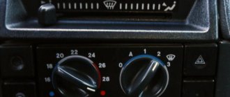
Layout of fuses and relays in the main mounting block of the VAZ-2110
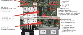
The above diagram describes the location of the main relay kit and fuse box. The following elements are located here:
- K1 is a type of relay responsible for monitoring the health of a set of light bulbs;
- K2 – this component is associated with the operation of the front pair of wipers;
- K3 – behind this designation lies a breaker relay that regulates the operation of the repeater and the vehicle’s alarm sign;
- K4 and K5 – a pair of relays for the injector, which is responsible for turning on the low/high beam headlights of the VAZ-2110;
- K6 - an additional type of relay required to replace one of the burned out ones from the main unit;
- K7 - this element is responsible for turning on the heating function on the rear window;
- K8 - like K6, is a backup relay.
Tip: If you notice the main signs of a faulty oxygen sensor. You should look at the fuses first. If everything is in order in the mounting block, then you should seek help from a car service for diagnostics.
Theory
Before starting the installation, I want to warn you about the characteristics of my particular VAZ 2114 car (2006 model year, “Lux” equipment, the wiring under the dashboard is numbered as “VAZ 2115-...”), since I myself, from personal experience, have seen “four” and “tags” of the same year of manufacture, the same configuration, but with completely different wiring (I assume that this was due to different supplies of wiring to the conveyor).
After looking at the information on the Internet, I came to the conclusion that the overwhelming number of people install the control unit according to the wrong diagram “D”, from the instructions, which will not fit the Samar family (VAZ 2108/09/99/13/14/15) , since the opening and closing of doors (or rather, the supply of a signal to the BUDU (Door Lock Control Unit)) in Samara is controlled by a “minus”, and according to the “D” scheme, control occurs by supplying a “plus” to the BUDU. As I found out, this scheme only works when the standard BUDU is removed and the BU works every other time and only one button on the control key works. In my case, when connecting circuit “D” (I tried to connect it together with the BUBD), I burned several fuses and started looking for another connection method.
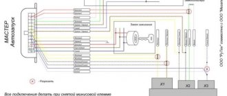
The scheme we need and works is scheme “C”
Scheme C
According to this scheme, our control unit will send a “minus” signal to the BUDU and everything will work normally, without removing the BUDU itself.
Installation
To begin with, I determined which wires in the control unit block I needed and which I did not.
I didn't need:
- — green wire — glass closer;
- — blue wire — trunk opening;
- — pink wire — siren (there was a siren, but I just didn’t want to install it);
Also, orange and orange-black wires are not needed, since according to scheme “C” they are not needed.
We still have:
- — red — “plus” 12v to the battery;
- — black — “minus” 12v (I connected the minus to the body, since the control unit does not necessarily require a minus power supply from the battery);
- — yellow and yellow-black — connect to the negative (I connected them to the main negative and all 3 wires to the body);
- - 2 brown ones - they supply a plus to the alarm button (some people connect them to the dimensions);
- — white — it sends a minus for closing;
- - white-black - it sends a minus to the opening.
For clarity
Used block with signatures
The control unit was installed on self-tapping screws, on the lower plastic part of the panel (to the left of the steering wheel height adjustment lever, next to the hood opening handle), but you can install it as you wish.
Plus, I stuffed it into the cambric and passed it through the rubber of the headlight range control, making a small hole with an awl (I couldn’t find a more convenient place, without drilling, in the whole car):
Positive wire
Under the hood I connected the plus directly to the standard terminal, tightening the bolt to “10”:
Positive terminal
I started connecting the emergency lights. I read on the Internet that you need to disassemble the hazard warning button, solder something, short circuit something, and in general it turns out that this round button interferes with normal steering and everywhere they show how to redo it.
In general, I did not find a complete pinout of the button, using a general electrical diagram and the scientific “poke method” I found out that:
- — blue-black wire — left turn;
- - blue wire - right turn
Hazard warning button block
I again stuffed the two brown wires into the casing and brought them to the emergency flasher button block, pulled out the blue-black and blue wires from the block, using a small awl and “someone’s mother,” and soldered the brown wires directly to the “mother” terminals, so how I didn’t want to cut off the factory terminals (you don’t need a lot of tin, because if there is a lot of it, the terminals won’t fit back into the block):
Emergency signal block with soldered brown wires BU
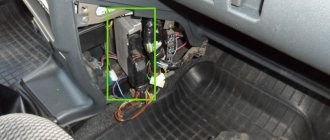
Removing the BUDU turned out to be not an easy task; it is located above the hood release handle, almost under the dashboard, in general in not the most convenient place.
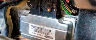
I have installed BUBD 21093-6512010-03 NPO Itelma.
BUBD 21093-6512010-03 NPO Itelma
This BUBD was installed on all Samara II (VAZ 2113/14/15), I’m not sure about the Samar I (VAZ 2108/09/99), check whether the BUBD is the same on your car, because the pinout may differ.
The wires we need in the BUBD block:
- — brown — door closing;
- - blue - opening doors
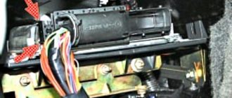
By analogy with the emergency gang, I soldered the wires to the terminals according to the diagram:
- — brown from BUBD with white from BU;
- — blue from BUBD with white and black from BU
BUBD block with soldered wires from the control unit
Now the most interesting part is the driver's door.
We remove the door trim, remove the black “anthers” from the inside.
There are several options:
Option 1) You have a certain “microswitch” in the driver’s door, which, when you open the driver’s door with the key, sends a signal to the ECU and it opens the other doors (another name for such a switch is central locking, since without such a switch you would have to close each door separately). The driver's door motor is missing. There is also a block with two wires in the driver’s door: one is red, the other is yellow (the same blocks are 100% in the other 3 doors of the car) they supply power to the electric motor, which opens/closes the door lock.
Option 2) Everything is the same as in point 1, but the block with the red and yellow wires is missing (a very common situation, especially if the equipment is not “Lux”). In this case, you need to pull these wires from the ACU to the driver's door (the diagram of the door lock system will be below).
Option 3) You have/have had a non-standard alarm installed and now you have more wires in the driver's door than in the entire car. Here I can’t tell you anything, since I myself have not installed a non-standard alarm system in Samara, try to figure it out using a diagram of the door lock system.
Shown here is an unmodified VAZ 2114/15 (may be the same as the VAZ 2109/99):
Door lock system diagram
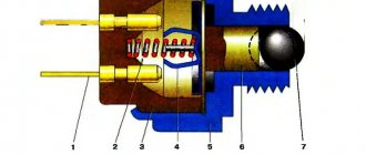
We have the first scenario, which means we must first remove the “microswitch”.
Microswitch
Replacing the driver's door lock mechanism, connecting the central locking via 5 pins. starline activator
Good day to all! It was possible to eliminate the problem with the tight opening (jamming) of the outer door handle through many ways and tests, namely: At first, adjusting the pull on the outer door handle did not help. Then I decided to change the lock mechanism - I took the lock from the store, it turned out to be of poor quality and after installation it was all loose and began to jam worse than the old one, I had to remove it and install the old one temporarily and at the same time remove the outer handle of the driver's door (the old model) and wash the moving elements with carburetor cleaner to prevent the trigger from sticking in the open position, there was a lot of dirt