What data goes to the controller
The Priora ECU operates in the mode of continuous reading of information from sensors. Based on this information, the computer makes decisions about changing the operating modes of the engine systems. The types of data entering the controller are as follows:
- electrical voltage in the car network;
- presence of detonation in combustion chambers;
- vehicle speed;
- cooling system temperature;
- amount of oxygen in exhaust gases;
- air flow;
- temperature of the air entering the intake manifold;
- position of the camshaft and crankshaft;
- throttle position.
Where are the sensors located?
All modern Lada cars (Granta, Kalina, Priora, Vesta, Largus, Niva or Lada XRAY) are equipped with domestic VAZ engines. The location of the sensors on these motors is the same:
Elements of the electronic engine control system of the VAZ 11186/11189: 1* – controller; 2* – crankshaft position sensor; 3* – control oxygen concentration sensor; 4* – diagnostic block; 5* – diagnostic oxygen concentration sensor; 6 – throttle control unit; 7* – vehicle speed sensor; 8* – adsorber purge valve; 9* – gas pedal module; 10* – brake signal switch; 11* – clutch pedal position sensor; 12 – battery; 13 – mass air flow sensor; 14 – coolant temperature sensor; 15 – ignition coil; 16 – knock sensor; 17 – spark plugs; 18* – nozzles. *The item is not visible in the photo.
Location of ECM elements in the vehicle interior (for clarity, without dashboard): 1 – clutch pedal position sensor; 2 – brake signal switch; 3 – gas pedal module; 4 – controller.
What does the controller control?
After processing the information, the Lada Priora ECU makes adjustments to the operation of the following mechanisms:
- ignition systems;
- cooling systems - controls the operation of the fan;
- fuel system (operation of injectors and fuel pump);
- interior climate control systems (air conditioning operating modes);
- exhaust gas vapor recovery systems;
Control occurs by closing the output circuits through the output transistors.
Types of ECU memory
In order to perform its functions, the controller has to operate with a lot of data. Some of them are constantly in operation, others are loaded periodically. Therefore, memory is divided into three types:
- PROM is a programmable read-only memory device. It contains the so-called firmware - a program that controls engine operating parameters, such as fuel injection timing, ignition angle advance control, idle speed, as well as calibration data. This type of memory is retained when there is no power. Data changes are made using reprogramming.
- RAM is a random access memory device. Performs the same function as the RAM of a regular computer - temporary storage of information during one working session. This memory receives sensor data, stores diagnostic codes, as well as intermediate information about the activity of the microprocessor. It requires electric current to operate.
- EPROM is an electrically programmable memory device. This type of memory is part of the standard anti-theft system. When starting the engine, the immobilizer control unit transmits codes to the Priora ECU, where password codes are located that allow or prohibit the start. In addition, the EPROM records deviations in engine operation. This memory does not depend on the supply of electricity and stores information in the controller permanently.
Brains (ECU) for VAZ 2114: what is it, what are they, is it possible to repair them
The electronic engine control unit (abbreviated names ECM, engine ECU) can simply be called the “brain” of the fourteenth. This is a device that combines all the equipment and communications of the VAZ 2114 into one system and makes them work as a single whole.
In this article we will understand what an ECU is, where it is located, what devices can be installed on the fourteenth, as well as how electronic engine control units are repaired and what are the features of their diagnostics.
Controller VAZ 2114
Operating principle and location of the device
The electronic engine control unit starts working when the ignition is activated; it continuously functions while driving, collecting information from various fourteenth sensors. The received information is analyzed by the processor and, based on the results of the analysis of the received data, the device controls the functional systems of the VAZ-2114.
The VAZ 2114 engine control unit receives information from the following fourteenth sensors:
Based on the information received, the ECU on the VAZ 2114 controls the following systems and components of the vehicle:
- Adsorber;
- Ignition system;
- Injectors and fuel pump;
- Ventilation;
- Automatic diagnostic programs;
- Idle speed control unit.
The brains on the VAZ 2114 consist of 3 separate devices, each of which has an individual type of memory:
- Random access storage device - a RAM block is a system with short-term memory. RAM contains information about recent errors that the ECU detected in the fourteenth systems and various current vehicle parameters. The RAM memory is completely updated when the ignition is turned off.
- A programmable permanent storage device is the main memory unit; it stores the ECU firmware. The PROM contains information about the results of calibrations of the fourteenth systems, as well as the power unit control algorithm. The EPROM memory is permanent; it is stored when the ignition is turned off. With certain skills, the EPROM block can be reprogrammed, which will improve the power and dynamics of the VAZ 2114.
- An electrically reprogrammable storage device is the main functional purpose of the unit - protecting the machine. The EEPROM contains data from the fourteenth anti-theft system - passwords and their encoding. It will be possible to start the engine only after the EPROM and the immobilizer compare data with each other.
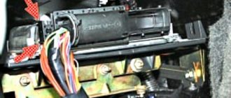
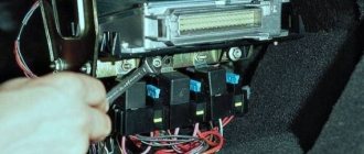
The VAZ 2114 ECU is hidden inside the dashboard, right under the dashboard. In order to get to the brains, you need to use a Phillips screwdriver to unscrew the fixing screws and remove the side panel of the dashboard from the passenger seat. There you will see a longitudinal plastic brain housing, which is inserted inside a stainless steel retainer.
To remove the control unit, you need to unscrew the fixing bolt and pull the lock towards you, after which the device can be freely removed (you must first completely de-energize the car by removing all terminals from the battery).
You remove the panel, and behind it the “brains” - everything is simple!
Types of VAZ 2114 control units
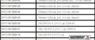
The fourteenth is a car whose production lasted for 12 years. Throughout the entire production cycle, Avto-VAZ engineers were constantly improving the main characteristics of the VAZ 2114. The changes also affected the brains of the car. The VAZ 2114 can be equipped with 8 generations of electronic units from different manufacturers.
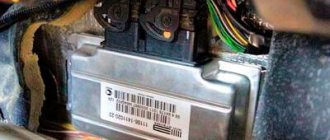
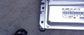
Let's figure out how to find out which ECU is on the VAZ 2114. To do this, you need to look at the device itself - the numbers of the model number are printed on its body, rewrite these numbers and compare them with the markings given in the tables of this article.
Self-diagnosis systems
Like any computer, the Priora ECU has feedback from the user.
The driver learns about problems using signal codes, which can be seen in two ways: using an additional on-board computer connected to the diagnostic connector, and on the instrument panel after performing simple manipulations.
For self-diagnosis, you can install the following devices:
- State X 1 P Priora. A small device that is inserted in place of a standard button. Has an LED display with 3 characters. In addition to the diagnostic function using 30 parameters, it allows you to warm up the spark plugs during cold periods, independently regulate the temperature at which the cooling system fan turns on, and reset engine errors.
- Priora State Matrix. A more serious on-board computer. It is placed in place of the standard clock and has a graphic display of 128 x 32 pixels.
In addition to the functions listed on the previous computer, the device can work with gas equipment, reading gas consumption. The “Afterburner” function allows you not only to reset engine errors, but also to roll back the controller to its factory state, thereby resuscitating it. After activating this option, the “Priors” ECU mode will turn on, which was set at the factory. This bookmaker also has the ability to update the software.
LADA 2170
Instrument panel diagram
1, 2, 3, – instrument panel harness connectors to the front harness 4 – instrument panel harness connector to the rear harness 5 – contacts of the mounting block connector 6 – brake light switch 7 – instrument cluster 8 – lighting control module 9 – driver airbag module 10 – sound signal switch 11 – diagnostic block 12 – on-board computer mode switch 13 – ignition switch 14, 15 – blocks to the electric amplifier control unit 16 – electrical package controller 17 – light alarm switch 18 – windshield wiper switch 19 – air flow distribution gearmotor 20 – block heater control 21 – heater electric motor switch 22 – rear window heating switch 23 – clock 24, 25 – instrument panel harness connectors to the radio 26 – hazard warning switch 27 – glove compartment lighting switch 28 – glove compartment lighting switch 29 – instrument panel harness connector to ignition system harness 30 – airbag system control unit
Front Wire Harness Connection Diagram
1 – starter 2 – battery 3 – generator 4 – battery harness and starter and front harness connectors 5 – 7 – front instrument panel harness connector 8 – engine compartment lamp switch 9 – left headlight 10 – right headlight 11 – brake fluid level sensor 12 – sensor air temperature 13 – washer motor 14 – reverse light switch 15 – engine electric fan 16 – heater damper gear motor 17 – additional resistor 18 – windshield wiper motor 19 – main fuse block 20 – heater motor 21, 22 – sound signal
Ignition system diagram
1 – controller 2 – ignition system harness connector to the instrument panel harness 3 – main fuse box 4 – speed sensor 5 – rough road sensor 6 – oil pressure warning lamp sensor 7 – throttle position sensor 8 – coolant temperature sensor 9 – pointer sensor coolant temperature 10 – mass air flow sensor 11 – idle speed control 12 – fuel pump relay 13 – fuel pump power supply circuit fuse (15 A) 14 – ignition relay 15 – ignition relay fuse (15 A) 16 – controller power circuit fuse (7, 5 A) 17 – crankshaft position sensor 18 – oxygen sensor 19 – phase sensor 20 – knock sensor 21 – canister purge solenoid valve 22 – diagnostic oxygen sensor 23 – ignition coil 24 – spark plugs 25 – injectors 26 – ignition coil wiring harness block to the ignition system harness 27 – ignition system harness block to the ignition coil wiring harness 28 – ignition system harness block to the injector harness 29 – injector harness block to the ignition system harness
And here are the electrical diagrams of the Lada Priora Lux.
CAR ELECTRONICS REPAIR BATTERY CHARGERS
How to perform diagnostics using a standard on-board computer
In the absence of additional diagnostic tools, errors that are read by the Priora ECU can be displayed on the instrument panel in the standard way. To do this you need:
- While holding the mileage reset button, turn on the ignition. After pressing for 4 seconds, the instrument panel begins to move (all indicators light up, instrument arrows rotate around the axis several times, the LCD display turns on all registers). This indicates that the self-diagnosis mode has turned on.
- On the right steering column switch, the Reset button selects the position for displaying the firmware version, error code, and error reset.
If you need to get rid of an engine error, in reset mode, press Reset and hold the button in this position for 3 seconds.
Error codes
In error mode, the computer may display the following codes:
After troubleshooting, you need to reset the error. If no action is performed within 20 seconds, the on-board computer goes into normal operation.
LADA PRIORA 21723
Assignment of contacts of the instrument cluster block
1 To the electric power steering 2 To the hazard warning lamp 3 To the emergency oil pressure sensor 4 To the parking brake switch 5 To the immobilizer control unit 6 To the airbag control unit 7 To the exterior lighting switch 8 To the turn signal switch (starboard side) 9 To the indicator switch turn (left side) 10 To the fuel injection system control unit 11 To the front passenger airbag deactivation sensor 12 To the seat belt sensor not fastened 13 To the control unit of the electronic brake force distributor 14 To the “RESET” button on the steering column switch (-) 15 To the level sensor brake fluid 16 To the control sensor of the anti-lock braking system 17 To the high beam switch 18 To the instrument cluster lighting switch 19 Housing 20 To terminal “30” of the battery 21 To terminal “15” of the ignition switch 22 To the fuel consumption sensor 23 To the function switching mode key trip computer in a ring forward and changing the minutes (-) 24 To the mode key for switching the functions of the trip computer in a ring back and setting the clock (-) 25 To the outside temperature sensor (-) 26 To the outside temperature sensor (+) 27 To the fuel level sensor 28 To the speed sensor 29 To the coolant temperature sensor 30 Low-voltage tachometer input 31 Diagnostics during production of the instrument cluster 32 To the “L” terminal of the generator relay regulator
List of elements of the electrical connection diagram of the rear wiring harness of LADA PRIORA
1 – rear wiring harness block to the instrument panel wiring harness block; 2 – rear wiring harness block to additional wiring harness block 2 (left rear door); 3 – rear wiring harness block to side door wiring harness block (right front door); 4 – left side direction indicator; 5 – electrical package controller; 6 – right side direction indicator; 7 – interior lighting unit; 8 – handbrake warning lamp switch; 9 – left lamp; 10 – right lamp; 11 – interior air temperature sensor; 12 – interior lamp switch in the driver’s door pillar; 13 – switch for the interior lighting in the pillar of the right front door; 14 – switch for the interior lighting in the pillar of the right rear door; 15 – interior light switch in the left rear door pillar; 16 – block of the rear wiring harness to the block of the wiring harness of the side doors 2 (left front door); 17 – block of the rear wiring harness to the block of the additional wiring harness (right rear door); 18 – blocks of the rear wiring harness to the rear right loudspeaker; 19 – blocks of the rear wiring harness to the rear left loudspeaker; 20 – cigarette lighter; 21 – electric fuel pump module; 22, 23 – rear wiring harness blocks to instrument panel wiring harness blocks 2,3; 24 – trunk lighting; 25 – additional brake signal; 26 – trunk lock drive switch; 27 – interior lamp; 28 – rear wiring harness block to the front wiring harness block; 29 – left rear speed sensor; 30 – right rear speed sensor; 31 – sensor for automatic glass cleaning system (rain sensor); 32 – rain sensor sensitivity regulator; 33 – rear wiring harness block to instrument panel wiring harness block 4; 34 – block of the rear wiring harness to the block of the wiring harness of the parking system sensors; 35 – alarm unit for safe parking system; 36 – driver’s seat belt pretensioner; 37 – passenger seat belt pretensioner; 38 – rear wiring harness block to side door wiring harness block 3 (right front door); 39 – airbag control unit; 40 – parking system control unit; 41 – block of the rear wiring harness to the block of the rear additional wiring harness (tailgate); 42 – rear wiring harness block to rear additional wiring harness block 2 (tailgate); 43 – left seat heater; 44 – switch for electric seat heaters; 45 – right seat heater. 46 – rear wiring harness block to the parking system switch.
How to replace the Priora ECU
There can be many reasons for replacing the controller: the desire to install another model that can work with more efficient firmware, failure, incorrect operation.
You can find out which ECU is on the Priora using the diagnostic method, or by using the firmware identifier, which can be checked on a special website. Bosch M 10 and “January-7” controllers are installed on cars.
In order to change the ECU, you need to do the following:
- Disconnect the on-board system from the battery. To do this, simply remove the negative terminal.
- Remove the plastic lining of the tunnel on the right side.
- Push the bracket securing the connector with the bundle of wires all the way.
- Remove the block with wires.
- Unscrew the 2 nuts in the place where the Priora ECU is attached to the bracket.
- Lift the controller up and remove it through the right side.
As can be seen from the description, the procedure is very simple and does not take more than 5-10 minutes. Installation occurs in reverse order.
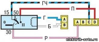
VAZ 2170 ECM harness connection diagram
This part is organized to supply power to the main instruments and engine control system of the Lada Priora. From here, voltage is supplied to the main components, units of the vehicle’s power plant, as well as control sensors and ECUs. The standard electrical circuit connection system (pinout) looks like this:
- 1 – ECU power supply;
- 2 – main block of the electronic system to the dashboard;
- 3 – distribution board;
- 4 – speedometer;
- 5 – road surface roughness sensor;
- 6 – indication of pressure in the engine crankcase;
- 7 – TPS;
- 8 – DTOZH;
- 9 – indication of antifreeze temperature sensor;
- 10 – mass air flow sensor;
- 11 – control XX;
- 12 – main relay of the fuel pump;
- 13 – VT circuit fuse;
- 14 – relay BZ;
- 15 – fuse of the above circuit;
- 16 – ECU fusible link;
- 17 – DPKV;
- 18 – power supply for mass air flow sensor;
- 19 – phase distribution;
- 20 – mixture detonation sensor;
- 21 – EMC for purging the adsorber;
- 22 – diagnostics of the air flow sensor;
- 23 – power supply to the ignition coil;
- 24 – supply voltage to spark plugs;
- 25 – power supply to fuel injectors;
- 26 – terminal from the ignition coils to the ECM;
- 27 – feedback from 26;
- 28 – ECM connector to the injection system;
- 29 – response to the previous output;
- A – phase on the battery;
- B1/2 – ignition mass;
- C1 – mass from short circuit.
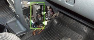
Lada Priora - how to remove the ECU electronic control unit
The electronic engine control unit (ECU) on a Lada Priora car is located under the instrument panel and is an electronic control center that receives signals from all system sensors and, based on this data, the ECU adjusts the operation of fuel injection and other vehicle systems. The electronic control unit is removed to replace it with a new one (it cannot be repaired and is replaced properly in the event of a breakdown) or when carrying out other work in which its presence will interfere with the progress of their implementation. Prepare a standard set of tools and perform the following sequence of actions:
- De-energize the vehicle by disconnecting the negative terminal from the battery.
- Remove the right decorative lining of the floor tunnel.
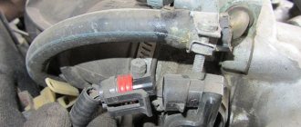
- Now you need to remove the fixing bracket of the connector with wires. To do this, grab it by the two protrusions and move it along the connector plane until it stops.
- Disconnect the connector with wires from the ECU.
- Do not completely unscrew the two nuts securing the control unit bracket.
- And by moving the bracket to the right and lifting it a little, we remove it along with the block.
- Replace or make any other repairs, then install in reverse order.
Clutch and brake sensors
Based on the signals from the clutch pedal position sensor and the brake light switch, the controller distinguishes between pressed and unpressed pedal positions. When the clutch pedal is pressed, the controller disables engine load regulation. Both sensors are located on the pedal assembly.
See "Replacing and Inspecting the Clutch Pedal Sensor" and "Replacing and Inspecting the Brake Pedal Sensor."
Some vehicle versions use an electronic throttle valve drive (E-gas). Let us remind you that in order to understand what errors are recorded in the ECU, you need to decipher them.
Keywords: Lada Granta sensors | Lada Kalina sensors | Lada Priora sensors | Lada Granta engine | Lada Kalina engine | Lada Priora engine | Lada Vesta sensors | Lada Largus sensors | 4x4 sensors | lada xray sensors | lada xray engine | Lada Vesta engine | Lada Largus engine | 4x4 engine | ECM Lada Vesta | ECM Lada XRAY | ECM Lada Largus | ECM Lada Granta | ECM Lada Kalina | ECM Lada Priora | ECM 4x4 | Niva sensors | Niva engine | esud niva | universal article
+16
Found an error? Select it and press Ctrl+Enter..