02/04/2022 21 465 ECU
Author: Ivan Baranov
The electronic control unit is one of the main components of the car, since it is essentially its “brains”. Thanks to this device, many different processes are carried out to ensure normal operation in general, but like any other device, the ECU can fail. Read more about how to check the ECU for functionality and in what cases it is necessary.
[Hide]
Replacing the controller (ECU) and transferring it to Kalina
Welcome! Controller - popularly it is simply called the brain, but scientifically it is briefly called the ECU, that is, the Electronic Engine Control Unit, it performs all electronic functions in the car, starting from instrument readings (Thanks to it, you understand how many revolutions it gives to the engine at one time or another, and you also understand the speed, it is only with the help of it that it is recognized, but also the sensor itself, which transmits this information to the controller) and ending with the very operation of the engine, and therefore if it fails, then all the instruments first of all stop giving readings to you and the car also won’t start, but by changing it to a new one, the car will come back to life again and will drive as if nothing had happened, but it’s best to change it to exactly the same one as it was before, it’s just that all the controllers are configured for certain sensors and for certain engines, but still, if you want, you can install a different model, but you need to make sure that the connector for the wire block in it is exactly the same as on the old one and it is desirable that it has the same dimensions, in addition, you will either have to calibrate it online, or upload a ready-made program (at your discretion and according to your financial capabilities), people also call calibration firmware so that you immediately understand what we are talking about.
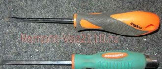
Note! To carry out the work of replacing the controller on a car, you will need to stock up on: Screwdrivers, or to be more precise, you will need a Phillips screwdriver with which you will need to unscrew the screw securing the right facing, as well as a wrench you will need with which you can remove the minus terminal from the battery!
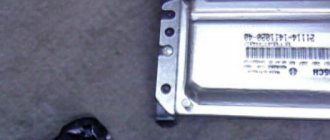
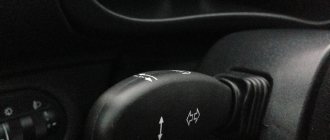
Where is the controller (ECU) located? On all cars it is installed differently and even on Kalina cars, depending on the year of manufacture, it can be in different places, for example on Kalina 2 (We are not considering those in this article) it is located under the carpet and, unlike the first Kalina, completely in another place, on the first Kalinas, unfortunately, the controller is so poorly located that when the stove faucet fails (When it starts to leak), it begins to flood, in connection with this, all its electronics quickly perish and therefore, in a very short time, the controller becomes unusable and must be replaced, for clarity, where it is located on the first Kalinas, you can see in the photo below, the arrow indicates the right facing of the floor tunnel and if you remove it, you will see the controller before your eyes.
Note! Let us give you some advice: when buying your first Kalina, we recommend that the first thing you do is take care of the controller, namely, move it from one place to another, otherwise if the stove faucet starts to flood it, then you will have to look for money somewhere for a new one, and a new controller costs a lot money and therefore you need to take care of the one you have so that you don’t have to replace it with a new one (In this article we will also touch on the topic of transferring this part, so read everything carefully)!
When do you need to change the controller (ECU)? In fact, it’s not so easy to come across a broken controller, because they actually live almost their entire life while the car itself is driving, but it can still either burn out or, due to an unfortunate location, be completely filled with water, coolant, etc. ., maybe, like with the first Kalinas, this happens (on them the controller is located very poorly from the factory), the symptoms of its failure are the loss of communication with the ECU (That is, you connect to it and the computer simply does not see it), as well as incorrect operation of the engine, incorrect operation includes engine tripping, misfires in the ignition system, incorrect operation of fuel injectors (They can either pour and fill the engine in connection with this, or they simply turn off and will not work) and the car may not start, but after these symptoms appear on the ECU, you should think about it last, especially if you have moved it to a place where there is no moisture, just as we have already said, these control units are eternal and almost never fail.
Note! The best way to understand whether the control unit is working or has failed is to install exactly the same unit from a known-good car; unfortunately, it is very difficult to determine its condition simply by looking at it; in addition, the unit can even communicate and show that it is in the car does not have any errors, although it will not start the car itself, or it will, but the car will not work correctly and will not develop its full potential and power!
Advice for motorists
If the ECU is faulty, try to repair it. But not on your own! It is better to entrust such delicate work to experienced craftsmen. A hardware problem most often arises from overheating, a short circuit, corrosion, or a burnt-out capacitor. The latter is the easiest to eliminate: the capacitor is simply soldered, and then you can use your control unit.
Corrosion damage can affect the tracks, and these too can (in theory) be repaired. The work is delicate, requiring skill, special tools, equipment and knowledge. So it’s better to send the controller in for repair and hope for the best.
Often problems with the control unit appear after an accident, even if it did not affect the unit itself. Impact or shock can damage an electronic device. Well, if there is visible damage to the case, this is in most cases a death sentence for the device.
Chip tuning is a lottery. If you want to take a risk (including money for a new ECU), you can try to improve the engine's performance. But such attempts often lead to the opposite effect, that is, a software failure, after which the unit requires flashing (not free, of course).
If you need to determine whether the problem is really in the ECU, or whether the mechanical part is “naughty,” you can find a similar working ECU and temporarily install it on your car. The problems have disappeared - change the control unit, the problems remain - it’s time to take a bow to the mechanics.
What are the types of DS malfunctions?
If this element malfunctions, it is difficult to determine the speed of the vehicle. Photo: avtomarket.ru
In order to promptly fix a breakdown before it develops into a more expensive repair, every owner must listen to the behavior of the car. At the slightest deviation, it is recommended to replace the DS. The main symptoms of malfunctions include:
- Incorrect speedometer readings;
- Fuel consumption increases;
- The engine does not develop full power;
- At idle, unstable operation can be observed.
In this case, each driver will see a Check engine indicator; if there is an on-board computer, error “24” is displayed.
The first thing you need to do is check the condition of the wires and contacts that could simply break. Most often this happens near the connector, where the wires bend and can fray. If the contacts have oxidized or become dirty, they need to be properly cared for. In the area of the exhaust manifold, the integrity of the wire insulation is monitored. In addition, a malfunction of the DS may be associated with a failure of the speedometer cable, which has simply worn out over the years.
How can you test the DS?
Each car owner should know three possible ways to determine the serviceability of the DC; it is necessary to determine whether it produces 12 V. Since the operating principle is based on the Hall effect, the state of the contacts can only be carried out during rotation, and the voltage readings should be within 0.5 V – 10 V.
- Check with a voltmeter. The speed sensor is removed, it is necessary to determine which terminal is responsible for what. One contact of the voltmeter is connected to the terminal that outputs pulse signals, the second is connected to the ground wire. Rotating the sensor, we look at the voltage readings. The faster it rotates, the higher the indicators should be.
- It is not necessary to remove the DS from the car to determine its operation. To do this, you need to lift it with a jack so that the wheel does not touch the ground. Then connect the sensor contacts to a voltmeter, which will give voltage readings when the wheel rotates. If there is a frequency in Hz and voltage, we diagnose that the DS is working.
- It is necessary to disconnect the impulse wire, which is determined by a special controller. As in the previous version, we lift the wheel to rotate it. The “Signal” wire is connected to the control; if the indicator is “-“, then the DS is working. A wire with a light bulb can replace the control in this procedure.
Troubleshooting
Faults are not always related to the part, i.e. The DS may turn out to be quite functional; only some procedures need to be carried out to restore the previous functionality. Photo: drive2.ru
Dirt, dust deposits and oil smudges may form on the DS during the operation of the car. By cleaning this device, you will ensure preventive maintenance of the product and possibly prevent future breakdowns.
The problem may be in the contacts, their fracture, abrasion, and it is necessary to replace the damaged area.
The problem may turn out to be elementary and be hidden in mechanical damage or defects in the cable, which is easier to replace. Having diagnosed the sensor, everyone is convinced that it is not working properly, then it is worth testing and eliminating the above-mentioned malfunctions.
You can learn about some features of speed sensor repair from this video:
Error 1602 VAZ - Interruption of on-board network voltage
Error P1602 on the on-board computers of VAZ 2114, 2110, Kalina vehicles means “On-board network voltage interruption” .
Specifically, the on-board computer recorded a temporary, short-term lack of voltage. The problem can lead to battery drain, voltage drop and other problems. One of the most annoying problems is that the car won’t start at all. Let's figure out the reasons for this error. Most often, the error is associated with poor contact of the wires to ground, from the generator or on the battery terminals. In simple terms: there is contact, but there is no contact. Therefore, to correct error 1602 on domestic cars Niva, Priora, Grant , etc. contacts need to be cleaned .
The main contact from the generator, which should be thoroughly cleaned. It is located below all other contacts and most often loses contact. The wire is to ground, look for it from the negative mark. The wire will go to the housing.
Check the contacts on the battery terminals and, if necessary, clean them of oxides.
If you solved the problem in another way, share it with us in the comments.
Source
The procedure for checking the short circuit
So, there are signs of a malfunction, you should check it.
First of all, the coil must be dismantled. For this you will need:
- prepare a ten-point socket wrench;
- disconnect the terminals on the battery;
- open the protective casing covering the motor;
- press the locking device out of the plastic, disconnect the wiring from the coil terminal;
- remove the fastening bolt;
- pull out the ignition coil.
An inspection is now underway. It should not show any cracks, melts or leaks on the caps and body parts. Only slight smokedness is allowed. Electrics can be checked in several ways. Having installed a working spark plug, we check the device for the presence of a “spark” on the car body. If there is no spark from the coil, then it is quite possible that the short circuit has lost its functionality. In such a situation, you should check the gap in the spark plugs. All work should be performed with rubberized gloves to completely prevent contact of the body or tool with the car body or engine. The fact is that the coil is capable of generating voltage in the range of 20 - 40 kV. Another option is to remove the coil and install it on a good cylinder on another car to perform a drive test. If the short circuit is faulty, it will immediately appear. The third method is instrumental.
The main reasons why the ignition coil breaks are considered to be high temperatures or overheating, which contribute to the formation of cracks. There is a high probability of short circuit failure due to the accumulation of moisture or the formation of corrosion, frequent switching on of the ignition without subsequent starting of the engine, prolonged overloads when an unsuccessful attempt to start the engine.
Controller functions
Location of the controller in the car interior of the LADA PRIОRA family: 1 - controller
The controller controls actuators such as fuel injectors, electric throttle body, heater coil, ignition oxygen sensor, various purge valve and canister relay.
The unit controls the switching on and off of the main relay (ignition relay), through which power from the battery is supplied to the system elements (except for the electric fuel pump, electric fan, indicator unit and control unit for the APS status). The controller turns on the main relay when the ignition is turned on. When the ignition is turned off, the controller delays turning off the main time on the relay, which is necessary to prepare for the next completion (turning on calculations, setting the throttle to the previous position, starting the engine).
Location of the controller in the car interior of the LADA KALINA family: 1 - controller
When the ignition is turned on, the ECU, in addition to performing the above functions, exchanges information with the car's anti-theft system (if the immobilizer is turned on). If the exchange result determines that access to the vehicle is blocked, then the control functions are allowed to continue otherwise. In an engine case, engine operation is blocked.
The controller also performs a system diagnostic function. Its presence determines malfunctions of system elements, turns on the indicator and stores codes in its memory that indicate the nature of the malfunction and help the mechanic carry out repairs.
During vehicle operation and maintenance, disassembling the controller is prohibited.
To monitor the voltage of the output signal controller, a digital voltmeter with an internal resistance of less than 10 MOhm is required.
To prevent damage to the controller when disconnecting the wire from the negative terminal of the battery or the wiring harness from the controller, the ignition must be turned off.
Reasons for ECU failure: what should you be prepared for?
First, the electric control unit of a car, or simply ECU, is a very complex and important computer equipment. If this device malfunctions, all other auto systems may malfunction. In some cases, the car may not work at all, including failure of the box, chargers and control sensors.
Electrical units come in different types and can control different devices. With all this, all systems still intensively interact with each other and transmit important information to regulate all functions. The most basic of them is the car’s engine ECU. Despite its design simplicity, it performs a lot of complex tasks:
1. Control of fuel injection into the combustion chamber of a car.
2. Adjusting the throttle (both while driving and while the engine is idling).
3. Control of the ignition system.
5. Valve timing control.
6. Coolant temperature control.
If we talk specifically about the engine ECU, then all the data it receives can also be taken into account when operating the anti-lock braking system, and when operating the passive safety system, and in the anti-theft system.
The reasons for ECU failure can be very diverse. In any case, this does not bode well for the car owner, since this device cannot be repaired. Even at service stations they simply change it for a new one. But, be that as it may, it is necessary to understand in great detail what can cause a breakdown. With this knowledge, you will be able to ensure that your device is as protected as possible from such troubles in the future.
As auto electricians note, most often the ECU fails due to overvoltage in the car's electrical network. The latter, in turn, can occur due to a short circuit in one of the solenoids. However, this is not the only possible reason:
1. Device failure can occur due to any mechanical impact. This could be an accidental impact or very strong vibrations that can cause microcracks in the ECU boards and the solder joints of the main contacts.
2. Overheating of the unit, which most often occurs due to a sharp temperature change. For example, when you are trying to start a car at high speeds in severe frost, squeezing the maximum out of the capabilities of the car and all its systems.
3. Corrosion, which can occur due to changes in air humidity, as well as due to water entering the engine compartment of the car.
4. Moisture entering directly into the control unit itself due to depressurization of the device.
5. Intervention by outsiders in the design of electronic systems, which could result in a violation of their integrity.
If you wanted to “light up” the car without first turning off the engine.
If the terminals are removed from the car battery without first turning off the engine.
If the terminals were reversed when connecting the battery.
If the starter was turned on, but the power bus was not connected to it.
However, no matter what causes the ECU malfunction, any repair work can only be carried out after a full professional diagnosis has been carried out. In general, the nature of the device malfunction will tell you about malfunctions in other systems. After all, if they are not eliminated, the new control unit will burn out in the same way as the old one. What is the purpose of the engine control unit, how to check the control unit
That is why, in the event of an ECU burnout, it is very important to establish the true cause of the failure and eliminate it immediately
How to independently diagnose the unit?
At first glance, it may seem that diagnosing an ECU is a difficult task that not everyone can handle. Indeed, checking your block is not so easy, but having theoretical knowledge, it is quite possible to apply it in practice.
Required tools and equipment
To check the functionality of the module yourself, you will need to perform a number of steps to connect to the ECU.
To perform the test you will need the following devices and elements:
- Oscilloscope. It’s clear that not every car enthusiast has such a device, so if you don’t have one, you can use a computer with the necessary diagnostic software pre-installed on it.
- Cable for connecting to the device. You need to select an adapter that supports the KWP2000 protocol.
- Software. Finding diagnostic software today is not a problem. To do this, just monitor the network and find a program that is suitable for your vehicle. The program is selected taking into account the car, since different control units are installed on different cars.
Photo gallery “Preparing for system diagnostics”
1. Laptop for testing 2. Adapter for connection 3. KWP_D software for diagnostics
Algorithm of actions
The diagnostic procedure for the electronic control system is discussed below using the Bosch M 7.9.7 module as an example. This control unit model is one of the most common not only in domestic VAZ cars, but also in foreign-made cars. It should also be noted that the verification process is described using the example of using the KWP-D software.
So, how to check the ECU at home:
- First of all, the adapter used must be connected to a computer or laptop, as well as the ECM itself. To do this, connect one end of the cable to the output on the unit, and the other to the USB output on the computer.
- Next, you need to turn the key in the car's ignition, but you do not need to start the engine. By turning on the ignition, you can launch the diagnostic utility on your computer.
- After completing these steps, a window with a message should pop up on the computer screen, which confirms the successful start of diagnosing malfunctions in the controller. If for some reason the message does not appear, you need to make sure that the computer successfully connected to the controller. Check the quality of the connection and connection of the cable to the unit and laptop.
- Then a table should be displayed on the laptop display, which will indicate the main technical characteristics and operating parameters of the vehicle.
- At the next stage, you need to pay attention to the DTC section (it may be called differently in different programs). This section will present all the faults with which the power unit operates. All errors will be displayed on the screen in the form of encrypted combinations of letters and numbers. To decipher them, you need to go to another section, which is usually called Codes, or use the technical documentation for your car.
- If there are no errors in this section, then you now don’t have to worry, since the vehicle’s engine is working perfectly (the author of the video about ECU repair at home is the AUTO REZ channel).
But this verification option is most relevant if the computer sees the block. If you have problems connecting to it, then you will need an electrical diagram of the device, as well as a multimeter. The tester or multimeter itself can be purchased at any specialty store, and the electrical circuit diagram of the ECM should be in the service manual. The diagram itself needs to be studied most carefully; this will be required for verification.
In the event that the ECM points to a specific block, and does not show erratic data, then in accordance with the diagram it needs to be found and called. If there is no accurate information, then the only way out is to diagnose the entire system; as we said above, breakdowns are considered one of the main faults.
After the breakdown is found, it is necessary to check the resistance and determine exactly where the cable is fixed. You will need to solder the corresponding new wire parallel to the old one; if the reason lies in the breakdown, then these actions will eliminate the problem. In all other cases, only qualified specialists can solve the problem.
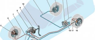
All engine sensors 21116, 21126, 21127
Each sensor is equipped with a connector fixed to its body:
The second contact of the sensor is the housing itself
The smooth operation of the engine is ensured by a set of elements:
The air flow sensor (AFS) is part of the intake system. Not used on engines 21127. The part is designated as 11180-1130010;
Two throttle position sensors - variable resistors, built into the throttle pipe;
The antifreeze temperature sensor is a thermistor with a screw fastening, screwed into the thermostat housing. Catalog number – 21120-3851010;
The knock sensor is a piezoelectric element with two leads, mounted on the cylinder block body. Catalog number – 21120-3855020;
Two oxygen sensors (OS), diagnostic and control, are equipped with a screw mount and are screwed into the exhaust pipe housing. 21074-3850010 is the designation of each module;
The speed sensor is an electronic module, mounted on the top of the gearbox housing. Catalog designation – 21700-3843010;
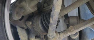
The crankshaft position sensor (CPS) is an electronic module mounted on the oil pump housing. Designated as 21120-3847010;
The phase sensor is an electronic module designated 21120-3706040. 21116 is not used in the engine design;
Oil pressure sensor - has a screw mount, designated as 11180-3829010.
The element indicated under number “9” will be installed at different points depending on the configuration (see photo). The third figure shows where sensor “8” is attached:
The design of the resonant intake system uses a separate sensor that measures air temperature and pressure. The element is designated as 21800-1413010:
Engine air pressure and temperature sensor 21127
The design of the throttle valve modules was not considered. The bug has been corrected below.
For different Kalina-2 engines, their own module, unique in design, is suitable, containing an electrically driven throttle valve:
21126-1148010 – the element is intended for internal combustion engine 21126;
21127-1148010 – part of the engine 21127 design;
21116-1148010 – part of the intake tract of the 8-valve engine (21116).
The module body is made of light alloys and is equipped with a connector to which the contacts of the sensors and the electric motor are connected.
Engine throttle assembly 21126
If necessary, it is better to replace the module as an assembly rather than try to repair it.
What to do if the ECU does not work?
When a source of coolant leakage appears in the designated radiator, it gradually flows onto the electronic module housing. This eventually leads to a short inside the unit and it fails. The intensity of the leak affects the duration of operation of the electronic device until a breakdown occurs.
The owner of the Lada Kalina begins to see an activated indicator, indicating an error in the engine. This can happen for several weeks and at one point the car will stop because the brain has stopped functioning. If the leak intensity is high, then smoke may emanate from under the panel in such an emergency situation. Here, the owner will be required to respond quickly, regardless of the scale of the leak that caused the device to break down.
When it turns out that the brain is filled with liquid, it will need to be examined immediately. The unit is located in the lower compartment of the center console. If the owner is unable to immediately detect the device, we provide a hint in which we localize the search zone: between the interior heating radiator and the floor of the Lada Kalina.
The fastest way to get to the “damaged” module is from the passenger seat. Here we remove the plastic plug on the side surface of the console. It is secured with one screw. After unscrewing, we move this trim to the side (along the direction of the car). Next, we proceed to the direct dismantling of the ECU itself.
The order of manipulations here is as follows.
- Remove the terminals from the battery.
- We unscrew a couple of screws, one of which is located on the motor side.
- Carefully pull the module towards the passenger side.
- For convenience, remove the carpet from the interior for a short time.
- Remove the supply cable harness. Here we use a gentle pulling action, where we grasp the connector latches.
Installing the controller
1) For vehicles of the LADA PRIORA family, attach the bracket to the controller and secure it with screws. Screw tightening torque 1.2…1.6 N.m (Phillips screwdriver, Phillips head, torque screwdriver). Install the controller on the car and secure it with nuts. The tightening torque of the nuts is 1.9…4.5 N.m (spanner 8, replaceable head 8, torque wrench).
For vehicles of the LADA KALINA family, attach the bracket to the controller and secure it with screws. Screw tightening torque 1.2…1.6 N.m (Phillips screwdriver, Phillips head, torque screwdriver). Install the controller on the car and secure it with a screw. The tightening torque of the screw is 1.7…3.5 N.m (Phillips screwdriver, Phillips head, torque screwdriver).
For LADA 4x4 family vehicles, install the controller on the vehicle and secure with nuts. The tightening torque of the nuts is 1.9…4.5 N.m (spanner 8, replaceable head 8, torque wrench).
2) Connect the wiring harness connectors to the controller.
3) Install the screen of the instrument panel console into place (a Phillips screwdriver). For vehicles of the LADA 4x4 family, install the left front upholstery.
4) Connect the wire to the negative terminal of the battery (spanner 10).
Checking the circuit
Before checking the circuit, prepare a multimeter in advance and set it up to work. Next, open the hood and disconnect power from the idle air control. Then you need to set the voltmeter operating mode on the multimeter. The black probe needs to be connected to the ground of the car, and the red one is connected one by one to all the terminals on the block.
Using the help of a second person, start the engine and watch the multimeter readings. The parameters must be within 12 volts. If the multimeter shows a value that is significantly lower than expected, the cause must be sought in the battery, and when the voltage is completely absent, the cause must be sought in the wiring or in the engine control unit
If during verification it turns out that the circuit is working properly, you can focus on the sensor
Video “Why the ECM does not communicate during testing”
From the video below, you can find out why there may be no communication between the ECM and the laptop during diagnostics (the author of the video is the Billye espada channel).
The most common problems with the electronic engine control unit (ECU, ECM, controller) in a VAZ family car.
An electronic engine control unit, abbreviated as ECU, ECM, controller, is an electronic device that, using various signals from engine sensors, controls the composition and amount of fuel supplied to the engine. Having a built-in diagnostic system, it can recognize problems in the system, warning the driver about them through a warning lamp (Check engine). It also stores diagnostic codes that indicate areas of trouble to help technicians make repairs.
Symptoms of a malfunction of the electronic engine control unit:
— Lack of control signals for injectors, ignition, fuel pump, valve or idle mechanism, and other actuators. - No response to Lambda - regulation, temperature sensor, throttle position sensor, etc. - No communication with the diagnostic tool. — Physical damage (burnt radio elements, conductors).
You can purchase an electronic engine control unit (ECU, ECM, controller) from us!
DON'T STROKE - BUY CHEAPER! ! !
Causes of malfunction of the electronic engine control unit:
1. Unqualified intervention in the car’s electrical system when installing alarms and carrying out repairs. 2. “Lighting up” from a car with the engine running. 3. “Reversal of polarity” when connecting the battery. 4. Removing the battery terminal with the engine running. 5. Turning on the starter with the power bus disconnected; 6. Contact of the electrode during welding work with the sensors or wiring of the vehicle. 7. Water entering the ECM. 8. Broken or shorted wiring. 9. Malfunction of the high-voltage part of the ignition system: coils, wires, distributor
ECU diagnostics involves reading errors recorded in the controller’s memory. Reading is performed using special equipment: PC, cable, etc. via diagnostic K-line. You can also get by with an on-board computer that has the function of reading ECM errors.
Troubleshooting
If the engine suddenly starts to “trouble”, then the first thing you should pay attention to is the appearance of the ignition coil. A sign that the part has overheated and eventually burned out are signs of deformation on its body, cracks and irregularities on the plastic surface
To check the ignition coil, you need to use a multimeter, switching the device to resistance testing mode. After this, the contacts of the multimeter must be simultaneously applied to the first and third contacts of the part and thus find out its resistance. If the coil is working properly, then the device should show a value of about 0.5 Ohm with a small tolerance.
The next step in diagnosing the ignition coil is to check the secondary wiring of this part. To perform this procedure, you need to touch the spring located inside the ignition coil cap with a red probe. The black probe must be connected to the second contact. If the device readings are far from the value of 340 kOhm, then things are not very good in this case - it looks like the coil has burned out.
If the multimeter readings are normal, then most likely the ignition coil is working, and the only thing that needs to be done is simply to strengthen its insulation. To do this, you will need a special heat-shrinkable tube (every driver should have it in stock), which must be heated and placed on the reel. This procedure will help cope with the problem of possible current leakage on the Priora.
Sensor selection
You need to purchase a new speed sensor to avoid problems. Visually, the sensor intended for the Priora is almost no different from the Kalina element, and many sellers claim that one model can easily be replaced by another model. Sensors that look similar have completely different fillings, and after installing an inappropriate element, frequent malfunctions in the operation of the ECU and incorrect readings on the speedometer will occur. Therefore, before purchasing, you need to carefully study the old part, rewrite the catalog number and purchase exactly the same model.
https://www.youtube.com/watch?v=7drLW_Qlgj4
VAZ 2114 ECU burned out - what to do?
Obvious signs of this breakdown will be the following factors:
- Lack of control signals for injectors, fuel pump, valve or idle mechanism, etc.
- Lack of response to Lambda - regulation, crankshaft sensor, throttle valve, etc.
- Lack of communication with the diagnostic tool
- Physical damage.
In these cases, it is recommended to purchase a new ECU and replace the faulty one. How to do this is very simple!
Diagnostic options for LADA VESTA electronic control units
The Lada Vesta uses a CAN-type interface, through which signals are transmitted between vehicle systems. Problems are diagnosed using an ELM327 scanner using the OBD2 protocol. List of special functions:
- Rebooting the engine control unit, resetting cruise control, speed limits.
- Training of an automatic transmission during operation. Resetting settings.
- Adaptation of steering sensor, acceleration.
- Reset instrument panel adjustments, multimedia.
- Removing protection, initializing VIN.
- Resetting the adaptation of the power steering, speed sensor, steering angle.
- Download and install one of the scanning programs.
- Carry out diagnostics of the control unit according to the adapter instructions.
- Receive and decipher codes.
- Perform adjustments or repairs to eliminate malfunctions of the device.
- Check again for errors.
Photo source: https://www.drive2.ru/l/551830318525449864/
The scanner is capable of monitoring vehicle modes and parameters while driving via OBD2.
ECU malfunctions
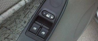
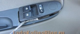
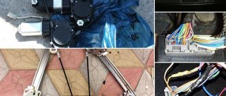
The electronic unit stops working normally when one of the chips in it burns out. Each of the microcircuits is responsible for specific functions. For example, if the windows in a car stop opening on one side, then you need to check the ECU, and not rush to change the entire electric drive. Burnt.
glass fuse (top) and bipolar transistor (coils) at the bottom of the ignition
Frequent signs of malfunctions:
- control signals for the fuel pump, injectors, IAC, valve and no ignition;
- TPS and E-gas are no longer regulated;
- the diagnostic connector does not respond;
- melted wiring.
The contacts of the chips may be burnt, but sometimes the breakdown cannot be visually detected. In this case, you need to remove the unit and take it to a specialist for inspection. Often a failed stabilizer or processor means a replacement controller is needed.
Why do breakdowns occur?
There are a number of reasons for ECU malfunction on Priora and mechanical ones:
- Viburnum damage;
- overheat;
- corrosion;
- broken wrong;
- sealing “lighting” from another car with running damage;
- motor wiring or electrode sensors during welding work.
If the unit fails, it is better to replace it immediately, because problems will begin in the engine operation and errors will constantly be displayed.
Where is the relay and fuse of the VAZ 2114 ECU located?
The main part of the fuses and relays is located in the mounting block of the engine compartment, but the relay and fuse responsible for the electronic control unit of the VAZ 2114 are located in a different place.
Relays and fuses of the VAZ 2114 computer
The second “block” is located under the dashboard on the front passenger side. To access it you just need to unscrew a few fasteners using a Phillips screwdriver. Why is it in quotes, because there is no such block, there is an ECU (brains) and 3 fuses + 3 relays.
Removal and installation instructions
Before changing the DS, you should first carry out a number of preventive actions that can eliminate the malfunction:
- clean the contacts: they may have oxidized;
- Clean the pad, which may have gotten dirty.
The sensor should also be removed, cleaned and checked for functionality.
The check can be performed in three ways:
- Using a multimeter. The positive wire of the removed DC must be connected to the central contact, and the negative wire must be leaned against the body of the car. If the DC is exposed to slight vibration, the readings on the tester should fluctuate from 0.5 to 10 V.
- To check the second method, the device does not need to be removed from the gearbox. You should hang the front wheel, then start rotating it and attach a multimeter in the same way as the first method. If after connection the tester changes readings, then the device is working properly.
- If you don't have a multimeter, you can use a 12 V test light in the socket. The minus must be connected to the signal contact of the DC, and the plus must be connected to the battery. When the light comes on, it indicates that the device is working properly.
If the DS is faulty, it must be replaced.
To replace the DS, you need to prepare the following tools and materials:
- key or head to “10”;
- flat screwdriver;
- Phillips screwdriver;
- rags;
- new device.
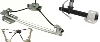
Priorovsky and Kalinovsky speed sensors
Depending on the version, different DS are installed on the Lada Kalina:
The listed DS speeds can replace each other. They can be installed on the following versions of Kalina: 1117, 1118 and 1119 with 1.4 and 1.6 liter engines. The sensor from Lada Priora is suitable, but it cannot be used as it gives incorrect readings.
To carry out the replacement procedure, the car should be put on the handbrake and the hood opened. Replacing the speed sensor on Kalina consists of the following steps:
- To access the speed sensor, you need to either remove the air duct that goes to the air filter or move it to the side.
The process of unscrewing clamps with a screwdriver
- Disconnect the wire block connector from the sensor.
- Using a “10” wrench, unscrew the nut that secures the device. It may be difficult to unscrew the nut, since it is in an inconvenient place. You should find a stop to apply enough force to unscrew.
Unscrewing the nut with a wrench Using a flat-head screwdriver, you need to disconnect the old device from the box and remove it. Next, you should clean the installation site with a rag. Next, you can install a new device.
DS for Lada car
After installing the new device, you need to return the air pipe to its place.
After replacing the device, all signs of its malfunction disappear. Thus, it is not difficult to change the speed sensor on Kalina. Even a novice car enthusiast can handle this, thereby saving on visiting a service station.
Types of ECU (esud, controller). What kind of ECUs are installed on VAZ?
“January-4”, “GM-09”
The very first controllers on SAMARA were January-4, GM - 09. They were installed on the first models before the year 2000. These models were produced both with and without a resonant knock sensor.
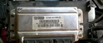
The table contains two columns: 1st column – ECU number, second column – brand of “brains”, firmware version, toxicity standard, distinctive features.
| 2111-1411020-22 | January-4, without DC, RSO (resistor), 1st ser. version |
| 2111-1411020-22 | January-4, without recreation center, RSO, 2nd ser. version |
| 2111-1411020-22 | January-4, without recreation center, RSO, 3rd ser. version |
| 2111-1411020-22 | January-4, without recreation center, RSO, 4th ser. version |
| 2111-1411020-20 | GM,GM EFI-4,2111,with DC,USA-83 |
| 2111-1411020-21 | GM, GM EFI-4, 2111, with DC, EURO-2 |
| 2111-1411020-10 | GM,GM EFI-4 2111,with DC |
| 2111-1411020-20 h | GM, RSO |
VAZ 2113-2115 from 2003 are equipped with the following types of ECUs:
“January 5.1.x”
The following types of hardware implementation are distinguished:
- simultaneous injection;
- in pairs - parallel injection;
- phased injection.
Interchangeable with “VS (Itelma) 5.1”, “Bosch M1.5.4”
| 2111-1411020-71 | January-5.1.1, without dk, with |
| 2111-1411020-71 | January-5.1.1, without dk, with |
| 2111-1411020-71 | January-5.1.1, without dk, with |
| 2111-1411020-71 | January-5.1.1, without dk, with |
| 2111-1411020-71 | January-5.1.1, without dk, with |
| 2111-1411020-72 | Itelma, without dk, with |
| 2111-1411020-72 | Itelma, without dk, with |
| 2111-1411020-72 | Itelma, without dk, with |
| 2111-1411020-72 | Itelma, without dk, with |
“Bosch M1.5.4”
The following types of hardware implementation are distinguished:
- simultaneous injection;
- in pairs - parallel injection;
- phased injection.
Interchangeable with “VS 5.1”, “January 5.1.x”.
| 2111-1411020 | without dk, rso |
| 2111-1411020 | without DC, with (adjustable with scanner) |
| 2111-1411020-70 | BOSCH, without dc, with |
| 2111-1411020-70 | BOSCH, without dc, with |
“Bosch MP7.0”
As a rule, this type of controller is released onto the market and installed at the factory in a single volume. Has a standard 55-pin connector. Capable of working with recrossing on other types of ECM.
“Bosch M7.9.7”
These brains began to be part of the car at the end of 2003. This controller has its own connector, which is incompatible with connectors produced before this model. This type of ECU is installed on VAZ with EURO-2 and EURO-3 toxicity standards. This ECM is lighter weight and smaller in size than previous models. There is also a more reliable connector with increased reliability. They include a switch, which will generally increase the reliability of the controller.
This ECU is in no way compatible with previous controllers.
"VS 5.1"
The following types of hardware implementation are distinguished:
- simultaneous injection;
- in pairs - parallel injection;
- phased injection.
“VS 5.1” is interchangeable with “Bosch M1.5.4”, “January 5.1.x”.
“January 7.2.”
This type of ECU is made with a different type of wiring (81 pins) and is similar to Boshevsky 7.9.7+. This type of ECU is produced both by Itelma and Avtel. Interchangeable with Bosch M.7.9.7. As for the software, 7.2 is a continuation of January 5th.
This table shows variations of the BOSCH ECU, 7.9.7, January 7.2, Itelma, installed exclusively on the VAZ 2109-2115 with a 1.5L 8kL engine.
| 2111-1411020-80 | BOSCH, 7.9.7, E-2, 1.5 l, 1st ser. version |
| 2111-1411020-80h | BOSCH, 7.9.7, E-2, 1.5 l, tuning version |
| 2111-1411020-80 | BOSCH,7.9.7+, E-2, 1.5 l |
| 2111-1411020-80 | BOSCH,7.9.7+, E-2, 1.5 l |
| 2111-1411020-30 | BOSCH,7.9.7, E-3, 1.5 l, 1-gray. version |
| 2111-1411020-81 | January 7.2, E-2, 1.5 l, 1st version, unsuccessful, replace A203EL36 |
| 2111-1411020-81 | January 7.2, E-2, 1.5 l, 2nd version, unsuccessful, replace A203EL36 |
| 2111-1411020-81 | January 7.2, E-2, 1.5 l, 3rd version |
| 2111-1411020-82 | Itelma, dk, E-2, 1.5 l, 1st version |
| 2111-1411020-82 | Itelma, dk, E-2, 1.5 l, 2nd version |
| 2111-1411020-82 | Itelma, dk, E-2, 1.5 l, 3rd version |
| 2111-1411020-80 h | BOSCH, 7.9.7, without DC, E-2, din, 1.5 l |
| 2111-1411020-81 h | January 7.2, without dc, with, 1.5 l |
| 2111-1411020-82 h | Itelma, without dc, with, 1.5 l |
Below is a table with the same ECUs, but for 1.6l 8kl engines.
| 21114-1411020-30 | BOSCH, 7.9.7, E-2, 1.6 l, 1st gray, (buggy software). |
| 21114-1411020-30 | BOSCH, 7.9.7, E-2, 1.6 l, 2nd gray |
| 21114-1411020-30 | BOSCH, 7.9.7+, E-2, 1.6 l, 1st gray |
| 21114-1411020-30 | BOSCH, 7.9.7+, E-2, 1.6 l, 2nd gray |
| 21114-1411020-20 | BOSCH, 7.9.7+, E-3, 1.6 l, 1st gray |
| 21114-1411020-10 | BOSCH, 7.9.7, E-3, 1.6 l, 1st gray |
| 21114-1411020-40 | BOSCH, 7.9.7, E-4, 1.6 l |
| 21114-1411020-31 | January 7.2, E-2, 1.6 l, 1st series - unsuccessful |
| 21114-1411020-31 | January 7.2, E-2, 1.6 l, 2nd series |
| 21114-1411020-31 | January 7.2, E-2, 1.6 l, 3rd series |
| 21114-1411020-31 | January 7.2+, E-2, 1.6 l, 1st series, new hardware version |
| 21114-1411020-32 | Itelma 7.2, E-2, 1.6 l, 1st series |
| 21114-1411020-32 | Itelma 7.2, E-2, 1.6 l, 2nd series |
| 21114-1411020-32 | Itelma 7.2, E-2, 1.6 l, 3rd series |
| 21114-1411020-32 | Itelma 7.2+, E-2, 1.6 l, 1st series, new hardware version |
| 21114-1411020-30 h | BOSCH, dk, E-2, din, 1.6 l |
| 21114-1411020-31 h | January 7.2, without dc, with, 1.6 l |
“January 5.1”
All types of controllers of their type are built on the same platform and most often have differences in the switching of injectors and the DC heater.
Let's look at the following example of ECU firmware January 5.1: 2112-1411020-41 and 2111-1411020-61. The first version has phased injection and an oxygen sensor, the second version differs only in that it has parallel injection. Conclusion - the difference between the ECU data is only in the firmware, so they can be interchanged.
| 2111-1411020-61 | January5.1, dk, E-2 |
| 2111-1411020-61 | January5.1, dk, E-2 |
| 2111-1411020-61 | January5.1, dk, E-2 |
| 2111-1411020-61 | January5.1, dk, E-2 |
| 2111-1411020-61 | January5.1, dk, E-2 |
| 2111-1411020-61 | January5.1, dk, E-2 |
| 2111-1411020-61 | January5.1, dk, E-2 |
| 2111-1411020-62 | Itelma, dk, E-2 |
| 2111-1411020-62 | Itelma, dk, E-2 |
| 2111-1411020-60 h | BOSCH, without dk, reg.SO |
| 2111-1411020-61 h | January 5.1, without dk, with |
| 2111-1411020-62 h | Itelma, without dk, with |
“M7.3.”
Wrong name – January 7.3. This is the last type of controller that is currently installed at AvtoVAZ. This type of ECU has been installed since 2007. on a VAZ with EURO-3 toxicity standard.
The manufacturers of this ECU are two Russian companies: Itelma and Avtel. Below, the table shows ECUs for engines with EURO-3 and Euro-4 toxicity standards.
| Euro-3 engine 1.6, 8 cells | |||
| Avtel 21114-1411020-11 E-3 | 1st, 2nd and 3rd versions | ||
| Itelma 21114-1411020-12 E-3 | 1st, 2nd and 3rd versions | ||
| Euro-4 engine 1.6, 8 cells | |||
| 11183-1411020-02 Samara | Electronic pedal | ||
Purpose of the DS
Measuring driving speed is the main, but not the only function of a sensor in a car. Based on his data, Kalina uses electric power steering. This allows you to make control more informative as speed increases and provides easy rotation in parking lots. The sensor is responsible for stable engine operation at idle speed. He does this together with DXX. The control unit receives data that the speed is zero and the throttle valve is closed, and maintains the minimum required engine speed.
Another purpose of the Lada-Kalina speed sensor is to provide a fuel cut-off mode. This means limiting the supply of gasoline when coasting without turning off the gear. The mode allows you to save up to 5% fuel.
Is it possible to install another control module on a car?
Various ECU models are installed on VAZ 2108 - 2115 cars, which belong to the following families:
- January 4, installed on the very first models of injection engines. They supported only a small number of sensors and provided fuel injection into a common air manifold;
- January 5 – 6 were installed on more modern cars. These ECUs provided injection into each cylinder individually, but did not support oxygen sensors;
- January 7 began to be installed in 2007. These ECUs are not inferior to foreign analogues and support all known sensors, thanks to which they control the engine more efficiently;
- Various GM models. Depending on the class, type and cost, these ECUs are similar to devices January 4 – 7;
- Various Bosch models. Depending on the class, type and cost, these ECUs are similar to devices January 4 – 7;
- Various Itelm models. These ECUs, depending on the class, type and cost, are similar to the January 4 – 7 devices.
Each model, even within a family or class, is only suitable for a specific combination of engine, sensors, wiring and firmware. Therefore, even different models within the same family should be installed only after consultation with a specialist in injection systems. Even if different ECU models are equipped with the same electrical connectors, a simple replacement will, at best, lead to poor engine performance.
Source
Basic malfunctions of the Lada Kalina speed sensor
Despite the simplicity of the design, the DS often fails. Signs of a faulty sensor are:
- “freezing” or chaotic movement of the speedometer needle;
- incorrect speedometer and odometer readings;
- the error indicator lamp turns on (when checking the computer, it displays error code 0500, 0501);
- violation of engine stability at idle speed;
- increase in fuel consumption.
The reason for this may be:
- absence or poor contact in the sensor connector;
- broken connection wires;
- contamination of the sensitive element;
- failure of the sensitive element.
If in the first three cases it is possible to “bring the sensor back to life”, then in the last case only replacing it can correct the situation.
What is error P1602
When this malfunction occurs, electrical voltage stops flowing to the motor control unit. There may be two options:
- There is no voltage in the system at all.
- Partial lack of power.
Typically, voltage is transmitted to the controller via several buses:
- 30 bus – constant voltage, parallel to the positive terminal of the battery;
- 15 bus - voltage passes through the ignition relay;
- 50 – voltage passes when the engine starts.
In addition, the motor control controller voltage can pass through the ECU contacts.
First of all, you should understand that if the error code is P1602, then there is no voltage in an emergency or this is a deliberate action of the system. Just as I wrote above, there may be no voltage only in certain areas and, as a result, there is no power to the ECU. The problem can arise from almost any electrical mechanism, for example:
- When wires break;
- If the generator fails;
- Relay problems;
- In case of battery failure;
- If you intentionally reboot the system;
- Other.
This error can appear even if you simply removed the negative terminal of the battery.
This does not mean that you should not react to it in any way. An error may make it difficult to start the car. You will especially notice this during the cold season.
Therefore, it is important to find the cause of the error as quickly as possible. Such minor damage can lead to wear and tear of more expensive components.
Self-check functionality
In most cases, when problems arise with the TPS, the “check engine” error is displayed. By connecting a diagnostic device, you can identify its code and causes of the error. It happens that for some reason the “check” does not light up, in which case you cannot do without using a multimeter for diagnostics.
The first step is to make sure that power is supplied to the sensor itself. To do this, you need to disconnect the chip with wires from the device and measure the contacts with the ignition on. If power is supplied, then the device itself is inspected.
Visual inspection of the sensor. In this case, we are talking about checking the internal components of the product. Most often, the slider loses contact with the resistive layer.
As mentioned above, if the causes of malfunctions in the sensor are identified, it must be replaced.
A little about codes
A big problem with VAZ products is imperfect self-diagnosis. Very often, even fairly simple faults related to the battery or generator are presented as a serious breakdown of the power plant. For this reason, you should not rush to a car service for repairs. Initially, you need to try to identify the malfunction yourself and, if it is not particularly serious, fix it on the spot.
It is known that in most cases the codes are related to the readings of sensors installed on the car, which are essentially the eyes and ears of the on-board computer. Therefore, first of all, you should make sure that the control devices are working properly.
The problem, however, is greatly aggravated by the following - quite often the codes issued have nothing to do with the breakdown that occurred. In particular, this happens too often in cars manufactured by VAZ.
However, according to professionals, this happens largely due to the installation by car owners of components produced unofficially. However, the sensors themselves remain fairly simple devices, from which you should not expect high accuracy in any case.
Meanwhile, not everyone can afford to use spare parts produced exclusively by official suppliers. Many note that in most cases their prices are clearly inflated.
The following reasons may cause the ECU to issue a particular error code:
- failure of one of the sensors while maintaining the functionality of the node it controls;
- low-quality fuel, poorly flammable - this leads to improper operation of the power plant;
- clogging of both air and fuel filters;
- incorrect flashing of the controller with homemade software;
- a failure occurred in the ECU itself (as practice shows, this problem occurs most often);
- transferring the car to gas, without replacing the on-board computer program.
Moreover, many VAZ-2114 owners do not consider it necessary to refuel their car at branded gas stations and prefer cheaper options, because they know that the engine of their car can easily cope with the lowest quality fuel. However, the ECUs in the VAZ are too delicate and are not ready to silently tolerate this state of affairs.
In this case, it often turns out that when flashing, they install the latest software, which contains several hundred codes, which are often displayed inadequately.